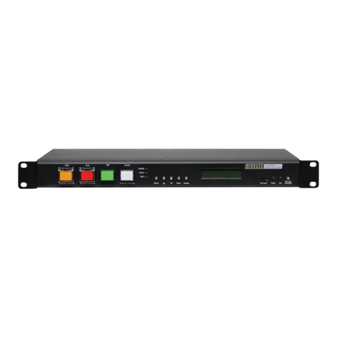
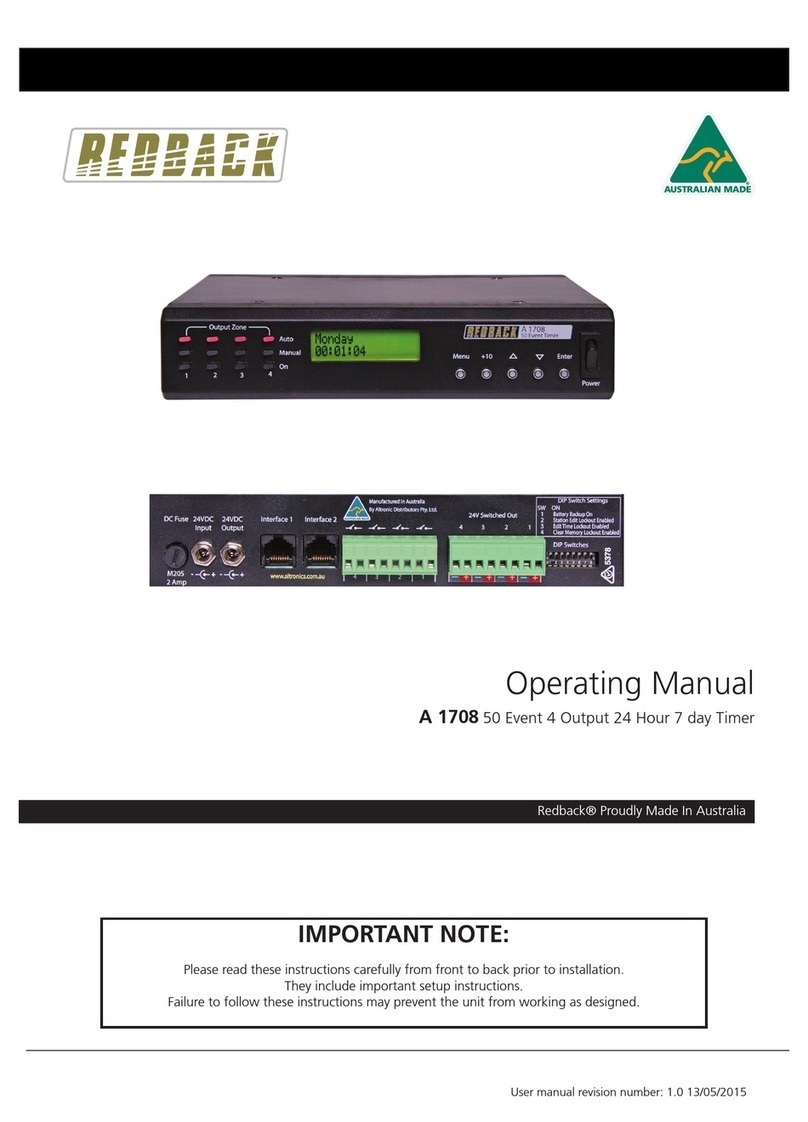
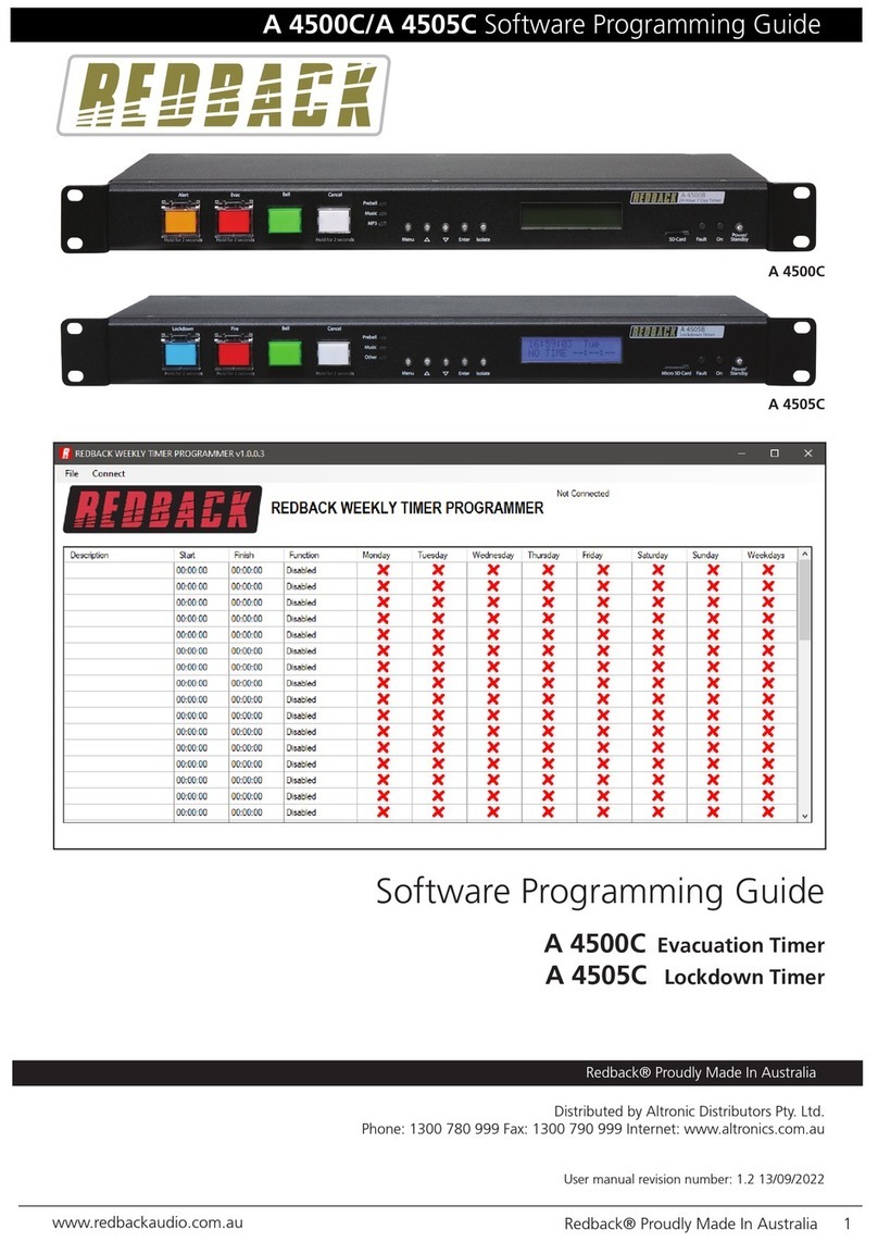
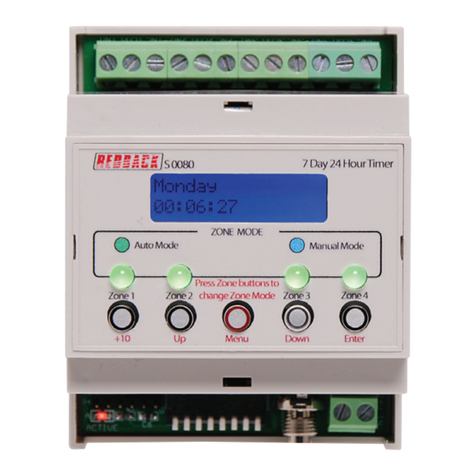
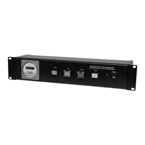
Redback A 2064 User manual

www.redbackaudio.com.au Redback® Proudly Made In Australia 1
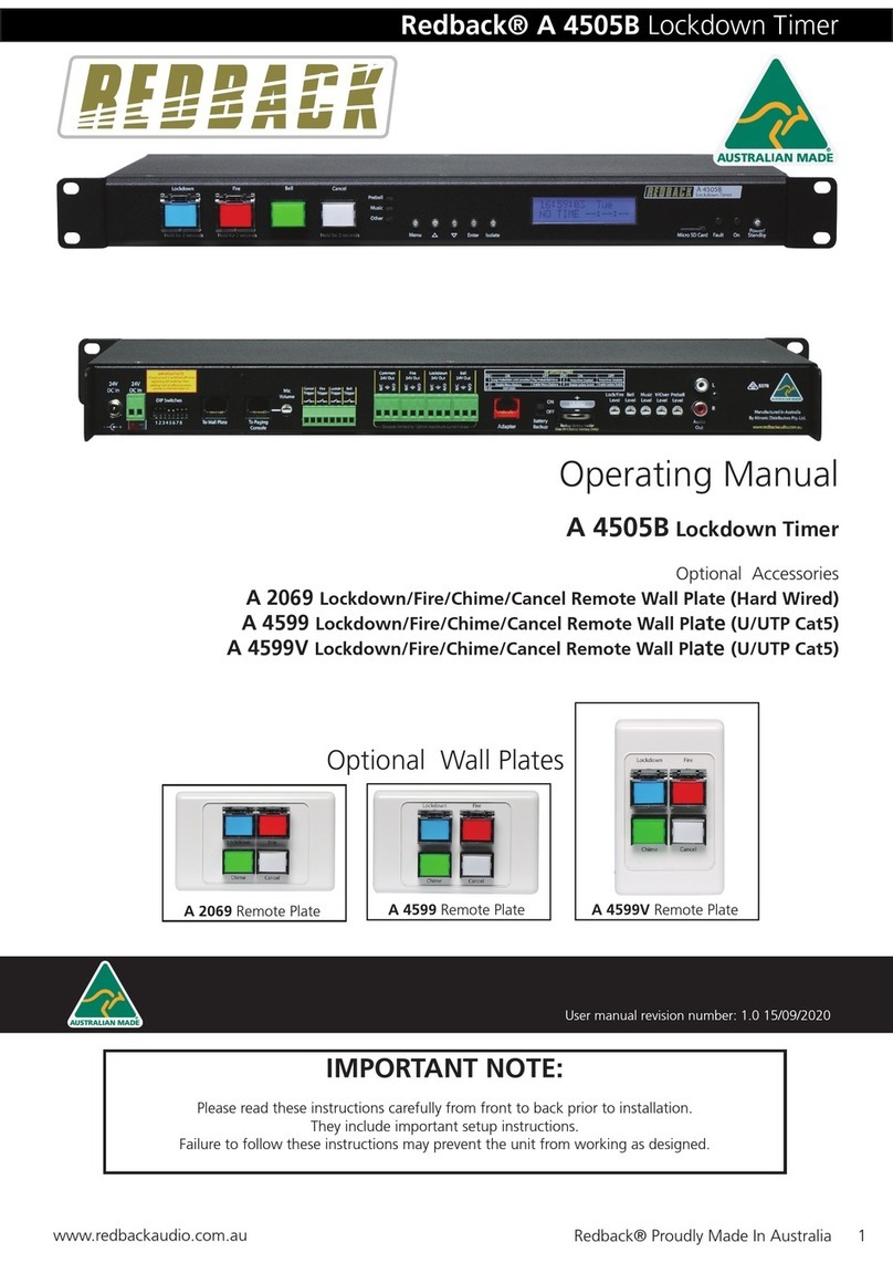
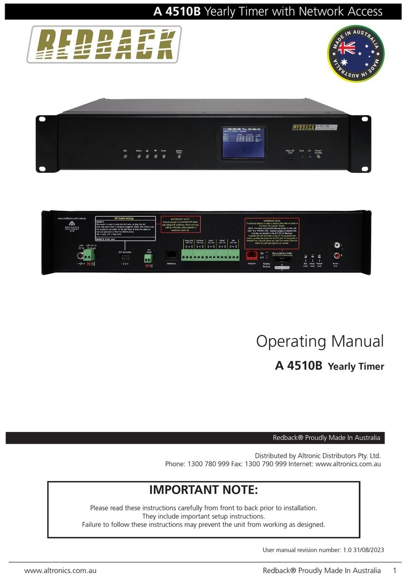
Redback® A 4505B Lockdown Timer
Operating Manual
A 4505B Lockdown Timer
Optional Accessories
A 2064 Lockdown/Fire/Cancel Remote Wall Plate (Hard Wired)
A 2069 Lockdown/Fire/Bell/Cancel Remote Wall Plate (Hard Wired)
A 4599 Lockdown/Fire/Bell/Cancel Remote Wall Plate (U/UTP Cat5)
A 4599V Lockdown/Fire/Bell/Cancel Remote Wall Plate (U/UTP Cat5)
IMPORTANT NOTE:
Please read these instructions carefully from front to back prior to installation.
They include important setup instructions.
Failure to follow these instructions may prevent the unit from working as designed.
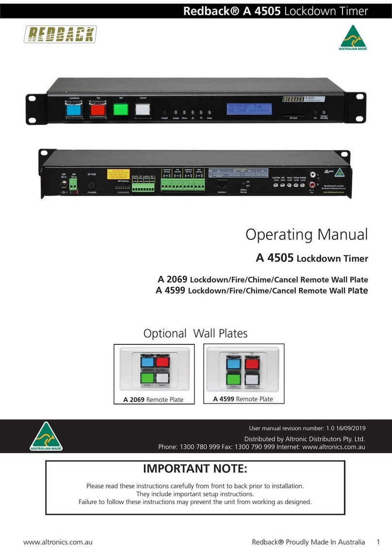
Optional Wall Plates
A 4599 Remote Plate
A 2069 Remote Plate
Distributed by Altronic Distributors Pty. Ltd.
Phone: 1300 780 999 Fax: 1300 790 999 Internet: www.altronics.com.au
User manual revision number: 1.1 12/08/2021
A 4599V Remote Plate
A 2064 Remote Plate

www.redbackaudio.com.au
Redback® Proudly Made In Australia2
Redback® A 4505B Lockdown Timer
REDBACK is a registered trademark of Altronic Distributors Pty Ltd
Since 1976 Redback ampliers have been manufactured in Perth, Western Australia by Altronics. With over 40 years
experience in the commercial audio industry, we offer consultants, installers and end users reliable products of high build
quality with local product support. We believe there is signicant added value for customers when purchasing an
Australian made Redback amplier or PA product
Australian Made Status
All Redback house products made by Altronics will now be sporting the ofcial Australian Made logo. Since starting
manufacturing of commercial audio equipment in the mid 70’s we have always taken pride in producing a quality local
product.
The new adoption of the Australian Made logo will help us get the word out to local and export markets that our
products carry the ofcial compliance seal of the Australian Made campaign. We have always pushed our ‘local is better’
line in all of our marketing efforts, it’s always an added boost when you are backed up by a widely recognised and
respected icon.
Industry leading 10 year warranty.
There’s a reason we have the industry leading DECADE warranty. It’s because of a long tried and tested history of
bulletproof reliability. We’ve heard PA contractors tell us they still see the original Redford amplier still in service in
schools - that’s over 40 years of operation - and still going strong!
Published by Altronic Distributors
© 2021 Altronic Distributors

www.redbackaudio.com.au Redback® Proudly Made In Australia 3
Redback® A 4505B Lockdown Timer
CONTENTS
1.0 Overview Page
1.1 Introduction 4
1.2 Features 4
1.3 What’s in the box 4
1.4 Front panel guide 5
1.5 Rear panel connections 6
2.0 Setup
2.1 Initial Setup 8
2.2 Lockdown, Fire and Bell Switches 9
2.3 Programming the timing events using the front buttons 10
2.4 Programming the timing events using the supplied PC software 12
2.5 Setting the current time 16
2.6 Deleting a programmed time 17
2.7 Reseting all programmed times 17
2.8 Audio Connections 18
2.9 Voice-Over Messages 18
2.10 DIP Switch settings 18
2.11 24V DC Output Connections 19
3.0 Remote Wall Plates
3.1 A 2064 and A 2069 Remote Plates 19
3.2 A 4599 and A 4599V Remote Plate 21
4.0 Troubleshooting
4.1 Symptoms and Remedies 22
4.2 RJ45 Cabling Conguration 23
5.0 Firmware Update 23
6.0 Specications & Warranty 24

www.redbackaudio.com.au
Redback® Proudly Made In Australia4
Redback® A 4505B Lockdown Timer
1.0 OVERVIEW
1.1 INTRODUCTION
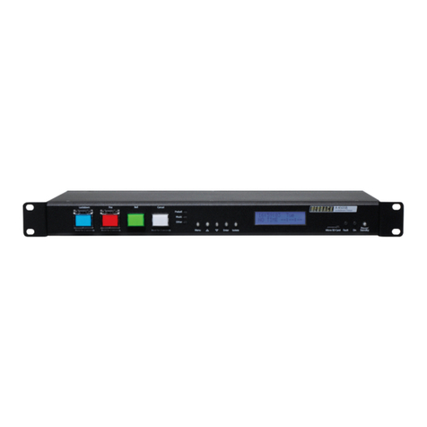
The Redback®A 4505B is a weekly timer and Lockdown and Fire Alarm controller all housed in a convenient 1RU rack
mount chassis. A total of 50 “event” switching times are available through the timing functions. Each event can be set to
turn on any single day of the week or on multiple days, from 1 sec up to 24 hours. When a timing event is activated, an MP3
audio le will be played and output through the dual RCA line level output.
There are fourteen MP3 playback options for the timing events, which include the Bell, Prebell, Music and folders 5-15. A
Micro SD card which is supplied, houses all the MP3 les to be played as well as storing all the timing events (Note: The audio
les must be in MP3 format). The timing events can be programmed via the unit’s front buttons which is a bit cumbersome,
or they can be programmed with the supplied PC software (also available as a download from www.altronics.com.au).
The timing events can also be programmed to only trigger the Bell 24V out (and in turn the common 24V Out), with no
audio output. This is activated by setting the output to the “relay” option in the programming setup.
The Lockdown/Fire controller is designed around industry standard building emergency Lockdown/Fire requirements. When
connected to a paging system amplier, building occupants can be alerted and/or evacuated in the event of an emergency
e.g. re, gas leak, bomb scare, earthquake. Lockdown & Fire switches on the front of the unit are tted with safety covers
to prevent accidental operation.
The Lockdown, Fire and Bell tones and the cancel function are triggered by the front switches, or by the rear terminal con-
tacts for remote activation. Switched 24V DC Out connections are provided for Bell, Lockdown, Fire or a Common out. These
contacts are for connection of override relays in remote volume controls, warning strobes, bells etc.
The Lockdown and Fire tones are stored on a Micro SD card (Emergency Tones which conform to AS1670.4 are supplied) to
allow the user to provide any tones they require (Note: The audio les must be in MP3 format).
The Fire mode has a voice over option for the playback of a Fire message after every playback of the Fire tone. The voice over
message is also stored on the SD card and is DIP switch enabled.
The Lockdown mode has a voice over option for the playback of a Lockdown message after every playback of the Lockdown
tone. The voice over message is also stored on the SD card and is DIP switch enabled.
1.2 FEATURES
• MP3 audio format for Bell, Prebell and Music timing outputs
• MP3 audio format Emergency Tones conform to AS 1670.4 (supplied)
• Random play of MP3 les for Prebell and Music triggers
• Easy PC based timing event setup
• Local push button operation of Lockdown, Fire and Bell
• Remote triggering of Lockdown, Fire and Bell
• MP3 audio format Voice over message (Available in the Lockdown and the Fire cycle)
• Switched 24VDC output for Bell, Lockdown or Fire mode
• Pluggable screw terminal connections
• Auxiliary level output
• Battery backup of current time
• 24V DC operation
• Standard 1U 19” rack mount case
• Suitable for any amplier with an auxiliary input
• 10 Year Warranty
• Australian Designed and Manufactured
1.3 WHAT’S IN THE BOX
Redback®A 4505B Lockdown Timer
24V 2A DC Plugpack
Instruction Booklet

www.redbackaudio.com.au Redback® Proudly Made In Australia 5
Redback® A 4505B Lockdown Timer
1.4 FRONT PANEL GUIDE
Fig 1.4A shows the layout of the A 4505B front panel.
Fig 1.4A
1 Lockdown Tone Activation Switch
This switch is used to activate the Lockdown tone. It may need to be pressed for up to 2 seconds to activate.
2 Fire Tone Activation Switch
This switch is used to activate the Fire tone. It may need to be pressed for up to 2 seconds to activate.
3 Bell Tone Activation Switch
This switch is used to activate the Bell tone.
4 Cancel Tone Activation Switch
This switch is used to cancel the Lockdown, Fire or bell tone. It may need to be pressed for up to 2 seconds to
activate.
5 Status LEDS
Prebell LED - This LED indicates when the Prebell is active.
Music LED - This LED indicates when an MP3 from the Music Folder is active.
Other LED - This LED indicates when an MP3 from one of the Music Folders 5 - 15 is active.
6 Menu and Navigation Switches
These switches are used to navigate the menu functions of the unit.
7 Isolate Switch
This switch is used to isolate the timing functions of the unit. Note: When this is enabled the Alert, Evac and
Chime buttons and remote triggers will still function.
8 LCD Display
This displays the current time and other timing functions.
9 Micro SD Card
This is used to store the MP3 audio les for the Prebell, Bell, Alert, Evac, Music and MP3 folders 5-15 playback. It
also stores the timing events for the timer. (More details in section 2.1).
NOTE: All folders except the “Prebell” and “Music” folders must have only one MP3 le installed. The “Prebell”
and “Music“ folders can have unlimited MP3 les (depending on available storage) and will then randomly play
the MP3 les in the folder each time the corresponding prebell or music contact is triggered.
Note : MP3 les should have the following specications for optimum performance.
128kbps, 44.1kHz, 32bit, VBR or CBR, Stereo (even better as mono).
10 Fault Indicator
This LED indicates that the unit has a fault.
11 On Indicator
This LED indicates the unit is ON.
12 Standby Switch
When the unit is in standby mode this switch will illuminate. Press this button to switch the unit ON. Once the
unit is ON the On indicator will illuminate. Press this switch again to put the unit back in standby mode.
24 Hour 7 Day Timer
A 4500
Lockdown Timer
A 4505B
1 2 3 4 5 7
689 10 11
FireLockdown Bell Cancel
Isolate
Menu Enter
Hold for 2 seconds Hold for 2 seconds Hold for 2 seconds
Prebell
Music
Other
12
On Standby
Micro SD Card Power/
Fault

www.redbackaudio.com.au
Redback® Proudly Made In Australia6
Redback® A 4505B Lockdown Timer
1.5 REAR PANEL CONNECTIONS
Fig 1.5A shows the layout of the A 4505B rear panel.
Fig 1.5A
1 Common 24V Out
This is a common 24V DC output which is activated when any of the Prebell, Bell, Music, Lockdown or Fire tones
are activated. The terminals provided can be used for “Normal” or “Failsafe” modes (see section 2.10 for more
details).
2 Fire 24V Out
This is a 24V DC output which is activated when the Fire tone is activated. The terminals provided can be used
for “Normal” or “Failsafe” modes (see section 2.10 for more details).
3 Lockdown 24V Out
This is a 24V DC output which is activated when the Lockdown tone is activated. The terminals provided can be
used for “Normal” or “Failsafe” modes (see section 2.10 for more details).
4 Bell 24V Out
This is a 24V DC output which is activated when the Bell tone or relay only (No MP3 option) is activated. The
terminals provided can be used for “Normal” or “Failsafe” modes (see section 2.10 for more details).
5 RJ45 Adapter
This RJ45 port is for future connection of Redback devices.
6 Backup Battery Switch
Use this switch to activate the backup battery. (Note: The backup battery only backs up the current time).
7 Backup Battery
Replace this battery with a 3V CR2032 only. Remove by pulling the battery.
Note: The positive side of the battery faces upward.
8 Lockdown/Fire Volume
Adjust this trimpot to adjust the Alert and Evacuation tones playback volume.
9 Bell Volume
Adjust this trimpot to adjust the Bell playback volume.
10 Music Volume
Adjust this trimpot to adjust the Music playback volume.
11 Voice-over Volume
Adjust this trimpot to adjust the message voice-over playback volume.
12 PreBell Volume
Adjust this trimpot to adjust the PreBell playback volume.
1 2 3 4 5 8 9 10 11 12 13
14
21 19
22
23 15
16
17
Mic
Volume
To Paging
Console
To Wall Plate Adapter
CR2032
Backup Battery Holder
(Use 3V CR2032 Battery Only)
Manufactured in Australia
By Altronic Distributors Pty. Ltd.
N/C
N/O
L
R
Audio
Out
Prebell
Level
V/Over
Level
DIP Switches
Common
24V Out
IMPORTANT NOTE
Ensure power is switched off when
adjusting DIP switches. New
settings will be effective when
power is switched back on.
N/C
N/O
Fire
24V Out
N/C
N/O
Lockdown
24V Out
N/C
N/O
Bell
24V Out
+
-
24V
DC In
+_
24V
DC In
Music
Level
Bell
Level
Lock/Fire
Level
1 2 3 4 5 6 7 8
Battery
Backup
Cancel
Trigger
Fire
Trigger
Lockdown
Trigger
Bell
Trigger
ON
OFF
www.redbackaudio.com.au
1 2 3 4 5 6 7 8
Outputs limited to 120mA maximum current draw
6 7
20 18

www.redbackaudio.com.au Redback® Proudly Made In Australia 7
Redback® A 4505B Lockdown Timer
13 Audio Out RCA Connectors
Connect these outputs to the input of the background music amplier.
14 Bell Contact
These contacts are for remote triggering of the Bell tone. These could be triggered by a remote switch or other
closing contact.
15 Lockdown Contact
These contacts are for remote triggering of the Lockdown tone. These could be triggered by a remote switch or
other closing contact.
16 Fire Contact
These contacts are for remote triggering of the Fire tone. These could be triggered by a remote switch or
other closing contact.
17 Cancel Contact
These contacts are for remote triggering of the cancel function. These could be triggered by a remote switch or
other closing contact.
18 Mic Volume
Adjust this trimpot to adjust the Paging Microphone volume (Microphone currently not available).
19 RJ45 interface
This RJ45 port is for connection of a microphone paging console (currently not available).
20 RJ45 interface
This RJ45 port is for connection to the A 4599 or A 4599V wall plates.
21 Dip Switches
These are used to select various options. Refer to DIP Switch Settings section.
22 24V DC Input (Backup)
Connects to a 24V DC backup supply with at least 1 amp current capacity. (Please observe the polarity)
23 24V DC input
Connects to a 24V DC Plugpack with 2.1mm Jack.

www.redbackaudio.com.au
Redback® Proudly Made In Australia8
Redback® A 4505B Lockdown Timer
2.0 SETUP GUIDE
2.1 INITIAL SETUP
For the unit to function correctly, the supplied SD card must be installed and have MP3 les in each of the Lockdown, Fire,
Bell, Prebell and Music folders as shown in Fig 2.1.
NOTE: The unit will display an MP3 error message on the screen if any of these folders on the SD card are left empty. I.e. the
Lockdown, Bell, Fire, Music and Prebell folders must all have an MP3 le inside.
The Micro SD card should have the following folders already installed “Lockdown, Bell, Fire, Music, Prebell, Voice and 5-15”.
If these folders don’t exist they will have to be created.
Inside each of these folders (except the 5-15 folders) there will be a sample MP3 audio le. A library of sample MP3 les is
supplied (in the #LIBRARY# folder).
NOTE: All folders except the “Prebell” and “Music” folders must have only one MP3 le installed. The “Prebell” and “Music“
folders can have unlimited MP3 les (depending on available storage) and will then randomly play the MP3 les in the folder
each time the corresponding prebell or music contact is triggered or time activated.
In order to install MP3 les onto the Micro SD card, or move the sample MP3’s to their relevant folders, the Micro SD card
will need to be connected to a PC. You will need a PC or laptop equipped with a Micro SD card reader to do this. If a Micro
SD slot is not available then the Altronics D 0371B USB Memory Card Reader or similar would be suitable (not supplied).
You will rst need to remove power from the A 4505B and then remove the Micro SD card from the front of the unit.
To remove the Micro SD card push the card in and it will eject itself.
Step by step guide to install an MP3 into it’s associated folder with a Windows based PC.
Step 1: Make sure the PC is on and card reader connected and correctly installed. Then insert the Micro SD card into the
reader.
Step 2: Go to “My Computer” or “This PC”and open the Micro SD card which is usually marked “Removable disk”.
In this case it is named “Removable disk (O:)”. Select the removable disk and then you should get a window that looks like
gure 2.1.
Fig 2.1

www.redbackaudio.com.au Redback® Proudly Made In Australia 9
Redback® A 4505B Lockdown Timer
Step 3: Open the folder to change, in our example the “bell” folder, and you should get a window that looks like gure 2.2.
Fig 2.2
Step 4: You should see an MP3 le “Schoolbell.mp3”.
This MP3 le needs to be deleted and replaced by the MP3 le you want to play when you activate the bell. The MP3 le
name is not important only that there is one MP3 le in the “bell” folder. Make sure you delete the old MP3!
Note 1: MP3 les should have the following specications for optimum performance.
128kbps, 44.1kHz, 32bit, VBR or CBR, Stereo (even better as mono).
Note 2: All folders except the “Prebell” and “Music” folders must have only one MP3 le installed. The “Prebell” and “Music”
folders can have unlimited MP3 les (depending on available storage).
Note that the new MP3 le cannot be “Read only”. To check this right
click on the MP3 le and scroll down and select Properties, you will get a
window that looks like gure 2.3. Make sure the “Read Only” box has no
tick in it.
Fig 2.3
Repeat these steps for the other folders.
The new MP3’s are now installed on the SD card, and the card can be removed from the PC following windows safe card
removal procedures. Make sure the A 4505B is OFF and insert the SD card into the SD card slot ; it will click when fully in-
serted. The A 4505B can now be switched back On. If all the MP3 les are OK then the unit will display the time screen. If
an MP3 error message is is displayed, there is a problem with one or more of the MP3 les.

www.redbackaudio.com.au
Redback® Proudly Made In Australia10
Redback® A 4505B Lockdown Timer
2.2 LOCKDOWN, FIRE AND BELL SWITCHES
The Lockdown, Fire and Bell switches on the front of the unit all work in momentary mode. ie. The Lockdown tone will
continue to sound after the Lockdown switch is momentarily pressed and the Fire tone will continue to sound after the Fire
switch is momentarily pressed. There is an automatic Lockdown to Fire switch-over option associated with the front panel
switches (refer to section 2.8).
Note 1: The tone that is being sounded (ie Lockdown, Fire, bell) will be indicated by the illumination of the relevant front
panel indicator.
Note 2: To cancel a tone either use the remote cancel contacts or the front cancel button. Note the cancel button will need
to be depressed for 2 seconds. This is to prevent accidental cancelling of a tone.
The Lockdown, Fire and Bell tones are stored on the supplied SD card. Separate folders are supplied on the SD card for each
tone. It is up to the user to provide the MP3 les (they must be in MP3 format) for each of the tones. A library of sample
MP3 les is supplied (in the #LIBRARY# folder). See section 2.1 for more details.
NOTE: The unit will display an MP3 error message on the screen if any of the folders on the SD card are left empty. I.e. the
Lockdown, Bell, Fire, Music, Prebell and Voice folders must all have an MP3 le inside.
Once these Lockdown, Fire and Bell outputs are activated, the corresponding 24V switched outputs will become active (refer
to section 2.6 for more details)
2.3 PROGRAMMING THE TIMING EVENTS USING THE FRONT BUTTONS
If the unit starts up correctly and no error messages are displayed, the model number will be displayed briey before the
current time is shown. See Fig 2.4.
If this screen doesn’t appear and instead an MP3 error message is displayed, then either the SD card is not inserted correctly
or there is a missing MP3 le.
NOTE: The unit will display an MP3 error message on the screen if any of the folders on the SD card are left empty. I.e. the
Lockdown, Bell, Fire, Music, Prebell and Voice folders must all have an MP3 le inside.
The main screen (Current Time Screen) shown in Fig 2.5 displays the current time and day, and the next programmed event.
When this screen is displayed the unit is running in “AUTO MODE” and therefore all outputs will work as programmed.
However if the unit is in any of the sub menu’s (Menu Mode) the unit will no longer respond to any event that has been
programmed to occur. On exiting the menu, the timer will check all programmed events and update the status of the output
zones.
In order to set up the timer, the station (or event) times will need to be programmed. This can be achevied by using the but-
tons on the front of the unit or via the PC software (supplied on the SD card) see section 2.4 for more details.
PROGRAMMING THE TIMING EVENTS USING THE FRONT BUTTONS
There are ve buttons on the front of the timer which are used to program the unit and navigate the various menus.
Press the “Menu” button on the front of the timer. The unit is now in “Menu Mode” and the screen should display the
“Times Adjust” Screen. This is the rst of 5 sub menu screens which are navigated by pressing the up and down buttons
as shown in Fig 2.6. Pressing the Menu button again will exit the menu structure and return the user to the Main Screen.
SPECIAL NOTE ABOUT “AUTO MODE” OPERATION
If the timer is not displaying the main clock screen, where the time is changing, the unit is not running in
“Auto Mode”. This means it will not be checking any of the programmed events and hence will not activate
any outputs automatically.
Essentially this means that as soon as the Menu button is pressed the unit is no longer in “Auto Mode”.
Make sure to return to the main screen by exiting all menu’s when not making changes.
Altronics A 4505
EVACUATION TIMER
Fig 2.4
Fig 2.5
00:00:00 Mon
NO TIME --:--:--
www.redbackaudio.com.au Redback® Proudly Made In Australia 11
Redback® A 4505B Lockdown Timer
Select the desired sub menu by pressing the
“Enter” button.
There are 4 options to choose from.
1) Times Ajdust
2) Clock Adjust
3) Delete Times
4) Reset All Times
5) EV Changeover
2.3.1 Times Adjust
After selecting this option, the screen as shown in Fig 2.7 should appear.
This option allows the user to enter the Station (Event) information which includes the event “Turn on time”, “Period” and
“Output MP3”.
The top left text is the time event number. Up to 50 events can be programmed into the A 4505B. Pressing the “up” and
“down” buttons at this stage will move up and down through the events 1- 50. The top right text indicates that TIME1
(Event1) is currently disabled. The bottom left text refers to the time this event will happen (i.e. the “Start” Time).
Press the “Enter” button to edit this event, or press the “Menu” button to exit.
Pressing the Enter button will take you to the “Editing Time” screen (Refer to g 2.8). This is where the event “Start” time
is entered. The cursor will be positioned over the hour section of the time. Use the up and down buttons to change the
hour and then press the “Enter Button” to conrm the hour. The cursor will move to the minutes section of the time. Use
the up and down buttons to change the minutes and then repeat the process again for the seconds. Once the seconds have
been updated the screen will change to the “Period” set screen (Refer to g 2.9) . This is where the length of time the event
should occur, is recorded.
Fig 2.7
MENU
1)TIMES ADJUST
MENU
2) CLOCK ADJUST
MENU
3)DELETE TIMES
MENU
5)EV CHANGEOVER
00:00:00 Mon
NO TIME__00:00:00
Menu
Main Screen
Press the UP and DOWN
buttons to scroll up and
down.
Enter Press the ENTER
button to make your
selection
Menu Press the MENU
button to exit at any
time.
MENU
4)RESET ALL TIMES
Fig 2.6
TIME1 DISABLED
00:00:00 EDIT?
Fig 2.8
EDITING TIME1
START 00:00:00

www.redbackaudio.com.au
Redback® Proudly Made In Australia12
Redback® A 4505B Lockdown Timer
Once again, use the up and down buttons to set the hour, minutes and seconds and press enter when nished. Once the
period has been set, the desired output MP3 for this event is to be set using the MP3 output screen (See g 2.10).
The MP3 output defaults to Prebell. Scroll through the other options by using the up and down buttons. The MP3 output
can be set to Prebell, Bell, Music, No MP3 or the output can be disabled. These MP3 outputs correspond to the MP3 audio
les located in the Prebell, Bell and Music folders on the SD card.
RELAY OUTPUT CONFIGURATION
The 24V switched outputs associated with the Prebell, Bell and Music folders are as follows.
When the Bell output is active the Bell 24V output and Common 24V output will become active.
When the Prebell and Music outputs are active the the Common 24V output only will become active.
The NO MP3 option will activate the Bell and Common 24V output, but no audio le will be played.
Once the desired output for the event has been set, press the enter button to move to the next screen (See g 2.11). This
is where the days of the week this event will occur are entered. The top right line of text refers to the days of the week,
Monday through to Sunday. The line of text below this sets each day “ON” or “OFF”. Use the up and down buttons to set
the day to Y for “ON” and N for “OFF”.
Once the days of the week are set, press the enter button to conrm and be returned to the main menu. Repeat this process
for any other events to be programmed.
This process of entering the events can be quite time consuming. An easier method of entering this information is by using
the supplied PC software which is provided on the SD card (see section 2.4).
2.4 PROGRAMMING THE TIMING EVENTS USING THE SUPPLIED PC SOFTWARE
The PC software is provided on the units’ SD Card and is called “RedbackA4500TimerProgrammer” or similar.
This software can be used to program the Redback®A 4500B or Redback®A 4505B.
Note: Updated versions are available for download from www.altronics.com.au or redbackaudio.com.au.
In order to access the program, the SD card will need to be connected to a PC. You will need a PC or laptop equipped with
an SD card reader to do this. If an SD slot is not available then the Altronics D 0371A USB Memory Card Reader or similar
would be suitable (not supplied).
You will rst need to remove power from the A 4505B and then remove the SD card from the rear of the unit.
To remove the SD card push the card in and it will eject itself.
Make sure the PC is on and card reader connected and correctly installed. Then insert the SD card into the reader.
Fig 2.9
EDITING TIME1
PERIOD 00:00:00
Fig 2.10
EDITING TIME1
MP3---- PREBELL
Fig 2.11
DAYS- MTWTFSS
NNNNNNN

www.redbackaudio.com.au Redback® Proudly Made In Australia 13
Redback® A 4505B Lockdown Timer
Go to “My Computer” or “This PC” and open the SD
card which is usually marked “Removable disk”.
In this case it is named “Removable disk (M:)”. Select the
removable disk and then you should get a window that
looks like gure 2.12.
The program can be run on the SD card or it could be copied to the PC desktop or another folder and run from there. Double
click on the .exe le - RedbackA4500TimerProgrammer or similar. The programming screen should appear as shown in g
2.13.
If the program doesn’t run then the .NET Framework might need to be updated on your PC.
This must be updated to the .NET Framework 4, available on the microsoft website.
Fig 2.13
All 50 events can be accessed on the screen by scrolling up and down. If you previously saved some timing information
using the buttons on the A 4505B then these times should be displayed. Otherwise the timing information should all be
blank as shown. The information is saved in a le labelled “cong.cnf”. This le should already be supplied on the SD card
and should be blank as shown.
Entering the timing events is very straight forward.
Double click on any line and a new window should pop up as shown in g 2.14, which has the event details outlined.
Fig 2.12

www.redbackaudio.com.au
Redback® Proudly Made In Australia14
Redback® A 4505B Lockdown Timer
Fig 2.14
An event can now be programmed from this window. A description of the event can be added if desired (such as Pre bell,
Morning Tea, Lunch etc), and the start and nish times can all be entered. Selecting the days of the week is as simple as
clicking the desired days or selecting the weekdays box, if all weekdays are required.
EVENT OUTPUT
The Event output is selected by the Output dropdown box.
There are fourteen MP3 playback options (Bell, Pre-Bell, Music and 5-15) and a relay only option for
the output of the event. The MP3 options relate directly to the folders on the SD card. The Pre-Bell and
Music folders can have multiple MP3 les providing random play options. The Bell folder and folders
5-15 must have only one MP3 le each.
Figure 2.15 shown below illustrates an example. This event is the prebell for a primary school and is
programmed to activate 5 minutes before the rst bell of the day. The MP3 le located in the Prebell
folder on the SD card will be played at 8:55:00 and continue to play until 08:59:59.
Once the event programming has been nalised, press the OK button.
Fig 2.15

www.redbackaudio.com.au Redback® Proudly Made In Australia 15
Redback® A 4505B Lockdown Timer
The event should now appear in the programming window as shown in g 2.16.
Fig 2.16
Another event is now added by following the same steps. Double click on a blank line and then enter the details required as
illustrated in g 2.17. This is the rst bell of the day for the primary school, the A 4505B is being installed at.
Fig 2.17
Press the OK button and the second event now appears in the programming screen as shown in g 2.18.

www.redbackaudio.com.au
Redback® Proudly Made In Australia16
Redback® A 4505B Lockdown Timer
Fig 2.18
As the events are added they will be listed in chronological order. (I.e. In time order). If a new event was programmed, to
start at 08:45:00 for instance, this new event would appear before the prebell event.
Continue to enter the events in this manner and then save the program by clicking le and then save as. The le must be
saved as cong.cnf on the SD card in place of the le already on the SD card.
With the events now programmed on the SD card, the card can be removed from the PC following windows safe card
removal procedures. Make sure the A 4505B is OFF and insert the SD card into the slot in the rear; it will click when fully
inserted.
The A 4505B can now be switched back On. If all is well, after the startup screen is displayed the current time and next event
should be displayed on the screen.
2.5 SETTING THE CURRENT TIME
Press the “Menu” button on the front of the timer. The unit is
now in “Menu Mode” and the screen should display the “Times
Adjust” Screen. This is the rst of 5 sub menu screens which
are navigated by pressing the up and down buttons as shown
in Fig 2.19. Pressing the Menu button again will exit the menu
structure and return the user to the Main Screen.
Select the CLOCK ADJUST sub menu.
After selecting this option, the screen as shown in Fig 2.20
should appear.
MENU
1)TIMES ADJUST
MENU
2) CLOCK ADJUST
MENU
3)DELETE TIMES
MENU
5)EV CHANGEOVER
00:00:00 Mon
NO TIME__00:00:00
Menu
Main Screen
Press the UP and DOWN
buttons to scroll up and
down.
Enter Press the ENTER
button to make your
selection
Menu Press the MENU
button to exit at any
time.
MENU
4)RESET ALL TIMES
Fig 2.19

www.redbackaudio.com.au Redback® Proudly Made In Australia 17
Redback® A 4505B Lockdown Timer
The cursor will be positioned over the hour section of the time. Use the up and down buttons to change the hour and then
press the “Enter Button” to conrm the hour. The cursor will move to the minutes section of the time. Use the up and down
buttons to change the minutes and then repeat the process again for the seconds. Once the seconds have been updated
the cursor will move to the day of the week. Use the up and down buttons again to change the day and then press enter
to conrm. The time is now set.
2.6 DELETING A PROGRAMMED TIME
Press the “Menu” button on the front of the timer. The unit is now in “Menu Mode” and the screen should display the
“Times Adjust” Screen. This is the rst of 5 sub menu screens which are navigated by pressing the up and down buttons
as shown in Fig 2.19. Pressing the Menu button again will exit the menu structure and return the user to the Main Screen.
Select the DELETE TIMES sub menu.
After selecting this option, the screen as shown in Fig 2.22 should appear.
From this point the “Up” and “Down” buttons can be used to scroll through the different times, or press the “Enter” but-
ton to delete this time. After deleting the time, a message will indicate that the time has been cleared and the next time
will then be displayed on the screen. Press “Enter” to delete, “Menu” to exit or the “Up” and “Down” buttons to scroll to
another time.
A time can also be deleted using the PC software.
See section 2.4 for instructions regarding accessing the event programming. A time can be removed by double clicking on
the required programmed line and then pressing the “CLEAR” button.
2.7 RESET ALL PROGRAMMED TIMES
Press the “Menu” button on the front of the timer. The unit is now in “Menu Mode” and the screen should display the
“Times Adjust” Screen. This is the rst of 5 sub menu screens which are navigated by pressing the up and down buttons
as shown in Fig 2.19. Pressing the Menu button again will exit the menu structure and return the user to the Main Screen.
Select the RESET ALL TIMES sub menu.
After selecting this option, the screen as shown in Fig 2.23 should appear.
Press the “UP” button to reset all the times programmed and stored on the SD card. Press the “No” button to exit without
resetting the times.
Fig 2.20
EDITING CLOCK
00:00:00 Mon
Fig 2.22
TIME1 PREBELL
07:55:00 DELETE?
Fig 2.23
RESET ALL TIMES
UP=YES / DN = NO

www.redbackaudio.com.au
Redback® Proudly Made In Australia18
Redback® A 4505B Lockdown Timer
2.8 AUDIO CONNECTIONS
Audio Output:
This output consists of stereo RCA sockets with an output of 0dBm into a 600Ω input. This is suitable for most PA
amplier auxiliary inputs.
Rear Panel Volume Controls:
The output levels of the Lockdown/Fire, Prebell, Bell, Music and Voice Over tones can all be adjusted via trimpots located on
the rear of the unit.
2.9 VOICE-OVER MESSAGES
The Redback®A 4505B has options for an MP3 message to be played during the Lockdown and the Fire modes.
The voice-over messages are output after every playback of the corresponding Lockdown or Fire MP3 tone.
i.e. if the Lockdown mode is activated the Lockdown MP3 will play once, then the Lockdown voice-over message will play
once and this will repeat until cancelled.
The voice-over messages can be enabled by DIP switch 2 (See DIP Switch Settings).
Note: This option will enable both voice-over messages. If only one of the two messages is required, leave the non required
voice-over folder empty.
e.g. if the Fire voice over message is required ,but the Lockdown voice-over message is not, make sure the folder located in
Removable Disk( ):\voice\lockdown is empty.
2.10 DIP SWITCH SETTINGS
The A 4505B has various options which are set by the DIP switches on the rear of the unit. These are outlined below and in
gure 2.24.
Switch 1
This switch is used to either loop the Bell/Prebell, or play the Bell/Prebell only once after it has been triggered.
ON = Loop, OFF = Play Once
Switch 2
DIP switch 2 enables or disables the voice over message. The voice-over message is played in between every three cycles of
the Fire tone.
ON = Enabled, OFF = Disabled
Switch 3
This switch can be used to lockout the menu button, to deter tampering with the programmed times.
ON = Menu button disabled, OFF = Menu button enabled
Switch 4
This switch can be used to lockout the front isolate button.
ON = Isolate button disabled, OFF = Isolate button enabled
Switch 5-8 Not Used
Fig 2.24
ON OFF
1
3Disable Menu Options
SW
DIP SWITCH SETTINGS
5-8 NOT USED
Enable Menu Options
Loop PreBell/Bell Until Cancelled Play Prebell/Bell Once
ON OFF
2Voice Over Enabled
SW
Voice Over Disabled
4Disable Isolate Switch Enable Isolate Switch
IMPORTANT NOTE:
Ensure power is switched off when adjusting DIP switches.
New settings will be effective when power is switched back on.

www.redbackaudio.com.au Redback® Proudly Made In Australia 19
Redback® A 4505B Lockdown Timer
2.11 24V OUTPUT CONNECTIONS
These contacts can be used for connection of override relays in remote volume controls, or strobes for unusually noisy en-
vironments. An override relay is necessary where attenuators are used so that the Lockdown tone, Fire tone or message is
broadcast at full volume regardless of the volume setting on the individual volume control (attenuator).
Lockdown/Fire 24V Out:
These contacts are for switched 24V outputs whenever the Lockdown or Fire tones are activated. These may be used to run
external systems such as strobes in unusually noisy environments, or override relays in remote volume controls.
When this output becomes active, 24V will appear between the N/O contact and the GND contact. When this output is not
active 24V will appear between the N/C contact and the GND.
Bell 24V Out:
These contacts are for switched 24V outputs whenever the Bell or Relay Only (No MP3 option) are activated These contacts
are for operating an external relay used to operate something like a lunch bell etc.
When this output becomes active, 24V will appear between the N/O contact and the GND contact. When this output is not
active 24V will appear between the N/C contact and the GND.
Common 24V Out:
These contacts are for switched 24V outputs whenever the Lockdown, Fire, Bell, Prebell or Relay Only (No MP3 option) tones
are activated. When this output becomes active, 24V will appear between the N/O contact and the GND contact. When this
output is not active 24V will appear between the N/C contact and the GND.
3.0 REMOTE WALL PLATES
There are a number of wall plates which can be connected to the A 4505B for remote triggering of the Lockdown, Fire
and Bell tones and for remotely cancelling any tones which may be active.
3.1 A 2064 and A 2069 Remote Plates
A 2064 A 2069
The Redback®A 2064 wall plate provides a remote means of triggering the Lockdown, Fire and cancel functions of the
Redback® A 4505B. Connection from the A 2064 is made to the A 4505B via a minimum of 6 wires as shown in Fig 3.1.
The Redback®A 2069 wall plate provides a remote means of triggering the Lockdown, Fire, Bell and cancel functions of
the Redback® A 4505B. Connection is made from the A 2069 to the A 4505B via a minimum of 8 wires as shown in Fig
3.2.
If standard Cat5/6 cable is used for the wiring, the plates can be located up to 30m away from the main unit.
(Note: The A 2064 and A 2069 plates uses screw terminal connections). This can be increased to 100m using heavier
guage cable, which reduces the voltage drop across this distance and ensures the switch leds illuminate.

www.redbackaudio.com.au
Redback® Proudly Made In Australia20
Redback® A 4505B Lockdown Timer
Fig 3.1 Hard wired connection between the A 2064 and A 4505B
The Lockdown/Fire/Cancel switches on the Redback® A 2064 wall plate are connected to the corresponding
contacts on the rear of the Redback® A 4505B. While the Lockdown and Fire LED’s on the wall plate are connected to the
Lockdown and Fire 24V outputs of the Redback® A 4505B.
A mimimum of six wires can be used on the A 2064 if the ground connections of the Lockdown and Fire 24V outputs and
the Lockdown/Fire and cancel switch grounds are linked together (see Fig 3.2).
Fig 3.2 Hard wired connection between the A 2069 and A 4505B
The Lockdown/Fire/Chime/Cancel switches on the Redback® A 2069 wall plate are connected to the corresponding
contacts on the rear of the Redback® A 4505B. While the Lockdown, Fire and Bell LED’s on the wall plate are connected
to the Lockdown, Fire and Bell 24V outputs of the Redback® A 4505B.
The cancel LED is not connected.
A mimimum of eight wires can be used if the ground connections of the Lockdown, Fire and Bell 24V outputs are linked
with the Lockdown, Fire, Chime and Cancel switch grounds (see Fig 3.2).
Evac
Alert
Chime Cancel
A 4505B LOCKDOWN TIMER
Alert
Switch
- + - +
Chime
Switch
Evac
Switch
Alert
Lamp
Evac
Lamp
Cancel
Switch
A 2069 REMOTE WALL PLATE
- +
Chime
Lamp
N/C
N/O
Common
24V Out
N/C
N/O
Fire
24V Out
N/C
N/O
Lockdown
24V Out
N/C
N/O
Bell
24V Out
Cancel
Trigger
Fire
Trigger
Lockdn
Trigger
Bell
Trigger
Outputs limited to 120mA maximum current draw
- + - + - + - +
Cancel
Switch
Evac
Switch
Alert
Switch
Alert
Lamp
Evac
Lamp
- + - +
N/C
N/O
Common
24V Out
N/C
N/O
Fire
24V Out
N/C
N/O
Lockdown
24V Out
N/C
N/O
Bell
24V Out
Cancel
Trigger
Fire
Trigger
Lockdn
Trigger
Bell
Trigger
Outputs limited to 120mA maximum current draw
A 4505B LOCKDOWN TIMER
A 2064 REMOTE
WALL PLATE
Evac CancelAlert
- + - + - + - +
This manual suits for next models
4
Table of contents
Other Redback Timer manuals

Redback
Redback A 4500C User manual

Redback
Redback A 4510B User manual

Redback
Redback A 4510A User manual

Redback
Redback A 4505C User manual

Redback
Redback A 1709 User manual

Redback
Redback A 4505B User manual

Redback
Redback S0080 User manual

Redback
Redback A 1708 User manual

Redback
Redback A 4505 User manual

Redback
Redback A 4500C Operating instructions