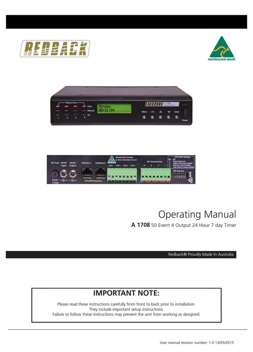
Redback S0080 User manual

User manual revision number: 1.1 29/11/2022
Operating Manual
S0080 50 Event 24 Hour 7 day Timer - Din Rail
1.0 OVERVIEW
The A S0080 is a 7 day timer housed in a convenient DIN rail housing, which has four closing contact outputs. It permits a
total of 50 station (event) switching times. Each can be set to turn on any single day of the week or on multiple days, from
1 sec up to 24 hours. Switching events programmed for multiple days count as only a single station (event) and each of
the 50 event times may be set to any (but not multiple) output.
Manual override is provided so that any of the four outputs can be set “ON” or “OFF” manually which overrides any of
the event times programmed for that output.
The unit has security lock out of Time Edit, Station Edit and Clear Memory Functions via DIP switch selection.
2.0 OPERATION
On the front of the timer there are four LED’s and ve switches which provide a visual indication of the status of each of
the four output zones and provide navigation of the programming menu (Refer to Fig 2.1).
The LED’s indicate whether a zone is in “Auto” mode or “Manual’ mode. A green LED indicates a zone is in “Auto” mode,
and will therefore follow the programmed sequence of triggers entered by the user.
A blue LED indicates that a zone is in “Manual” mode and therefore has been manually set to be either “ON” or “OFF” by
the user. Once a zone is in “Manual” mode it will stay in this mode until the user sets it back to “Auto” mode, or the unit
is switched off (NOTE : All zones will return to ‘Auto Mode’ on power up).
The switches are used to navigate the programming menu, while the switch LED’s indicate the output status of the zone.
i.e. if the zone is “On” or “Off”.
On the rear of the unit are the four, output zone “voltage free” closing contacts. Provision has been included for a normal-
ly open and a normally closed contact on each output.
If a zone is set to “ON” the corresponding output zone will become active. The normally open (N/O) contact for that zone
will short, the normally closed contact (N/C) will become open and these contacts will stay this way until the zone is again
set “OFF”.

Redback® Proudly Made In Australia2
3.0 CONNECTIONS
Figure 3.1 shows the layout of the S0080.
Fig 3.1
3.1 24V DC Connectors
The unit is powered by 24V DC. Connection can be made via a 2.1mm DC jack or screw terminals. These two inputs are
connected in parallel inside the unit, so either could be used as an input, while the other could be used as a 24V DC out-
put to power another device.
Fig 3.2
SPECIAL NOTE ABOUT “AUTO MODE” OPERATION
If the timer is not displaying the main clock screen, where the time is changing, the unit is
not running in “Auto Mode”. This means it will not be checking any of the programmed
events and hence will not activate any outputs automatically.
Essentially this means that as soon as the Menu button is pressed the unit is no longer in
“Auto Mode”.
Make sure to return to the main screen by exiting all menu’s when not making changes.
7 Day 24 Hour Timer
MenuUp Down Enter+10
ZONE MODE
Manual Mode
Auto Mode
Press Zone buttons to
change Zone Mode
S 0080
24VDC
Input
24VDC
Input
+
-
DIP Switches Under
Auto/Manual Mode
LED Indicators
Zone 1 Zone 2 Zone 3 Zone 4
Output Closing Contacts
Zone On/O
Indicators
Top Screw Cover
Bottom Screw Cover
OUTPUT 4
OUTPUT 3
OUTPUT 2
OUTPUT 1
N/O N/C
COM
N/O N/C
COM
N/O N/C
COM
N/O N/C
COM
24V DC Input
(2.1mm Jack)
24V DC Input
(screw terminals)
Acces to DIP
Switches

Redback® Proudly Made In Australia 3
IMPORTANT NOTE:
Ensure power is switched off when adjusting DIP switches.
New settings will be effective when power is switched back on.
3.2 DIP Switch Settings
There are four DIP switches accessible on the inside of the S 0080 which are for selecting the backup battery and various
security lockout features (See Fig 3.3). To access the DIP switches remove the bottom screw cover.
Switch 1 - Battery Backup
When switch 1 is set to the “ON” position the internal battery is connected to the units clock chip. If power is ever
removed the battery will ensure the clock chip continues to run and therefore keep the current time.
NOTE : This battery does not provide backup power to the entire S 0080 unit. The display will not light up and the unit
will not function. Only the internal clock chip will still be supplied power.
If the entire S 0080 requires backup power a backup power supply can be connected to the 24V DC input.
Switch 2 - Station Edit Lockout
When switch 2 is set to “ON” access to the Station Edit Mode will be restricted. Therefore there can be no tampering of
the Station (Event) times.
Switch 3 - Time Edit Lockout
When switch 3 is set to the “ON” access to the Time Edit Mode will be restricted. Therefore there can be no changes
made to the current time.
Switch 4 - Clear Memory Lockout
When switch 4 is set to the “ON” access to the Clear Memory Mode will be restricted. Therefore there can be no erasing
of the Station (Event) times stored in memory.
DIP Switch Settings
SW ON
1
2
Station Edit Lockout Enabled
3
Edit Time Lockout Enabled
4
Clear Memory Lockout Enabled
Battery Backup On
Fig 4.1

Redback® Proudly Made In Australia4
Fig 3.4
3.3 Closing Contacts:
These contacts “close” when the corresponding output zone is set “ON”.
(Note: these relay contacts are voltage free and have a rating of 1 amp).
These can be used to trigger devices such as the Redback A 1741 MP3 Message player, which require a closing contact
to activate. Or they could be used to trigger external relays to switch power to external devices.
Fig 3.4 illustrates an example of connecting the S 0080 to the triggers of an A 1741, and also using an S 4455 high cur-
rent relay box to switch an external power supply.
A 24V DC plugpack is used to power the S 0080 and another to power the A 1741, although a single 1A 24V DC supply
would be sufcient to power both.
In the example shown the Zone Output 1 closing contact of the timer is connected to the Input 1 trigger of the A 1741
message player. When Zone1 is activated by the timer, the normally open contact closes and triggers input 1, subsequently
playing message 1 of the message player.
With the addition of the Redback S 4455 10 amp relay box we can switch as external supply to power a high current
drawing device. The S 4455 can be set to 12/24/48V operation (in this case we have set it to 24V) via the on board jump-
er. We then use ouput 4 of the timer to switch the positive side of the 24V supply, to power the S4455 relay box. The 24
V in this case is being piggy backed off the supply from the timer (but a separate power supply could be substituted).
Hence when output 4 is triggered by the timer, power is applied to the S 4455 relay box. The normally open contact on
the S 4455 therefore closes and power is then switched from the external supply to the external device (in this case a
pump, solenoid, etc).
S 4455 Relay Box
Voltage Free Contacts
N/O1
N/C1
COM1
N/O2
N/C2
COM2
DC Input
Voltage
+
Relay On
DC Voltage
Selector
12V
24V
48V
4
L
R
Line Out
12-30V DC
Switched
Out
12-30V DC
IN
1
www.altronics.com.au
Manufactured in Australia
By Altronic Distributors Pty. Ltd.
1 2 3 4 5 6 7 8
2
3567
8
Alert
Cancel
DIP Switch Settings
ON OFF
1Triggers momentary Triggers alternate
2Alert/Evac ON
Not Used
SW
TRIGGER OPERATION & ALERT/EVAC SETTINGS
DIP Switches
Evac
Triggers
Close
Contacts
to
Trigger
50101010101010101
60011001100110011
70000111100001111
80000000011111111
Delay
(Sec.)
OFF
30
60
90
120
150
180
210
240
270
300
330
360
390
420
450
AUTO ALERT TO EVAC SWITCHOVER TIMER SETTINGS. 0 = OFF. 1 = ON.SW
3Front switches active Front switches de-activated
4
Alert/Evac OFF
+
–
+
-
1 2 3 4 5 6 7 8
24V DC Plugpack
(such as M 8968B)
S 0080
50 EVENT TIMER
A 1741
MP3 Message Player
S 4455
10 Amp 12/24/48V
Relay box
External
24V DC Supply
+24V
GND
_
_
7 Day 24 Hour Timer
MenuUp Down Enter+10
ZONE MODE
Manual Mode
Auto Mode
Press Zone buttons to
change Zone Mode
S 0080
24VDC
Input
24VDC
Input
+
-
DIP Switches Under
Zone 1 Zone 2 Zone 3 Zone 4
OUTPUT 4
OUTPUT 3
OUTPUT 2
OUTPUT 1
N/O N/C
COM
N/O N/C
COM
N/O N/C
COM
N/O N/C
COM
Output relays
1 amp rating
24V DC Plugpack
(such as M 8968B)
Output relays
10 amp rating
Pump,
Solenoid,
etc

Redback® Proudly Made In Australia 5
4.0 BATTERY BACKUP
Inside the unit is the battery used to backup the internal clock chip. If DIP switch 1 (battery backup) is set to “ON” and the
unit fails to keep the correct time after a power failure then it may be possible that the backup battery is at. To replace
the battery, remove the rear of the DIN rail enclosure using a small at blade screwdriver.
Inside you will nd two boards which are screwed together. Carefully removed these from the DIN rail enclosure.
Fig 4.1 Fig 4.2
The battery required is a 3V Lithium (CR2032) such as Redback S 4999B and is mounted in a vertical mount battery holder
as shown in gures 5.1 and 5.2.
Fig 4.3 Fig 4.4
Remove the screws highlighted in gure 5.3 and then remove the top board, so that the battery is accessible as shown in
gure 5.4.
Replace the battery and then reverse the procedure to assemble the unit back together. Make sure the header pins
highlighted in gure 5.4 are lined up correctly before screwing the boards back together.

Redback® Proudly Made In Australia6
3.0 NAVIGATING THE MENUS
In order to setup the unit to run automatically, the station (or event) times will need to be programmed. There are ve
buttons on the front of the timer which are used to program the unit and navigate the various menus.
When the unit is rst powered up, the model number and Chipset will be displayed briey before the current time is
shown IN gure 3.1.
The main screen (Current Time Screen) shown in Fig 3.2 displays the current time. When this screen is displayed the unit
is running in “AUTO MODE” and therefore all outputs will work as programmed. However if the unit is in any of the sub
menu’s (Menu Mode) the unit will no longer respond to any event that has been programmed to occur, while the unit
remains in menu mode. On exiting the menu, the
timer will check all programmed events and update
the status of the output zones.
Press the “Menu” button on the front of the timer.
The unit is now in “Menu Mode” and the screen
should display the Manual Select of Output Zones
Screen. This is the rst of 5 sub menu screens which
are navigated by pressing the up and down buttons
as shown in Fig 3.3. Pressing the Menu button again
will return the user to the Main Screen. Select the
desired sub menu by pressing the “Enter” button.
3.1 SUB MENU’S
There are 4 options to choose from.
1) Manual Selection Of Output Zones
2) Add or Edit A Station Time
3) Edit Time on Clock
4) Clear Memory of ON/OFF Times
3.1.1 Manual Selection OF Output Zones
QUICK ACCES MANUAL OPERATION
On
After selecting this option the screen should appear as shown in Fig 3.4. The square brackets indicate the cursor position
on the screen.
Fig 3.1
Monday
07:00:00 Fig 3.2
1) Manual select
of output zones
2) Add or edit a
Station time
3) Edit time
on clock
4) Clear memory
of ON/OFF times.
5) Exit Main Menu
Monday
07:00:00
Menu
Main Screen
Press the UP and DOWN
buttons to scroll up and
down.
Enter Press the ENTER
button to make your
selection
Menu Press the MENU
button to exit at any
time.
OUTPUT 1
[AUTO] ON OFF Fig 3.4
Altronics S 0080
DS3231 Chipset 1
Fig 3.3

Redback® Proudly Made In Australia 7
Enter
Manual Selection Screen
OUTPUT 1
[AUTO] ON OFF
OUTPUT 1
AUTO [ON] OFF
OUTPUT 1
AUTO ON [OFF]
1) Manual select
of output zones
OUTPUT 2
[AUTO] ON OFF
OUTPUT 2
AUTO [ON] OFF
OUTPUT 2
AUTO ON [OFF]
OUTPUT 3
[AUTO] ON OFF
OUTPUT 3
AUTO [ON] OFF
OUTPUT 3
AUTO ON [OFF]
OUTPUT 4
[AUTO] ON OFF
OUTPUT 4
AUTO [ON] OFF
OUTPUT 4
AUTO ON [OFF]
Exit Manual
Zone Selection
Press the UP and DOWN
buttons to scroll up and
down.
Enter Press the ENTER
button to make your
selection
Menu Press the MENU
button to exit at any
time.
Fig 3.5
SPECIAL NOTE FOR FIRST TIME USE:
When powering up the unit for the rst time it will be necessary to
clear the memory before entering any Station (Event) times. If this is not
done the unit will not operate correctly. To do this use option 4 in the
menu. Refer to the section on “Clearing the Memory”.
Navigate to the “Add or Edit a Station Time” Sub Menu as shown in Fig 3.3. If this is the rst time entering this menu the
screen should appear as shown in Fig 3.6. The number “1)” shown is the Station (or Event) number which is highlighted
by a ashing cursor.
3.1.2 Add or Edit A Station Time
This option allows the user to enter the Station (Event ) information which includes the event “Turn on time”, “Duration”
and “Output Zone”.
If this is the rst time an Event has been entered the memory will need to be “Cleared” rst. To do this follow the
directions in the section “Clearing the Memory”.
1) - DAY
Start @ 00:00:00 Fig 3.6
To set a Zone manually, scroll to the desired zone using the up and down buttons as shown in Fig 3.5 and then press
“Enter” when you reach your selection. When nished scroll to the “Exit Manual Zone Selection” screen and press
“Enter” or press the “Menu” button to exit at any time. (NOTE: For the unit to continue in “AUTO MODE” you must exit
back to the Main Screen.)
SPECIAL NOTE:
If power is removed, all outputs will switch off and all zones will
return to Auto mode once power is restored.

Redback® Proudly Made In Australia8
From this point the user can scroll through all 50 stations using the up and down buttons as shown in g 3.7. This makes
it very easy to view all Station time settings at a glance. Once the station number desired is shown on the LCD press the
“Enter” button to conrm and move to the next step which is to make changes to the station “day”.
Fig 3.7
Enter
Press the UP and DOWN
buttons to scroll up and
down.
Enter Press the ENTER
button to make your
selection
Menu Press the MENU
button to exit at any
time.
2) Add or edit a
Station time
50) - DAY
Start @ 00:00:00
1) - DAY
Start @ 00:00:00
2) - DAY
Start @ 00:00:00
3) - DAY
Start @ 00:00:00
49) - DAY
Start @ 00:00:00
Station (or Event) number
Press the +10 button to
scroll up 10 stations
+10
The DAY represents the day of the week that the Event will take place and can be any day from Monday to Sunday or
one of many multiple day options which are listed below. Pressing the up and down buttons will scroll through the days
monday to friday and then through the multiple days.
Mon-Fri
Sat-Sun
Mon/Wed/Fri
Tue/Thu/Sat
Mon-Thur
Mon-Sun
Tue-Fri
Mon/Fri
Tue/Wed/Thu
Mon/Wed
Mon/Thur
Mon/Tue/Thu
Tue/Thur
Tue/Wed/Fri
Tue/Thu/Fri
Wed/Fri
Mon/Tue/Wed
Press the UP and DOWN
buttons to scroll up and
down.
Enter Press the ENTER
button to make your
selection
Menu Press the MENU
button to exit at any
time.
1) Mon/Tue/Wed
Start @ 00:00:00
1) Monday
Start @ 00:00:00
1) Tuesday
Start @ 00:00:00
1) Wednesday
Start @ 00:00:00
1) - Wed/Fri
Start @ 00:00:00
Day of the week
1) DAY
Start @ 00:00:00
Fig 3.8
Once the day or multiple days desired is shown on the LCD, press the “Enter” button to conrm. The cursor will now
move to the start time. This is the time the “Event” is to take place and is in 24 hour format.

Redback® Proudly Made In Australia 9
The cursor is now positioned over the hour section of the start time as shown in Fig 3.9.
Press the UP and DOWN
buttons to change the
hour/min/secs.
Enter Press the ENTER
button to make your
selection
Menu Press the MENU
button to exit at any
time.
1) Monday
Start @ 23:00:00
1) Monday
Start @ 00:00:00
1) Monday
Start @ 01:00:00
1) Monday
Start @ 02:00:00
1) Monday
Start @ 22:00:00
Start time
1) Monday
Start @ 00:00:00
Press the +10 button to
scroll up 10
hours/min/secs
+10
Fig 3.9
Change the hour by pressing the +10, up and down
buttons and press “Enter” when nished. The cursor
will now move to the minute section of the start time.
Repeat the above procedure to change the minutes
and press “Enter” when nished. The cursor will now
move to the seconds section of the start time. Repeat
the above procedure again to change the seconds and
press “Enter” when nished. The start time is now set
for this Station (or Event).
After completing the start time, the screen will change
to the Zone and Duration options screen as shown in
Fig 3.10.
Fig 3.10
1) ZONE DURATION
OFF 00:00:00
From this point the user can scroll through all 50 stations using the up and down buttons as shown in g 3.11. This makes
it very easy to view all Output Zone settings at a glance. Once the station number desired is shown on the LCD press the
“Enter” button to conrm and move to the next step which is to make changes to the zone output.
Fig 3.11
Enter
Press the UP and DOWN
buttons to scroll up and
down.
Enter Press the ENTER
button to make your
selection
Menu Press the MENU
button to exit at any
time.
Station (or Event) number
Press the +10 button to
scroll up 10 stations
+10
1) ZONE DURATION
OFF 00:00:00
1) ZONE DURATION
OFF 00:00:00
2) ZONE DURATION
OFF 00:00:00
3) ZONE DURATION
OFF 00:00:00
49) ZONE DURATION
OFF 00:00:00
50) ZONE DURATION
OFF 00:00:00

Redback® Proudly Made In Australia10
Press the UP and DOWN
buttons to change the
zone output.
Enter Press the ENTER
button to make your
selection
Menu Press the MENU
button to exit at any
time.
Zone Output
1) ZONE DURATION
1 00:00:00
1) ZONE DURATION
2 00:00:00
1) ZONE DURATION
3 00:00:00
1) ZONE DURATION
OFF 00:00:00
1) ZONE DURATION
4 00:00:00
Fig 3.12 illustrates the Zone Output setup procedure. There are 4 output zones to choose from. Use the up and down
buttons to change the zone output and press “Enter” when nished. The zone can also be set to “OFF” which will turn
this output off, but not affect the time settings so that it can easily be re-initiated by setting the zone output later.
Fig 3.12
The cursor is now positioned over the hour section of the Zone Duration as shown in Fig 3.13. The duration is the amount
of time the event will occur for, after the start time.
Fig 3.13
Change the hour by pressing the +10, up and down
buttons and press “Enter” when nished. The cursor
will now move to the minute section of the duration.
Repeat the above procedure to change the minutes
and press “Enter” when nished. The cursor will now
move to the seconds section of the duration. Repeat
the above procedure again to change the seconds and
press “Enter” when nished. The menu button can be
pressed at any time to exit the setup. The duration is
now set for this Station (or Event).
After completing the duration, the screen will change to
the next station ready to enter the next events details.
NOTE: IF the duration is set to 00:00:00 the zone
output will be set back to “OFF” on exiting the “Set
Duration” screen.
Press the UP and DOWN
buttons to change the
hour/min/secs.
Enter Press the ENTER
button to make your
selection
Menu Press the MENU
button to exit at any
time.
Zone Duration
Press the +10 button to
scroll up 10
hours/min/secs
+10
1) ZONE DURATION
1 00:00:00
1) ZONE DURATION
1 00:00:00
1) ZONE DURATION
1 01:00:00
1) ZONE DURATION
1 02:00:00
1) ZONE DURATION
1 22:00:00
1) ZONE DURATION
1 23:00:00

Redback® Proudly Made In Australia 11
3.1.3 Edit the Clock Time
This option sets the current time.
After selecting the “Edit Time on Clock” option from the menu
shown in Fig 3.3 the LCD will display the screen shown in Fig 3.13
where the cursor ashes on the current day.
Pressing the up and down buttons will scroll through the days Mon-
day to Sunday. Pressing “Enter” will conrm the day and then move
the cursor to the hour option as shown in Fig 3.14.
Change the hour by pressing the +10, up and down buttons and
press “Enter” when nished. The cursor will now move to the
minute section of the clock time. Repeat the above procedure to
change the minutes and press “Enter” when nished. The cursor
will now move to the seconds section of the clock time. Repeat the
above procedure again to change the seconds and press “Enter”
when nished. The menu button can be pressed at any time to exit
the setup. The clock time is now set.
After completing the clock time, the screen will change to the
current time.
3.1.4 Clearing the Memory
This function will clear the internal memory, erasing any
information
entered.
Navigate to the “Clear Memory of ON/OFF times” Sub Menu as
shown in Fig 3.3.
Press “Enter” to activate this option. If DIP switch 4 is set to “ON”
the screen will display the message shown in Fig 3.15.
This is one of the security options to protect the information stored
in memory. See the DIP Switch settings for more
information. Set the DIP switch 4 to “OFF” and then press “Enter”
again. This time you should enter the Clearing the Memory Sub
Menu. The following two screens should be briey displayed.
Then you will be asked to press “Enter” to conrm you want to clear the memory or press “Menu” to exit.
If you press Menu you will return to the Clear Memory Sub Menu.
If you press Enter, the unit will cycle through the memory locations clearing any data stored. This will take a few minutes.
Once nished you will return back to the Clear Memory Sub Menu.
NOTE: It is advisable to now set DIP switch 4 to “ON” to prevent accidental clearing of the memory.
Not Available
Check Settings Fig 3.15
This will clear
all ON/OFF times
Are you sure?
Hold ENTER for Y
or MENU for No
Press the UP and DOWN
buttons to change the
hour/min/secs.
Enter Press the ENTER
button to make your
selection
Menu Press the MENU
button to exit at any
time.
Clock Time
Monday
00:00:00 Edit
Monday
01:00:00 Edit
Monday
02:00:00 Edit
Monday
22:00:00 Edit
Monday
23:00:00 Edit
Press the +10 button to
change the
hour/min/secs.
+10
Press the UP and DOWN
buttons to change the
day.
Enter Press the ENTER
button to make your
selection
Menu Press the MENU
button to exit at any
time.
Clock Day
Monday
00:00:00 Edit
Tuesday
00:00:00 Edit
Wednesday
00:00:00 Edit
Saturday
00:00:00 Edit
Sunday
00:00:00 Edit
Enter
3) Edit time
on clock
Fig 3.13
Fig 3.14
IMPORTANT NOTE:
The memory must be cleared before using
the unit for the rst time.

Redback® Proudly Made In Australia12
7.0 EVENT TIMES RECORD
A sheet has been provided to record all of the Event(s) information for easy reference.
STATION OUTPUT DAY TURN ON TIME DURATION TURN OFF TIME
1
2
3
4
5
6
7
8
9
10
11
12
13
14
15
16
17
18
19
20
21
22
23
24
25
26
27
28
29
30
31
32
33
34
35
36
37
38
39
40
41
42
43
44
45
46
47
48
49
50
OUTPUT 1 = OUTPUT 2 =
OUTPUT 3 = OUTPUT 4 =
Table of contents
Other Redback Timer manuals

Redback
Redback A 1709 User manual

Redback
Redback A 1700 User manual

Redback
Redback A 4505C User manual

Redback
Redback A 2064 User manual

Redback
Redback A 4500C User manual

Redback
Redback A 1708 User manual

Redback
Redback A 4500C Operating instructions

Redback
Redback A 4505B User manual

Redback
Redback A 4510A User manual

Redback
Redback A 4505 User manual