RedMax AG4300 Owner's manual

The engine exhaust from this product
contains chemicals known to the State
of California to cause cancer, birth
defects or other reproductive harm.
WARNING
OWNER/OPERATOR MANUAL
POWER AUGER
T4507-93110 (603)
AG4300
Thank you for purchasing a RedMax
product.
Before using our power auger, please
read this manual carefully to understand
the proper use of your unit.
(NOTE: Drill is optional part.)
APPLICABLE SERIAL NUMBERS : 100101 and up

Read this manual carefully to understand
all safety precautions, controls, proper
operation and maintenance of your
RedMax power auger. Failure to do so
could result in serious injury.
Instructions labeled as shown at left concern critical steps or
procedures which must be followed in order to prevent
accidents which could lead to serious bodily injury or death.
This mark is used to indicate instructions which must be
followed without exception.
Instructions labeled as shown at left concern steps or
procedures which, if not followed correctly, could lead to
mechanical failure, breakdown, or damage.
Used to label supplementary instructions designed to provide
hints or directions useful in the use of the product.
SAFETY FIRST
Instructions contained in warnings within this manual marked with a symbol
concern critical points which must be taken into consideration to prevent
possible serious bodily injury, and for this reason you are requested to read all
such instructions carefully and follow them without fail.
Note that there may be times when warning seals peel off or become soiled and
impossible to read. If this happens, you should contact the dealer from which
you purchased the product to order new seals and affix the new seal(s) in the
required location(s).
■ Notes on types of warnings
WARNING
IMPORTANT
NOTE

CONTENTS
1. SAFETY PRECAUTIONS .............................................................................. 4
IN ORDER TO ENSURE PROPER AND SAFE OPERATION OF YOUR POWER AUGER
WORK GEAR AND CLOTHING
WARNINGS CONSIDERING HANDLING OF FUEL
THINGS TO CHECK BEFORE USING YOUR POWER AUGER
THINGS TO CHECK BEFORE STARTING UP THE ENGINE
AVOID NOISE PROBLEM
THINGS TO BE CAREFUL ABOUT WHEN USING YOUR POWER AUGER
NOTES ON CARE AND MAINTENANCE OF YOUR POWER AUGER
2. FUEL .............................................................................................................. 9
HOW TO MIX FUEL
FUELING THE UNIT
3. OPERATION ................................................................................................. 11
INSTALLING LEFT GRIP
INSTALLING DRILL
THROTTLE CABLE PLAY
STARTING ENGINE
STOPPING ENGINE
DRILLING
ADJUSTING CARBURETOR
4. MAINTENANCE ........................................................................................... 14
DAILY INSPECTION
PERIODICAL INSPECTION
5. STORAGE .................................................................................................... 16
BEFORE LONG-TERM STORAGE
6. SPECIFICATIONS ........................................................................................ 16
7. PARTS LIST ................................................................................................. 17

4
■In order to ensure proper and safe
operation of your power auger
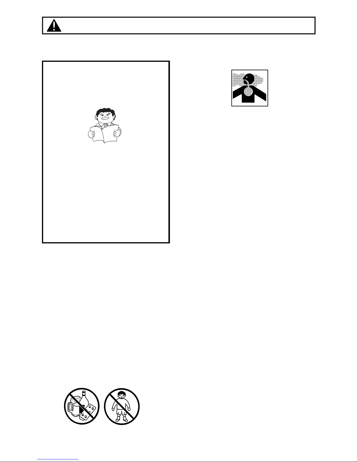
•Read this Owner/Operator Manual
carefully. Be sure you understand how
to operate this unit properly before you
use it. Failure to do so could result in
serious injury.
•Be sure to keep this manual handy so
that you may refer to it later whenever
any questions arise. Also note that you
are requested to contact the dealer from
whom you purchased the product for
assistance in the event that you have
any questions which cannot be
answered herein.
•Always be sure to include this manual
when selling, lending, or otherwise
transferring the ownership of this
product.
•This product has been designed for use in
earth drilling, and it should never be used
for any other purpose since doing so
could result in unforeseen accidents and
injuries occurring.
•You should never use this power auger
when under the influence of alcohol, when
suffering from exhaustion or lack of sleep,
when suffering from drowsiness as a
result of having taken cold medicine, or at
any other time when a possibility exists
that your judgment might be impaired or
that you might not be able to operate the
power auger properly and in a safe
manner. Also be sure never to allow
children or anyone unable to fully
understand the directions given in this
manual to use this power auger.
1. Safety Precautions
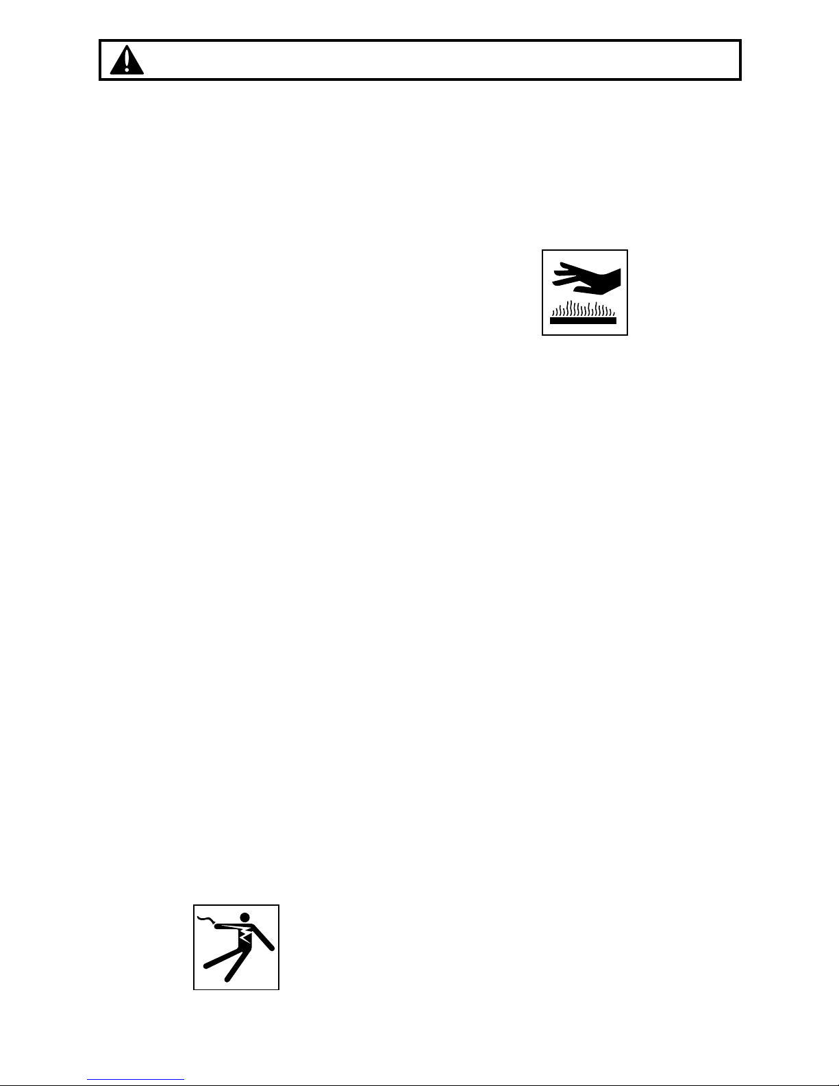
•Avoid running the engine indoors. The
exhaust gases contain harmful carbon
monoxide.
•Never use your power auger under
circumstances like those described below:
1. When the ground is slippery or when
other conditions exist which might
make it not possible to maintain a
steady posture while using the power
auger.
2. At night, at times of heavy fog, or at any
other times when your field of vision
might be limited and it would be difficult
to gain a clear view of the area where
the power auger is to be used to ensure
safety.
3. During rain storms, during lightning
storms, at times of strong or gale-force
winds, or at any other times when
weather conditions might make it
unsafe to use this product.
•When using this product for the first time,
before beginning actual work, take the
power auger to a wide, clear, open space,
turn on the power, and practice handling
the power auger until you are sure that
you will be able to handle in it properly in
actual operation.
•Lack of sleep, tiredness, or physical
exhaustion results in lower attention
spans, and this in turn leads to accidents
and injury. When planning your work
schedule, allow plenty of time to perform
the work of cutting and allow plenty of
time for rest. Limit the amount of time
over which the power auger is to be used
continuously to somewhere around 30~40
minutes per session, and take 10~20
minutes of rest between work sessions.
Also try to keep the total amount of work
performed in a single day under 2 hours
or less.

■Work gear and clothing
•When using your power auger, always be
sure to wear strong, durable, work
clothing; shirts should be long-sleeved
shirts and pants should be full-length
pants reaching down to the ankles.
•Always be sure to wear and helmet and
face protector when using your power
auger.
•When using your power auger, always be
sure to wear thick work gloves to protect
your hands and non-slip-sole work boots
to prevent you from slipping. Never use
your power auger when wearing pants
with loose cuffs, when wearing sandals, or
when barefoot.
•When using your power auger for an
extended period of time, you should wear
ear protectors to protect yourself from loss
of hearing from overexposure to high
levels of sound.
■Warnings considering handling of fuel
•The engine of the power auger is
designed to run on a mixed fuel which
contains highly flammable gasoline. This
fuel is highly flammable and you should
never store cans of fuel or refill the tank of
the power auger in any place where there
is a boiler, stove, wood fire, electrical
sparks, welding sparks, or any other
source of heat or fire which might ignite
the fuel.
•Smoking while operating the power auger
or refilling its fuel tank is extremely
dangerous. Always be sure to keep lit
cigarettes away from the power auger at
all times.
•When refilling the tank always turn off the
engine first and take a careful look around
to make sure that there are no sparks or
open flames anywhere nearby before
refueling.
•If any fuel spillage occurs during refueling,
always be sure to use a dry rag to wipe
any fuel which has been spilled onto the
power auger before turning the engine
back on again.
•After refueling, screw the fuel cap back
tightly onto the fuel tank and then carry
the power auger to a spot 10 feet or more
away from where it was refueled before
turning on the engine.
5
1. Safety Precautions

6
■Things to check before using your
power auger
•Before beginning work, look around
carefully to get a feel for the shape of the
land, and whether or not there are any
obstacles which might get in the way while
working, and remove any obstacles which
can be cleared away before beginning
work.
•The area within a perimeter of 45 feet of
the person using the power auger should
be considered a hazardous area into
which no one should enter while the
power auger is in use, and when
necessary yellow warning rope, warning
signs, or some other form of warnings
should be placed around the perimeter of
the area. When work is to be performed
simultaneously by two or more persons,
care should also be taken to constantly
look around or otherwise check for the
presence and locations of other people
using power auger within the work area so
as to maintain a distance between each
person sufficient to ensure safety.
•Before beginning work, each component
of the power auger should be checked to
make sure that it is in proper working
order and to make sure that there are no
loose screws or bolts, fuel leaks, ruptures,
dents, or any other problems which might
interfere with safe operation. Be especially
careful at this time to check that there is
nothing wrong with the drills or with the
joints by which the drills are attached to
the power auger.
■Things to check before starting up the
engine
•Take a careful look around to make sure
that no obstacles exist within a perimeter
of 15 feet or less around the power auger
before starting the engine.
•The power auger is equipped with a
centrifugal clutch mechanism which
causes the drills to begin to rotate as soon
as the engine is started by putting the
throttle into the start position. When
starting the engine, hold it firmly in place
so as to ensure that nor the throttle may
not come into contact with any obstacles
when the engine starts up.
•Never place the throttle into the high
speed position when starting the engine.
•After starting up the engine, check to
make sure that the drills stop rotating
when the throttle is moved fully back to its
original position. If the drills continue to
rotate even after the throttle has been
moved fully back, turn off the engine and
take the unit to your authorized Red Max
servicing dealer for repair.
■Avoid noise problem
Check and follow the local regulations as
to sound level and hours of operations
for power auger.
•In general, operate power auger between
8a.m.and 5p.m.on week days and 9a.m.to
5p.m.weekends. Avoid using power auger
late at night and/or early in the morning.
NOTE
1. Safety Precautions

■Things to be careful about when using
your power auger
•When using your power auger, grip the
handles of the power auger firmly with
both hands, place your feet slightly apart
(slightly further apart than the width of
your shoulders) so that your weight is
distributed evenly across both legs, and
always be sure to maintain a steady, even
posture while working.
•Maintain the speed of the engine at the
level required to perform drilling work, and
never raise the speed of the engine above
the level necessary.
•Always be sure never to allow other
persons to come within the work area
while drilling.
•Be especially careful not to slip if it is
raining or if rain has just stopped, as the
ground is likely to be slippery at such
times.
•If the grass or other object gets caught in
the drill during operation, always be sure
to turn off the engine before removing the
object.
•Guard against hazardous situations at all
times. Warn adults to keep pets and
children away from the area. Establish a
safe method for gaining your attention
during operation. Be careful if you are
approached.
•If someone calls out or otherwise
interrupts you while working, always be
sure to turn off the engine before turning
around.
•Keep operation area clear of all persons,
particularly small children and pets.
•Never touch the spark plug or plug cord
while the engine is in operation. Doing so
may result in being subjected to an
electrical shock.
•Never touch the muffler, spark plug, or
other metallic parts of the engine while the
engine is in operation or immediately after
shutting down the engine. These metallic
parts reach high temperatures during
operation and doing so could result in
serious burns.
•When you finish drilling in one location
and wish to continue work in another spot,
turn off the engine before carrying it to the
new location.
•Never transport the power auger over
rough roads over long distances without
first removing all fuel from the fuel tank, as
doing so might cause fuel to leak from the
tank as a result of shocks absorbed during
transport.
7
1. Safety Precautions

8
■Notes on care and maintenance of your
power auger
•In order to maintain your power auger in
proper working order, perform the
maintenance and checking operations
described in this manual at regular
intervals. In the event that any parts must
be replaced or any maintenance or repair
work not described in this manual must be
performed, please contact a
representative from the store nearest
RedMax authorized servicing dealer for
assistance.
•Under no circumstances should you ever
take apart the power auger or alter it in
any way. Doing so might result in the
power auger becoming damaged during
operation or the power auger becoming
unable to operate properly.
•Always be sure to turn off the engine
before performing any maintenance or
checking procedures.
•When removing, or reattaching the drills,
be sure to wear thick, sturdy gloves and
use only proper tools and equipment to
prevent injury.
•When replacing drills or any other parts or
when replacing the oil or any lubricants,
always be sure to use only RedMax
products or products which have been
certified by RedMax for use with the
power auger.
•Do not use any accessory or attachment
other than those bearing the RedMax
mark and recommended for the unit.
1. Safety Precautions

2. Fuel
9
■RECOMMENDED MIXING RATIO
GASOLINE 50:OIL 1
(when using ZENOAH genuine oil)
•Exhaust emission are controlled by the
fundamental engine parameters and
components(eq., carburation, ignition
timing and port timing) without
addition of any major hardware or the
introduction of an inert material during
combustion.
•These engines are certified to operate on
unleaded gasoline.
•Make sure to use gasoline with a
minimum octane number of 89 RON
(USA/Canada: 87AL)
•If you use a gasoline of a lower octane
value than prescribed, there is a danger
that the engine temperature may rise and
an engine problem such as piston seizing
may consequently occur.
•Unleaded gasoline is recommended to
reduce the contamination of the air for the
sake of your health and the environment.
•Poor quality gasolines or oils may damage
sealing rings, fuel lines or fuel tank of the
engine.
■HOW TO MIX FUEL
Pay attention to agitation.
1. Measure out the quantities of gasoline
and oil to be mixed.
2. Put some of the gasoline into a clean,
approved fuel container.
3. Pour in all of the oil and agitate well.
4. Pour In the rest of gasoline and agitate
IMPORTANT
•Gasoline is very flammable. Avoid
smoking or bringing any flame or
sparks near fuel. Make sure to stop the
engine and allow it cool before
refueling the unit. Select outdoor bare
ground for fueling and move at least
3m (10ft) away from the fueling point
before starting the engine.
•The RedMax engines are lubricated by oil
specially formulated for air-cooled 2-cycle
gasoline engine use. If RedMax oil is not
available, use an anti-oxidant added
quality oil expressly labeled for air-cooled
2-cycle engine use. (JASO FC GRADE
OIL or ISO EGC GRADE)
•Do not use BIA or TCW (2-stroke water-
cooling type) mixed oil.
WARNING
50:1 MIXING CHART
GASOLINE gal. 1 2 3 4 5
2-CYCLE OIL fl.oz 2.6 5.2 7.8 10.4 13
GASOLINE liter 1 2 3 4 5
2-CYCLE OIL ml 20 40 60 80 100

5. In the case of storing the product for a
long period of time, clean the fuel tank
after rendering it empty. Next, activate the
engine and empty the carburetor of the
composite fuel.
6. In the case of scrapping the used mixed
oil container, scrap it only at an authorized
repository site.
As lot details of quality assurance, read the
description in the section Limited Warranty
carefully. Moreover, normal wear and
change in product with no functional
influence are not covered by the warranty.
Also, be careful that, if the usage in the
instruction manual is not observed as to the
mixed gasoline, etc. described therein, it
may not be covered by the warranty.
NOTE
again for at least one minute. As some
oils may be difficult to agitate depending
on oil ingredients, sufficient agitation is
necessary for the engine to last long. Be
careful that, if the agitation is insufficient,
there is an increased danger of early
piston seizing due to abnormally lean
mixture.
5. Put a clear indication on the outside of the
container to avoid mixing up with gasoline
or other containers.
6. Indicate the contents on outside of
container for easy identification.
■FUELING THE UNIT
1. Untwist and remove the fuel cap. Rest the
cap on a dustless place.
2. Put fuel into the fuel tank to 80% of the full
capacity.
3. Fasten the fuel cap securely and wipe up
any fuel spillage around the unit.
1. Select bare ground for fueling.
2. Move at least 10feet (3meters) away
from the fueling point before starting
the engine.
3. Stop the engine before refueling the
unit. At that time, be sure to sufficiently
agitate the mixed gasoline in the
container.
FOR YOUR ENGINE LIFE, AVOID;
1. FUEL WITH NO OIL(RAW GASOLINE) –
It will cause severe damage to the internal
engine parts very quickly.
2. GASOHOL – It can cause deterioration of
rubber and/or plastic parts and disruption
of engine lubrication.
3. OIL FOR 4-CYCLE ENGINE USE – It can
cause spark plug fouling, exhaust port
blocking, or piston ring sticking.
4. Mixed fuels which have been left
unused for a period of one month or
more may clog the carburetor and result
in the engine failing to operate properly.
WARNING
2. Fuel
10

3. Operation
■INSTALLING LEFT GRIP (F1)
•Screw in the left grip to the bracket provided on
the frame and tighten the lock nut securely.
(1) Left grip
(2) Bracket
(3) Lock nut
■INSTALLING DRILL (F2)
1. Slide the ring clip and remove the lock pin from
the drill.
2. Put the drill onto the auger output shaft and
insert the lock pin. Cover it with the ring clip.
(1) PTO shaft
(2) Clip band
(3) Drill
(4) Pin
■THROTTLE CABLE PLAY (F3)
•Check the throttle cable play and adjust to
1~2mm(.04~.08in.) as necessary.
(1) Lock nut
(2) Big
(3) Small
■STARTING ENGINE
1. Fill fuel and tighten the cap securely.
2. Put the switch to “START” position. (F4)
3. Close the choke. (F5)
When restarting immediately after stopping the
engine, Ieave the choke open. (F5)
4. Push the primer pump until overflown fuel flows
out in the clear tube. (F5)
The pump operation is not necessary when
restarting the engine immediately after stopping it.
5. Push the start set button of the handle left
NOTE
NOTE
F1
F2
F3
F4
F5
11

3. Operation
aspect while holding the throttle lever, and set
the throttle lever in the start position. (F6)
(1) Engine switch
(2) Start
(3) Stop
(4) Choke lever
(5) Open
(6) Close
(7) Primer pump
(8) Throttle lever
(9) Lock button
6. While supporting the auger with your left waist
and left hand as shown in the figure, pull the
starter rope, first lightly and add force when
compression is felt. (F7)
Keep the drill clear of everything around it as it
will start rotating upon starting of engine.
7. When the engine has started, gradually open the
choke and release the throttle lever.
8. Alow the engine to warm up for a half minutes
before starting operation.
•When re-starting immediately after stopping the
engine, keep the choke open.
•If the engine won’t start after repeated attempts,
it may be overfed with fuel. Remove and dry the
spark plug, and try to start again with the choke
open.
■STOPPING ENGINE
1. Release the throttle lever to allow the engine
idling for a few minutes
2. Put the switch to the “STOP” position. (F8)
(1) Engine switch
■DRILLING (F9)
•Keep a firm grip of the auger at all times on a
wide stance and by holding the handle with both
NOTE
WARNING
F6
F8
F7
12

3. Operation
hands.
•Areacting motion may occur on the auger when
spinning drill has hit on stones or tree roots
under the ground. Always hold the auger
securely to control such motion.
•Start drilling with half-throttle, and gradually
increase the engine speed so that the drill may
get into the ground smoothly.
•When the drill has been caught in the ground
and cannot be pulled out, stop the engine and
rotate the auger counter-clockwise.
■ADJUSTING CARBURETOR (F10,11,12)
The carburetor on your unit has been factory
adjusted, but may require fine tuning due to
change in operating conditions.
Before adjusting the carburetor, make sure that
provided are clean air/fuel filters and fresh,
properly mixed fuel.
1. Stop engine and screw in both H and L needles
until they stop. Never force. Then set them back
the initial number of turns as shown below.
H needle: 13⁄8±1⁄4
L needle: 11⁄4±1⁄4
2. Start engine and allow it to warm up at half-
throttle.
3. Turn L needle slowly clockwise to find a position
where idling speed is maximum, then set the
needle back a quarter (1/4) turn
counterclockwise.
4. Turn idle adjusting screw counterclockwise so
that the drill does not turn. If idling speed is too
slow, turn the screw clockwise.
5. Make a test run and adjust the H needle for best
drilling power, not for maximum speed.
(1) Idle adjusting screw
(2) rpm up
(3) rpmdown
(4) H-needle
(5) Fuel decrease
(6) Fuel increase
(7) L-needle
(8) Fuel decrease
(9) Fuel increase
F10
F11
F12
F9
13

4. Maintenance
Before cleaning, inspecting or repairing the
auger, make sure that the engine has stopped
and cooled down. Disconnect the spark plug
terminal to avoid accidental engine starts.
■DAILY INSPECTION
•Check all nuts and screws are securely tightened
and no parts are missing.
•Check for leakage of fuel.
■PERIODICAL INSPECTION
AIR FILTER (F13)
Check the air filter every 50 hours of use or more
frequently if used under very dusty condition, and
clean the element in warm soapy water as
necessary. Dry completely before installing.
(1) Cover
(2) Element
SPARK PLUG (F14)
Check the spark plug every 50 hours of use and
clean the gap with a wire brush. The gap should be
set to .025 in. When replacing with a new plug, use
a Champion RCJ-6Y or NGK BPMR7A.
FUEL FILTER (F15)
A clogged fuel filter can cause lack of power and
poor pickup. Check the fuel filter every 25 use
hours.
1. With a small wire hook, pull the fuel line and filter
out of tank.
2. Disconnect the filter assembly.
3. If necessary, replace with new filter or clean by
blowing air inside out after spraying a carburetor
cleaning solvent.
(1) Fuel filter
WARNING
F13
F15
.025 in
0.655mm
F14
14
Maintenance, replacement, or repair of the
emission control device and systems may be
performed by any non-road engine repair
establishment or individual.

4. Maintenance
CYLINDER FINS (F16)
Dust clogging between the cylinder fins will cause
overheating of the engine. Periodically check and
clean the cylinder fins.
(1) Intake air cooling vent
SPARK ARRESTER (F17)
This engine is equipped with a spark arresting
screen at the exhaust port. Check periodically to
see if it is good condition, especially when your
machine is to be used on any forest covered, brush
covered, or grass covered unimproved land. In the
State of California the above is required by law
(Section 4442 of the California Public Resources
Code)
1. Remove the muffler guard and pry off the spark
arrester from the exhaust port.
2. Clean the metal screen with a wire brush. If
damaged, replace with new one.
(1) Muffler guard
(2) Spark arrester
GEAR BOX
Check oil level of the gear box every 50 hours of
use and change with new oil as necessary. (SAE
#80 - 90)
Recommended change interval
1st: After 50 hours of use
2nd and on: Every 100 hours of use
(1) Oiling port
(2) Oil drain port
(3) Oil level
CLUTCH
Disconnect the engine from the gear box and
check the clutch condition every 100 hours of use.
Wipe off oil attached to the drum and shoes, and
replace parts with a new one if found to be worn.
F16
F17
F18
15

16
5. Storage
■Before Long-term Storage
•Drain fuel tank and run engine out until all
fuel in the carburetor is used up.
•Remove the spark plug and drop a
spoonful 2 cycle oil into the cylinder.
Crank the engine several times and
replace the plug.
Pull starter until compression is felt.
•Brush off dirt from the drill surface and
apply rust protective oil.
•Store the machine in a dry, dust-free
place.
Model Name ...................................................................................................................AG4300
Engine
Displacement cu.in(cc) ........................................................................................2.53 (41.5)
Maximum power kW(HP) ....................................................................1.5 (2.0) at 7000 rpm
Carburetor ...........................................................................Diaphragm type (Walbro WYK)
ignition system ...............................................................................................Electric (T.C.I)
Spark plug .....................................................................................................NGK BPMR7A
Starter .............................................................................................................Recoil starter
Fuel .............................................................................2 cycle oil premixed gasoline (50:1 )
(when using ZENOAH genuine oil)
Fuel tank capacity fl.oz(lit) .............................................................................................32 (0.94)
Transmission .................................................................Centrifugal clutch, worm gear reduction
Gear box lubricant .......................................................................................Gear oil SAE#80-90
Reduction ratio .....................................................................................................................45:1
Grip span in (mm) .......................................................................................................21.2 (540)
Over all dimensions
Length in (mm) .....................................................................................................24.8 (630)
Width in (mm) .......................................................................................................14.4 (359)
Height w/o drill in (mm) ........................................................................................11.7 (292)
Dry weight w/o drill Ids (kg) ..........................................................................................19.3 (8.9)
Adaptable drill size
Diameter in (mm) ...................................................................................0.8 to 8 (20 to 200)
Specifications are subject to change without notice.
6. Specifications

7. Parts list
NOTE :
1. Use KOMATSU ZENOAH genuine parts as specified in the parts list for repair and/or
replacement.
2. KOMATSU ZENOAH does not warrant the machines, which have been damaged by the
use of any parts other than those specified by the company.
3. When placing parts orders for repair and/or replacement, check if the model name and the
serial number are applicable to those specified in the parts list, then use parts number
described in the parts list.
4. The contents described in the parts list may change due to improvement.
5. The parts for the machine shall be supplied seven (7) years after the machine is
discontinued. [It is possible that some specific parts may be subject to change of their
delivery term and list price within the limit of ten (7) years after the machine is
discontinued. It is also possible that some parts may be available even after the limit of
seven (7) years.]
17
July. 2001
POWER AUGER
AG4300
APPLICABLE SERIAL NUMBERS : 100101 and up

Fig.1 ENGINE UNIT AG4300 (S/N 100101 and up)
18
7. Parts list

19
Fig.1 ENGINE UNIT AG4300 (S/N 100101 and up)
Key# Description Part Number Q'ty
1CYLINDER 848-G6D-12A0 1
2BOLT 1850-12130 4
3GASKET,base 4500-13120 1
4CRANKCASE COMP. 4500-21101 1
5•PIN 2629-21130 3
6GASKET,case 4500-21140 1
7BEARING 06030-06201 2
8OIL SEAL 4810-21210 1
9OIL SEAL 1650-21220 1
10 BOLT 01252-30530 4
11 SNAP RING 04065-03212 1
12 PISTON 4500-41110 1
13 RING 1400-41220 2
14 PIN 2850-41310 1
15 RING 1300-41320 2
16 BEARING T2100-41410 1
17 WASHER 2850-41510 2
18 CRANKSHAFT COMP. 4500-42000 1
19 SHOE,clutch 4500-51111 2
20 SPRING 4500-51220 1
21 SCREW 1200-51211 2
22 WASHER 1200-51230 2
23 WASHER 1200-51241 2
24 ROTOR 4500-71110 1
25 COIL ASS'Y 4500-71200 1
26 • CORD 4500-71220 1
27 • CAP 2616-71320 1
28 • PIN 3356-21130 2
29 GROMMET 5500-72130 1
30 CAP,plug 5500-72110 1
31 SPRING 1900-72120 1
32 BOLT 4500-72150 2
33 NUT 1650-43230 1
34 KEY 1000-43240 1
35 MUFFLER ASS'Y T1007-15100 1
36 • ARRESTER 1601-15120 1
37 BOLT 01252-30565 2
38 BOLT 3310-31720 1
39 GASKET,muffler 4700-15211 1
40 PLATE,muffler 4500-15221 1
41 SCREW 0263-90514 1
42 COVER 4500-31110 1
43 BOLT 3310-12281 4
44 PLATE 4500-31210 1
45 COVER 4500-32110 1
46 SCREW 4500-32120 4
47 GUARD 4500-32210 1
48 SPARKPLUG 5602-73110 1
49 GROMMET 1852-72121 1
50 CORD COMP. T1007-73200 1
51 CLAMP 848-8K4-0010 1
52 RECOIL ASS'Y T1123-75100 1
53 • REEL 4500-75120 1
54 • SCREW 4500-75150 1
55 • SPRING,spiral 1850-75130 1
56 • COLLAR 4500-75180 1
57 • ARM 4500-75190 1
58 • ROPE 4500-75160 1
59 • KNOB 1140-75320 1
60 • PLATE,stopper 5500-75170 1
Key# Description Part Number Q'ty
61 PULLEY 4500-75210 1
62 SCREW 4500-75511 4
63 PLATE 4500-75310 1
64 WASHER 01643-30823 1
65 INSULATOR 4500-13161 1
66 SCREW 4500-13181 2
67 GASKET,insulator 4500-13150 1
68 GASKET,carburetor 4500-13130 1
69 CARBURETOR ASS'Y T1007-81000 1
70 • REBUILT KIT 5602-06030 1
71 • • BODY ASS'Y 1850-81450 1
72 • • • SCREEN ––––––––– –
73 • • • VALVE ––––––––– –
74 • • • SPRING ––––––––– –
75 • • • SCREW ––––––––– –
76 • • • PIN ––––––––– –
77 • • • LEVER ––––––––– –
78 • • GASKET KIT 5602-06020 1
79 • • • DIAPHRAGM ––––––––– –
80 • • • GASKET,diaphragm ––––––––– –
81 • • • DIAPHRAGM,pump ––––––––– –
82 • • • GASKET,pump ––––––––– –
83 • BODY,purge 1850-81490 1
84 • COVER,pump 1850-81520 1
85 • PUMP,priming 1751-81510 1
86 • JET T1007-81250 1
87 • O-RING 1751-81240 1
88 • RING 1751-81130 1
89 • SWIVEL 1881-81140 1
90 • VALVE ASS'Y ––––––––– 1
91 • SCREW 1752-81110 2
92 • BRACKET 5500-81120 1
93 • NUT,adjuster 1751-81180 1
94 • SCREW,adjuster 1918-81170 1
95 • RING 1881-81130 1
96 • SCREW 1850-81530 4
97 • WASHER 5500-81160 1
98 SCREW 0263-90550 2
99 BODY ASS'Y 4500-82100 1
100 • PLATE,choke 4500-82130 1
101 • LEVER,choke 4500-82140 1
102 • SCREW 2630-33610 1
103 ELEMENT 4500-82170 1
104 SCREEN 4500-82180 1
105 COVER ASS'Y 4500-82202 1
106 • KNOB 5500-82221 1
107 TANK ASS'Y T1015-85004 1
108 • CAP ASS'Y T1015-85202 1
109 • • HOLDER-A 4500-85300 1
110 • • PACKING 4500-85220 1
111 • • FILTER 5601-85260 1
112 • • STOPPER 4820-85260 1
113 • PIPE COMP. T1015-85300 1
114 • FILTER ASS'Y 3302-85400 1
115 • CLIP 1260-85460 1
116 SCREW 1600-86120 4
117 LABEL T1133-75411 1
118 GUARD 4500-22110 1
119 SCREW 0263-90514 1

7. Parts list
20
Fig.2 DRILL and ACCESSORY GROUP AG4300 (S/N 100101 and up)
Table of contents
Other RedMax Lawn And Garden Equipment manuals

RedMax
RedMax GK-280 Owner's manual

RedMax
RedMax GK-280 Owner's manual

RedMax
RedMax BCZ2500S/SU Owner's manual

RedMax
RedMax SRTZ235 User manual

RedMax
RedMax LRT-A Owner's manual

RedMax
RedMax EXTREME EXZ2500S-BC Owner's manual

RedMax
RedMax EXTREME EXZ2460S-PH Owner's manual

RedMax
RedMax EXTREME EXZ2450S-PH Owner's manual

RedMax
RedMax EXtreme EX-LRT Owner's manual

RedMax
RedMax SGC2300DL Owner's manual