RedMax EXTREME EXZ2500S-BC Owner's manual

OWNER/OPERATOR MANUAL
EXtreme™
T3087-93110 (303)
The engine exhaust from this product
contains chemicals known to the State
of California to cause cancer, birth
defects or other reproductive harm.
WARNING
Before using our products, please
read this manual carefully to
understand the proper use of your
unit.
WARNING
EXZ-PU 302845 and up
EX-BC 302960 and up
EX-LRT 000531 and up ENGINE UNIT 352001 and up
EX-PS 000000 and up
EX-HE 000101 and up
APPLICABLE SERIAL NUMBERS :
EX-BC
EX-PS
EX-LRT EX-HE
EXZ2500S-BC


SAFETY FIRST
Instructions contained in warnings within this
manual marked with a symbol concern
critical points which must be taken into
consideration to prevent possible serious
bodily injury, and for this reason you are
requested to read all such instructions
carefully and follow them without fail.
■WARNINGS IN THE MANUAL
This mark indicates instructions which must be
followed in order to prevent accidents which could
lead to serious bodily injury or death.
This mark indicates instructions which must be
followed, or it leads to mechanical failure,
breakdown, or damage.
This mark indicates hints or directions useful in the
use of the product.
NOTE
IMPORTANT
WARNING
CONTENTS
1. Parts location …………………………………4
2. Specifications …………………………………5
3. Warning labels on the machine ……………6
4. Symbols on the machine ……………………7
5. For safe operation ……………………………8
6. Set up …………………………………………14
7. Fuel……………………………………………20
8. Operation ……………………………………22
9. Maintenance …………………………………35
10. Storage ………………………………………45
11. Troubleshooting guide ………………………46
12. Parts list ………………………………………47

1. Parts location
EX-BC
EX-PS
EX-LRT
EX-HE
123
4
5
6
7
8
9
10
11
12
13
14
15
16
17
18 19
20
21
22
23
24
25
26
1. Loop handle
2. Shoulder strap hanger
3. Ignition switch
4. Throttle cable
5. Throttle lever
6. Throttle set button
7. Drive shaft housing
8. Knob bolt
9. Spark arrester
10. Starter knob
11. Fuel tank
12. Primer pump
13. Choke lever
14. Air cleaner cover
15. Debris guard
16. Gear case
17. Cutting line head
18. Blade
19. Gear case
20. Guide bar
21. Saw chain
22. Chain cover
23. Gear case
24. Wheel
25. Blade guard
26. Blade
4

2. Specifications
Engine Type······················································································ Air-cooled 2-stroke gasoline
Model········································································································ Zenoah GZ25N
Displacement ······················································································· 1.6cu-in (25.4cm3)
Max. output ··································································· 1.2Hp (0.9kW)at 7500/min-1(rpm)
Idle speed··························································································3000±200/min-1(rpm)
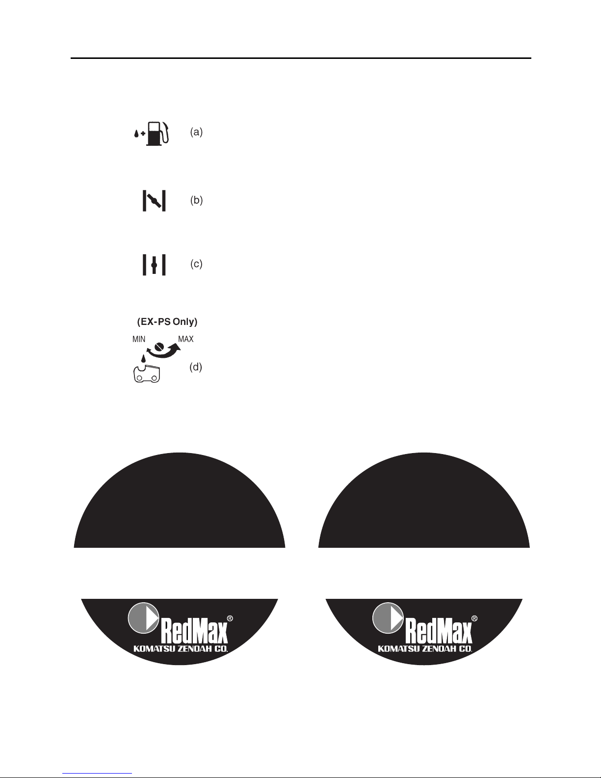
Fuel ······················································································· Mixture(Gasoline 50 : Oil 1)
Carburetor ··················································································· Walbro Diaphragm type
Spark plug·····································································································NGK CMR7A
Fuel tank capacity·······························································································22.0 fl.oz (0.65 )
Durability period··················································································································300hrs.
■EX-BC
Overall size(LxWxH)························································ 70.5(1790)x9.8(250)x12.2(310) in(mm)
Dry weight w/o acc.······························································································· 11.7 lbs (5.3kg)
Transmission··········································································· Centrifugal clutch, Rigid driveshaft
Reduction ratio ····················································································································· 1.357
Cutting head rotating direction ················································ Counter-clockwise(Operator view)
■EX-LRT
Overall size(LxWxH)························································ 90.1(2300)x9.8(250)x12.2(310) in(mm)
Dry weight w/o acc.································································································ 13.4 lbs(6.1kg)
Transmission··········································································· Centrifugal clutch, Rigid driveshaft
Reduction ratio ························································································································· 4.0
Cutting head Type···········································································Reciprocating Double blade
Tooth··········································································································28teeth
Pitch ···················································································································30
Effective cut width ··············································································16 in (40cm)
Angle adjust range ··················90°(±45° from cutting head position aligned shaft)
■EX-PS
Overall size(LxWxH)························································ 83.9(2100)x9.8(250)x12.2(310) in(mm)
Dry weight w/o bar and chain ············································································ 11.1 lbs (5.05 kg)
Transmission··········································································· Centrifugal clutch, Rigid driveshaft
Reduction ratio ······················································································································· 0.94
Cutting head Guide bar : Type······································· OREGON DOUBLE GUARD 109666
:Size ·········································································· 12(300) in(mm)
Saw chain : Type ································································· OREGON 90SG44X
:pitch x guage ······································ 3/8x0.042(9.53x1.07) in(mm)
Sprocket············································································································ 7T
Oil pump ··························································································· Plunger type
■EX-HE
Overall size(LxWxH)······················································ 72.4(1810)x18.1(450)x15.1(377) in(mm)
Dry weight w/o acc.······························································································· 14.5 lbs (7.2kg)
Transmission ············································
Centrifugal clutch, Rigid driveshaft, Bevel gears(Angle:90 deg.)
Reduction ratio·········································································································· 2.538(33.13)
Blade length······································································································· 7.87(200) in(mm)
Specifications are subject to change without notice.
5

6
(1) Read owner's manual before operating this machine.
(2) Wear head, eye and ear protection.
(3) Warning/Attention
(4) Keep all children, bystanders and helpers 15 meters away from the machine.
If warning label peel off or become soiled and impossible to read, you should contact the dealer
from which you purchased the product to order new labels and affix them in the required
location(s).
Never modify your machine.
We won't warrant the machine, if you use the remodeled brushcutter or you don't observe
the proper usage written in the manual.
WARNING
IMPORTANT
3. Warning labels on the machine

For safe operation and maintenance, symbols are
carved in relief on the machine. According to these
indications, please be careful not to make a
mistake.
(a) The port to refuel the "MIX GASOLINE"
Position: FUEL TANK CAP
(b) The direction to close the choke
Position: AIR CLEANER COVER
(c) The direction to open the choke
Position: AIR CLEANER COVER
(d) If you turn the rod by screwdriver follow the
arrow to the “MAX” position, the chain oil flow
more, and if you turn to the “MIN” position, less.
Position: Bottom of the GEAR CASE
4. Symbols on the machine
IMPORTANT
ENGINE INFORMATION
THIS ENGINE MEETS U.S. EPA PH2
AND 2001 CALIFORNIA EMISSION
REGULATIONS FOR SI SORE’s
COMPLIANCE PERIOD : CATEGORYA:
ENGINE FAMILY : 1KZXS.0254QR ; EM
ENGINE DISPLACEMENT : 25.4cc
REFER TO OWNER’S MANUAL FOR MAINTE-
NANCE SPECIFICATIONS AND ADJUSTMENTS.
Ce moteur est conformc aux normcs U.S.
EPA PH2 et 2001 ainsi qu’aux autres dispositions
ultérieures de la réglementation concernant la pollution
de l’air pour les petits moteurs tout-terrain avec une
période de accordable : CATEGORYA.
Type de moteur : 1KZXS.0254QR :EM
Cylindrée du moteur : 25,4cc
Se référer au Manuel de l’utilisateur pour les
spécifications d’entretien et les réglages.
INFORMATION IMPORTANTE
CONCERNANT LE MOTEUR
7

8
5. For safe operation
1. Read this manual carefully until you
completely understand and follow all safety
and operating instructions.
2. Keep this manual handy so that you may refer
to it later whenever any questions arise. Also
note, if you have any questions which cannot
be answered herein, contact the dealer from
whom you purchased the product.
3. Always be sure to include this manual when
selling, lending, or otherwise transferring the
ownership of this product.
4. Never allow children or anyone unable to fully
understand the directions given in the manual
to use the machine.
■WORKING CONDITION
1. When using the product, you should wear proper
clothing and protective equipment.
(1) Helmet
(2) Ear protectors
(3) Protection goggles or face protector
(4) Thick work gloves
(5) Non-slip-sole work boots
2. And you should carry with you.
(1) Attached tools
(2) Properly reserved fuel
(3) Spare blade
(4) Things to notify your working area (rope,
warning signs)
(5) Whistle (for collaboration or emergency)
(6) Hatchet or saw (for removal of obstacles)
3. Do not wear loose clothing, jewelry, short
trousers, sandals, or go barefoot. Do not wear
anything which might be caught by a moving
part of the unit. Secure hair so it is above
shoulder length.
■WORKING CIRCUMSTANCE
1. Never start the engine inside a closed room or
building. Exhaust gases contain dangerous
carbon monoxide.
2. Never use the product,
a. when the ground is slippery or when you can’t
maintain a steady posture.

b. At night, at times of heavy fog, or at any other
times when your field of vision might be
limited and it would be difficult to gain a clear
view of the working area.
c. During rain storms, during lightning storms, at
times of strong or gale-force winds, or at any
other times when weather conditions might
make it unsafe to use the product.
■WORKING PLAN
1. You should never use the product when under
the influence of alcohol, when suffering from
exhaustion or lack of sleep, when suffering from
drowsiness as a result of having taken cold
medicine or at any other time when a possibility
exists that your judgment might be impaired or
that you might not be able to operate the product
properly and in a safe manner.
2. When planning your work schedule, allow plenty
of time to rest. Limit the amount of time over
which the product is to be used continuously to
somewhere around 30~40 minutes per session,
and take 10~20 minutes of rest between work
sessions. Also try to keep the total amount of
work performed in a single day under 2 hours or
less.
1. If you don’t observe the working time, or
working manner (See ■USING THE
PRODUCT), Repetitive Stress Injury(RSI)
could occur.
If you feel discomfort, redness and swelling
of your fingers or any other part of your
body, see a doctor before getting worse.
2. To avoid noise complaints, in general,
operate product between 8a.m. and 5p.m. on
weekdays and 9a.m. to 5p.m. weekends.
Check and follow the local regulations as to sound
level and hours of operations for the product.
NOTE
WARNING
5. For safe operation
9

10
■BEFORE STARTING THE ENGINE
1. The area within a perimeter of 50 feet (15m) of
the person using the product should be
considered a hazardous area into which no one
should enter. If necessary yellow warning rope,
warning signs should be placed around the
perimeter of the area. When work is to be
performed simultaneously by two or more
persons, care should also be taken to constantly
look around or otherwise check for the presence
and locations of other people working so as to
maintain a distance between each person
sufficient to ensure safety.
2. Check the condition of working area to avoid any
accident by hitting hidden obstacles such as
stumps, stones, cans, or broken grass.
Remove any obstacle before beginning work.
3. Inspect the entire unit for loose fasteners and
fuel leakage. Make sure that the cutting
attachment is properly installed and securely
fastened.
4. Be sure the debris guard is firmly attached in
place.
5. Always use the shoulder strap. Adjust the strap
for comfort before starting the engine. The strap
should be adjusted so the left hand can
comfortably hold the handlebar grip
approximately waist high.
■STARTING THE ENGINE
1. Keep bystanders and animals at least 50feet
(15m) away from the operating point. If you are
approached, immediately stop the engine.
2. The product is equipped with a centrifugal clutch
mechanism, so the cutting attachment begins to
rotate as soon as the engine is started by putting
the throttle into the start position. When starting
the engine, place the product onto the ground in
a flat clear area and hold it firmly in place so as
to ensure that neither the cutting part nor the
throttle come into contact with any obstacle
when the engine starts.
IMPORTANT
5. For safe operation

Never place the throttle into the high speed
position when starting the engine.
3. After starting the engine, check to make sure
that the cutting attachment stops rotating when
the throttle is moved fully back to its original
position. If it continues to rotate even after the
throttle has been moved fully back, turn off the
engine and take the unit to your authorized Red
Max servicing dealer for repair.
■USING THE PRODUCT
Cut only materials recommended by the
manufacturer. And use only for tasks explained
in the manual.
1. Grip the handles firmly with both hands using
your whole hand. Place your feet slightly apart
(slightly further apart than the width of your
shoulders) so that your weight is distributed
evenly across both legs, and always be sure to
maintain a steady, even posture while working.
2. Keep cutting attachment below waist level.
3. Maintain the speed of the engine at the level
required to perform cutting work, and never raise
the speed of the engine above the level
necessary.
4. If the unit start to shake or vibrate, turn off the
engine and check the whole unit. Do not use it
until the trouble has been properly corrected.
5. Keep all parts of your body away from rotating
cutting attachment and hot surfaces.
6. Never touch the muffler, spark plug, or other
metallic parts of the engine while the engine is in
operation or immediately after shutting down the
engine. Doing so could result in serious burns or
electrical shock.
IMPORTANT
WARNING
5. For safe operation
11

12
•IF SOMEONE COMES
1. Guard against hazardous situations at all times.
Warn adults to keep pets and children away
from the area. Be careful if you are approached.
Injury may result from flying debris.
2. If someone calls out or otherwise interrupts you
while working, always be sure to turn off the
engine before turning around.
■MAINTENANCE
1. In order to maintain your product in proper
working order, perform the maintenance and
checking operations described in the manual at
regular intervals.
2. Always be sure to turn off the engine before
performing any maintenance or checking
procedures.
The metallic parts reach high temperatures
immediately after stopping the engine.
3. When replacing the cutting attachment or any
other part, or when replacing the oil or any
lubricant, always be sure to use only RedMax
products or products which have been
certified by RedMax for use with the RedMax
product.
4. In the event that any part must be replaced or
any maintenance or repair work not described in
this manual must be performed, please contact a
representative from the store nearest RedMax
authorized servicing dealer for assistance.
5. Do not use any accessory or attachment other
than those bearing the RedMax mark and
recommended for the unit.
6. Under no circumstances should you ever take
apart the product or alter it in any way. Doing so
might result in the product becoming damaged
during operation or the product becoming unable
to operate properly.
■HANDLING FUEL
1. The engine of the RedMax product is designed
to run on a mixed fuel which contains highly
flammable gasoline. Never store cans of fuel or
WARNING
5. For safe operation

5. For safe operation
refill the tank of the unit in any place where there
is a boiler, stove, wood fire, electrical sparks,
welding sparks, or any other source of heat or
fire which might ignite the fuel.
2. Never smoke while operating the unit or refilling
its fuel tank.
3. When refilling the tank, always turn off the
engine and allow it to cool down. Take a careful
look around to make sure that there are no
sparks or open flames anywhere nearby before
refueling.
4. Wipe spilled fuel completely using a dry rag if
any fuel spillage occurs during refueling.
5. After refueling, screw the fuel cap back tightly
onto the fuel tank and then carry the unit to a
spot 10 feet or more away from where it was
refueled before turning on the engine.
■TRANSPORTATION
1. When hand-carrying the product, cover over the
cutting part if necessary, lift up the product and
carry it paying attention to the blade.
2. Never transport the product over rough roads
over long distances by vehicle without removing
all fuel from the fuel tank. If doing so, fuel might
leak from the tank during transport.
13

14
■MOUNTING ENGINE (SE1)
1. Push the driveshaft housing toward the clutch
housing and rotate it by hand to check that the
driveshaft is engaged with the gears.
2. Insert the driveshaft housing into the clutch
housing until it bottoms, and align the positioning
holes on the clutch housing and the shaft tube
and install the screw. When difficult to engage,
twist the engine slightly.
3. Fasten the clamp securely with two screws.
Tighten the screws gradually by turns.
■CONNECTING THROTTLE WIRE
1. Remove the air cleaner cover.
2. Connect the end of the throttle wire to the joint
on the top of the carburetor. (SE2)
■CONNECTING SWITCH WIRES
•Connect the switch wires between the engine
and the main unit. Pair the wires of the same
color.
■INSTALLING HANDLE
(EX-BC, EX-LRT only) (SE3)
•Install the handle to the shaft tube and clamp it
at a location that is comfortable to you.
(1) About 19 inches (48cm)
(EX-PS only) (SE4)
•Insert the grip to the shaft tube.
•Fasten the clamps with screws.
(EX-HE only) (SE5)
•Install the J-shaped handle to the shaft tube and
clamp at a position best for your job.
■JOINT ATTACHMENT (SE6)
•Insert the attachment to the main shaft.
•Tighten the knob bolt securely.
(1) Knob bolt
IMPORTANT
6. Set up
SE1
SE2
(1)
SE3
SE5
(1)
SE6
SE4

6. Set up (EX-BC only)
EX-BC
SE2
■INSTALLING DEBRIS GUARD
•Put the debris guard on the gear box, attach it
with the 4 screws and hardware provided. (SE1)
(1) debris guard
(2) plate
(3) screw
■INSTALLING CUTTING HEAD (SE2)
1. While locking the gear shaft, by inserting the
supplied tool into the upper holder on the gear
box, loosen and remove the hexagon nut(left-
handed)
2. Then screw in the cutting head to the gear shaft
over the holders. Hand-tighten it securely.
■BALANCE UNIT
1. Put on strap and attach unit to strap.
2. Slide clamp up or down until unit balances with
head just touching on the ground. (SE3)
EX-BC
SE3
(1)
(2)
(3)
EX-BC
SE1
15

6. Set up (EX-LRT only)
EX-LRT
SE1
■
ATTACHING THE TRIMMING MECHANISM (SE1)
1. Remove the screw screwed into the end of the
trimming mechanism.
2. Insert the end of the trimming mechanism into
the main pipe.
3. Line up the hole on the end of the trimming
mechanism into which the screw is to be
inserted with the hole on the main pipe, and
screw the screw firmly in.
4. Using a wrench, screw in the bolt provided to fix
the trimming mechanism into place.
(1) Main pipe
(2) Trimming mechanism
(3) Screw hole
(4) Screw
(5) Fastening bolt
■BALANCE UNIT
1. Put on strap and attach unit to strap.
2. Depending on the working posture, slide clamp
up or down until unit balances and the strap fits
your body.
16

6. Set up (EX-PS only)
(1)
(2)
(3) (4)
(5)
EX-PS
SE1
EX-PS
SE2
EX-PS
SE3
■
ATTACHING THE PRUNING MECHANISM (SE1)
1. Remove the cap on the end of the main pipe.
2. Remove the screw screwed into the end of the
gear case.
3. Insert the end of the gear case into the main
pipe.
4. Line up the hole on the end of the gear case into
which the screw is to be inserted with the hole
on the main pipe, and screw the screw firmly in.
5. Using a wrench, screw in the bolt provided to fix
the mechanism into place.
(1) Main pipe
(2) Gear case
(3) Screw hole
(4) Fastening bolt
(5) Bolt
A standard package contains the items as shown
below. (SE2)
(1) Guide bar
(2) Saw chain
(3) Gase case
(4) Sprocket
(5) Chain tension adjust screw
(6) Nut
(7) Chain tensioner nut
(8) Chain cover
Install the guide bar and the saw chain on the gear
case as follows.
The saw chain has very sharp edges. Use
protective gloves for safety.
1. Loosen a nut and remove the chain cover.
2. Mount the guide bar then fit the saw chain
around the bar and sprocket. (SE3)
Pay attention to the correct direction of the saw
chain
WARNING
WARNING
17

6. Set up (EX-PS only)
3. Fit the chain tensioner nut into the lower hole of
the guide bar, then install the chain cover, and
fasten the mounting nut to finger tightness.
(SE3)(SE4)
(1) Hole
(2) Moving direction
(3) Chain tensioner nut
4. Adjust the chain tension by turning the tensioner
screw until the tie straps just touch the bottom
side of the bar rail. (SE5)
(1) Chain tension adjusting screw
(a) Loosen
(b) Tighten
5. Tighten the mounting nut securely with the bar
tip held up (SE6)(TORQUE: 8.9~11.7
N.m./90~120 kg-cm). Then check the chain for
smooth rotation and correct tension while
moving it by hand. If necessary, readjustment.
(1) Tighten
It is very important to maintain the proper chain
tension. Rapid wear of the guide bar or the
chain coming off easily can be caused by
improper tension. Especially when using a new
chain, take good care of it since it should
expand when first used.
■BALANCE UNIT
1. Put on strap and attach unit to strap.
2. Depending on the working posture, slide clamp
up or down until unit balances and the strap fits
your body.
WARNING
EX-PS
SE4
EX-PS
SE5
EX-PS
SE6
18

6. Set up (EX-HE only)
EX-HE
SE1
EX-HE
SE2
EX-HE
SE3
EX-HE
SE4
1. Insert the driveshaft into the clutch drum, then
attach the gearbox to the shaft tube as aligning
the positioning holes. Wipe out grease on the
tube and the inside of the gearbox. Screw in the
lock screw and fasten the clamp bolt firmly.
(SE1)
(1) Clamp bolt
(2) Lock screw
2.Install the blade guard to the gear case with the
provided 3 screws, then clamp it to the shaft
tube with 2 screws. (SE2)
3.Place the blade between the cutter holders (A)
and (B) while locking the gear shaft by putting
the bar, one of the tools provided, through the
key holes on the holder(A) and the gearcase.
Use the socket and the screwdriver as shown in
the picture below to tighten the blade mounting
bolt. (SE3)
(1) Blade mounting bolt (Left-handed)
(2) Cutter holder (B)
(3) Blade
(4) Bar
(5) Cutter holder (A)
4.Split the bracket and install the wheel assembly
to the shaft tube and clamp at a position best for
your job. (SE4)
(1) Bracket
19

20
•Gasoline is very flammable. Avoid smoking
or bringing any flame or sparks near fuel.
Make sure to stop the engine and allow it
cool before refueling the unit. Select outdoor
bare ground for fueling and move at least
3m(10ft) away from the fueling point before
starting the engine.
•The RedMax engines are lubricated by oil
specially formulated for air-cooled 2-cycle
gasoline engine use. If RedMax oil is not
available, use an anti-oxidant added quality oil
expressly labeled for air-cooled 2-cycle engine
use. (JASO FC GRADE OIL or ISO EGC
GRADE)
RECOMMENDED MIXING RATIO
GASOLINE 50:OIL 1
•Exhaust emission are controlled by the
fundamental engine parameters and
components(eq., carburation, ignition timing
and port timing) without addition of any
major hardware or the introduction of an
inert material during combustion.
•These engines are certified to operate on
unleaded gasoline.
•Make sure to use gasoline with a minimum
octane number of 90 ROZ(USA/Canada : pump
octane min.87)
•Unleaded gasoline is recommended to reduce
the contamination of the air for the sake of your
health and the environment.
•Poor quality gasolines or oils may damage
sealing rings, fuel lines or fuel tank of the
engine.
■HOW TO MIX FUEL
1. Measure out the quantities of gasoline and oil to
be mixed.
2. Put some of the gasoline into a clean, approved
fuel container.
3. Pour in all of the oil and agitate well.
4. Pour in the rest of gasoline and agitate again for
at least one minute.
5. Put a clear indication on the outside of the
WARNING
50:1 MIXING CHART
GASOLINE gal. 1 2 3 4 5
2-CYCLE OIL fl.oz 2.6 5.2 7.8 10.4 13
GASOLINE liter 1 2 3 4 5
2-CYCLE OIL ml 20 40 60 80 100
7. Fuel
Table of contents
Other RedMax Lawn And Garden Equipment manuals

RedMax
RedMax EXtreme EX-LRT Owner's manual

RedMax
RedMax GK-280 Owner's manual

RedMax
RedMax BCZ2500S/SU Owner's manual

RedMax
RedMax LRT-A Owner's manual

RedMax
RedMax GK-280 Owner's manual

RedMax
RedMax AG4300 Owner's manual

RedMax
RedMax EXTREME EXZ2460S-PH Owner's manual

RedMax
RedMax SGCZ2500S Owner's manual

RedMax
RedMax SGC2300DL Owner's manual

RedMax
RedMax SRTZ235 User manual
Popular Lawn And Garden Equipment manuals by other brands

Im-en Export Frijters Rijsbergen B.V
Im-en Export Frijters Rijsbergen B.V LaserOP 3.0 instruction manual

SMART
SMART 20623R01 instruction manual

Craftsman
Craftsman 316.792440 Operator's manual

Palram
Palram 700492 Assembly instructions

Gardigo
Gardigo BIRD-SCARER Kite manual

Gronomics
Gronomics PB 18-48 Assembly instruction