Redpath Tunnelhouse Mk2 User manual

Effective from 31-Oct-23 Page | 1
Watch the Redpath Greenhouses YouTube channel for Mk2 Tunnelhouse assembly videos
Tools & parts suggested: Step ladder, Saw-stools, Hammer, Rubber Mallet, Secateurs, Scissors, Tape measure, Cordless drill,
Level, String-line, Marker pen, Safety gear (as needed). Pegs and Screws to secure the base, or timber base materials.
See the suggested peg locations below to secure the alloy base.
See B1 on page 2, & graph on page 3 for the internal size measurements of your base to match the supplied alloy base.
Check the base is level. Use long screws or coach-bolts to secure the alloy base to your timber base.
Please use suitable foundation pegs for your wind exposure and soil conditions, see image GP1 GP2 page 2
Redpath Pacific Ltd
PO Box 9058
16 Bounty Place
Palmerston North 4414
Free Ph. 0508-733-728
Email [email protected]
www.redpath.co.nz

Effective from 31-Oct-23 Page | 2
If you are adding a timber base frame:
The tunnelhouse includes alloy base rails, however if your ground is undulating you may wish to build your own additional base from
100mm x 50mm or 150mm x 50mm timber etc.
(GP1) 600mm Ground peg connection to alloy base rail. (GP2) Place a ground peg 400mm from corner on side base rail x 4
2 x options shown below with or without timber base rail Two at each end beside studs, & every 1.5m max along sides.
B1 - INTERNAL MEASUREMENTS –if adding your own timber base
Internal measurements for all sizes:
3m A = 2.3m, B = 3032mm, C = 3805mm
10.5m A = 2.3m, B = 10532mm, C = 10780mm
4.5m A = 2.3m, B + 4532mm C = 5082mm
12m A = 2.3m, B = 12032mm, C = 12250mm
6m A = 2.3m, B = 6032mm, C = 6456mm
15m A = 2.3m, B = 15032mm, C = 15207mm
7.5m A = 2.3m, B = 7532mm, C = 7875mm
18m A = 2.3m, B = 18032mm, C = 18178mm
9m A = 2.3m, B = 9032mm, C = 9320mm
21m A = 2.3m, B = 21032mm, C = 21157mm
24m A = 2.3m, B = 24032mm, C = 24142mm

Effective from 31-Oct-23 Page | 3
Step 1: Join together the side base rails:
Assemble each side base rail use 2 x 16mm screws supplied in the order and the lengths shown in the chart below.
Helpful Hint: For example if the building is facing north to south, assemble the side base rails so that the 1st 3587mm rail on the
west side begins at the “south end” and the 1st 3587mm rail on the east side begins at the “north end”.
See the side base rail assembly video on our YouTube channel
10.5m
Join 3587mm +3m +4m
3m
Uses 1 rail 3087mm no join
12m
Join 3587mm +3m +3m +2.5m
4.5m
Join 3587mm & a 1m
15m
Join 3587mm +3m +3m +3m +2.5m
6m
Join 3587mm & a 2.5m
18m
Join 3587 +3m +3m +3m +3m +2.5m
7.5m
Join 3587mm & a 4m
21m
Join 3587mm +3m +3m +3m +3m +3m +2.5m
9m
Join 3587mm +3m +2.5m
24m
Join 3587mm +3m +3m +3m +3m +3m +3m +2.5m
Join the side base rails so that you have two equal length rails & have the internal hoop saddles opposite each other.
The Duralock groove faces to the outside and along the top edge of each of the side rails See image BR2 page 5
The pre-fitted steel saddles face to the inside and should be at 1.5m spacing if the rails are in the correct order of assembly.
Use two 16mm screws to connect the rails together. See image within BR1 below
Step 2: Stand up the pre-made door end and back walls, secure them to side base rails with 3 screws. The side base rails
finish flush at their ends with the outside face of the end wall base rail (See Pic BR3 and You tube video of wall assembly)
* Stand up the rear wall - the Duralock groove for the rear wall faces to the outside. Check the wall is vertical and use three screws
to connect the end of the side base rail to the rear wall base rail see Images BR1 & BR2 & BR4 below and Page 4
* Stand up the front wall –The door guide faces to the outside
Check the wall is vertical and use three screws to connect the end of the side base rail to the rear wall base rail see Images BR1
& BR2 & BR4 below and Page 4
Note, the door end
base rail has the door
guide facing to the
OUTSIDE,
BR1 - Sleeve the side base rails togther and stand up and attach the front and rear walls, See the side base rail
assembly and standing up end walls video on our YouTube channel

Effective from 31-Oct-23 Page | 4
BR2 Corner Gussets
BR3 -The end wall finishes flush with the side base rails BR4 - Internal corner brackets with screws fitted
Step 3: Slide the internal hoop(s) into the side base rail saddles
NOTE 1: *If there is a roof vent on your building –the two hoops that are located at each end of the roof vent should be positioned so
that their smooth side face, - faces toward each other.
NOTE 2: We suggest not securing the internal hoops with the two screw(s) at their base saddles until after the covering has been
fitted. This allows the hoops to be lifted ‘upwards’ after the covering is in place to help with tensioning the cover.
*For the 15m, 18m 21m & 24m models fit the horizontal collar tie to each central hoop. See image CT1 Page 7.
Door End base rail,
Duralock groove
faces to INSIDE
Side base, groove to
OUTSIDE
The rear wall and side base rails have the
Duralock groove facing to the OUTSIDE
The side base rail
finishes flush with the
front face of the end
base rails.
Internal hoops placed in position into side base rail saddles

Effective from 31-Oct-23 Page | 5
SAD1 (Internal hoop saddle + screws after the cover installed)
Step 4: If you have a roof vent option install the roof vent base part now, See the YouTube video “Roof vent part 1, vent base”
See Image V1 below.
NOTE: The roof vent may be positioned in any of the Tunnelhouse 1.5m sections; however, you cannot fit a roof vent in a section directly
beside another section that might already have a roof vent. The two hoops that will have the roof vent fitted in-between them should have their
flat aluminium side faces, - facing toward each other.
When you have decided which section to place the roof vent in, double-check that the hoops are 1.5m at the apex apart then ….
1. Use two 22mm screws at the end of each vent rail to secure the rails to the top face of the central hoops (8 screws in total)
V1 If you have a roof vent option, Fit the roof vent steel base rails now –Use 2 x 25mm screws at each end (8 in total)
Step 5a: Join the 4 roof purlins –See YouTube video “Mk2 Purlin assembly”
Step 5b: Fit the 4 roof purlins. See YouTube video “Mk 2 purlins being installed”
* Sleeve together the four 25 x 25mm aluminium lengthways purlins using each length only in order as shown in the below table for your
tunnelhouse size. When joining the purlins keep the white Polyguard tape on the same side for their full length (this will face to the
outside when installed) See image PR1 page 6
Use 2 x 16mm screws to join the purlins - do not screw through the white Polyguard face!
* The end hoop saddles are already pre-fitted for you. Stretch a string line end-to-end between the end saddles and mark the central
hoops with a pencil to find the position of where the internal saddles/purlins will sit.
* Use the saddles and the 16mm screws supplied to attach the purlins to the underside of your central hoops. See image P2
page 6.
* Wrap a small piece of Polyguard around the ends of each purlin to help protect the end wall covering, See image P3 page 6
* If you have a 15m or longer tunnel, or have an X wind kit option you can fit the collar tie braces See image CT1 page 7

Effective from 31-Oct-23 Page | 6
Sleeve (J) includes the joiner sleeve see Redpath purlin assembly video on Redpath YouTube
10.5m
Join 766mm(J) + 3mJ + 3mJ + 3mJ + 766mm
3m
Uses 1 Piece @ 3032mm
12m
Join 766mm(J) + 3mJ +3mJ +3mJ + 2266mm
4.5m
Join766mm(J) & a 3mJ & a 766mm
15m
Join 766mm(J) + 3mJ + 3mJ +3mJ +3mJ + 2266mm
6m
Join 766mm(J) & 3mJ & a 2266mm
18m
Join 766mm (J) + 3mJ +3mJ +3mJ +3mJ +3mJ + 2266mm
7.5m
Join 766mm(J) & a 3mJ & a 3mJ +
766mm
21m
Join 766mm(J) +3mJ+3mJ+3mJ+3mJ+3mJ+3mJ+ 2266mm
9m
Join 766mm(J) & a 3mJ & a 3mJ +
2266mm
24m
Join 766mm(J) + 3mJ+3mJ+3mJ+3mJ+3mJ+3mJ+3mJ +
2266mm
(P1) Slide purlins into the pre-fitted end saddles. Polyguard (P2) Three screws are used to secure the saddle for the central
face goes to the outside, use 1 x 16mm screw to secure. Hoop purlins
Wrap a small piece of Polyguard around the end of purlin
Four purlins shown in red, thieir position is dictated by the pre-fitted end hoop saddles, Fit the saddles supplied to secure the purlins to the
underside of the center hoops See the purlin assembly & installation video on our YouTube channel
4 x End saddles already
pre-fitted
Image PR1

Effective from 31-Oct-23 Page | 7
Step 6: Side wall angle braces: See YouTube video “Mk2 side wall braces x 4”
Position the side wall angle bracing with the Polyguard tape surface facing to the outside as shown below image WB1 & WB2.
Place the angle brace into approximate position, Fasten the lower end to the inside face of the base rail with one 16mm screw. Fasten
the top end of the brace to the inside face of the end hoop using one 16mm screw.
The top end of the brace should not protrude outside the end hoop otherwise it may damage the end wall covering when it is fitted.
Note: Side wall angle brace may require re-positioning or shortening if you have chosen an optional shelf. The shelf height chosen may
interfere with the wall brace.
Some models and high wind-kit models will have extra sidewall braces included. Please fit all supplied sidewall / end-wall braces
W1 Fit sidewall braces
Wind upgrade kit collar tie option below (included with 15m and over models or as an optional extra on shorter models)
See our YouTube channel for video “Mk2 high wind kit parts install”
The “X”wind kit consists of three main parts.
(1) Collar ties that fit to each central arch hoop, see image below
(2) Extra sidewall 1.5m angle braces.
(3) End wall angle braces 1.2m (use same method as sidewall braces to fit)
Note: Already fitted at the factory is a hoop strengthening foot inside the ends of the central hoops
IMAGE CT1 - Fit 1 x Collar tie to all central hoops, Locate horizontal in center as shown below. Use 3 x16mm screws each side (see
video)

Effective from 31-Oct-23 Page | 8
Step 7. The Clipping systems to secure the covers. View Redpath YouTube videos of the two commercial greenhouse film clipping
systems used on this Tunnelhouse design ( V Lock and Duralock)
1) This design uses two types of cover clipping systems (V Lock and Duralock)
Type 1: One piece V Lock clipping system - used on end hoops only
Lockstrip V Lock - is a white colored, V Shaped 60mm length UPVC, and is used on the end hoops and 4 pieces are used at the apex of
the internal hoops where the roof vent ends.
IMPORTANT The insert and the clip parts must be positioned in the direction shown, See drawing below V Lock shown in Red. (the
vertical face always faces toward the cover being held)
(1) The sequence below shows the V clip assembly. See our You-Tube channel for install video.
Whilst pulling the cover tight, position the insert as shown below, Roll the V clip inserts into position into the groves.
Position the 60mm V lock bead (shown in red below) into the end hoop profile. DO NOT FIT BACKWARDS! (common error)
Angle the front of the clip, squeeze it closed slightly, push the front edge under the aluminium groove and roll the rear of the clip down
into the groove to trap the covering (shown in blue below) leave a space approximately 10 mm between the pieces
CHECK: When installed the vertical face of the V lock will face toward the covering being held!
Image L4 - Use the 60mm V lock inserts in the front & also the top face of
the curved part at each end hoops. Space the V lock inserts approximately 10mm apart –See Redpath YouTube videos.
Note: A piece of V lock is removed when positioning the door track
The 60mm “V” Lock inserts, are spaced at approximatley 10mm gap between them.

Effective from 31-Oct-23 Page | 9
Type No2: Duralock 2 piece clipping system
The Duralock groove inserts are made up of 1.5m white ‘channel shaped’ inserts and a rectangular white ‘bead’ insert. These are
inserted into the Duralock aluminium grooves used on base rails, door, and end studs / lintels.
How to assemble Duralock –see below or see YouTube videos of Duralock 2 assembly
1. Pull the cover and tension it over the jaw of aluminium.
2. Face the channel strip as shown below and Insert it by tilting it slightly and pressing it down and into the groove WHILST you
releasing the tension from the tail of the film. ‘Seat’ the channel into the alloy groove. Use secateurs to trim the Duralock parts to
length.
3. Tap the rectangular locking bead into place with the rounded edge facing down as shown
Sequence used to install Duralock clipping strips. Fit channel first then locking bead afterwards. ONLY place in direction shown
IMPORTANT!
(A) Locking Lug Forward (B)Tilt Channel Insert (C) Fully Seat Channel Insert, then fit Bead
Below picture shows all parts of Duralock assembled End view of the base rail below
FITTING COVERS TO THE TUNNELHOUSE
The covering is supplied in separate pieces. 1 for the door(s), 1 for each end, and 1 for the roof/side.
Install the covers on a warm, calm day.
When trimming off the covers leave a 100mm ‘tail’ in place initially and when satisfied with the tension on the various parts , you can
trim the tail to within 20mm for a tidy appearance
1. DOOR COVER –Use the Duralock channel and bead. See YouTube video “Mk2 door covering install”
Lay the door frame on the ground with Duralock groove facing upward and lay the 2m x 1m door cover in approximate position
You will need to cut the clipping inserts (channel and bead) with a pair of secateurs to suit the length of the frame work grooves. The
clipping inserts should be cut to length finish approximately 25mm short of each corner.
You will begin by fitting the clipping insert to the top door rail firstly, - then the bottom door rail (pulling the cover tight as you do so).
Then install the inserts into the side door edges. (begin in the middle and work toward the corners)
Bead
Channel
Alloy
channel

Effective from 31-Oct-23 Page | 10
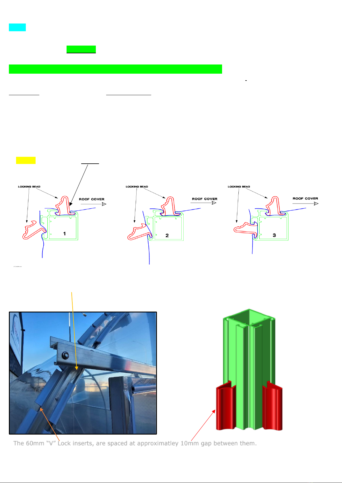
2. ROOF COVER, use the 60mm pieces of white “V Lock” on the end hoops only, See our YouTube channel “Mk2 Roof
covering videos steps 1 to 11 ”
If your Tunnelhouse includes a roof vent install the roof vent base before fitting roof covering (See step 4 on page 5, image V1)
NOTE: Take care not to damage the covering on the ends of the vent rails, Unfold the cover and lay it out over the Tunnelhouse so
that it rests in approximate position with an equal amount of excess film draping over each end hoop and to each side base rail.
As per the YouTube videos begin at the apex at one end of the Tunnelhouse and install two pieces of 60mm V lock insert in the
direction as shown above (do not put in backwards!) , Then position a piece to your left and right where the curvature of the end stops
and the sidewall begins (9 o’clock and 3 o’clock positions)
Move to the opposite end, pull the cover tight along its length and repeat the step above.
If satisfied with the cover flatness and tension, begin to fill in the gaps in-between the inserts already fitted. If not satisfied with the
tension, un-clip the V Lock re-tension the cover and re-fit the V lock
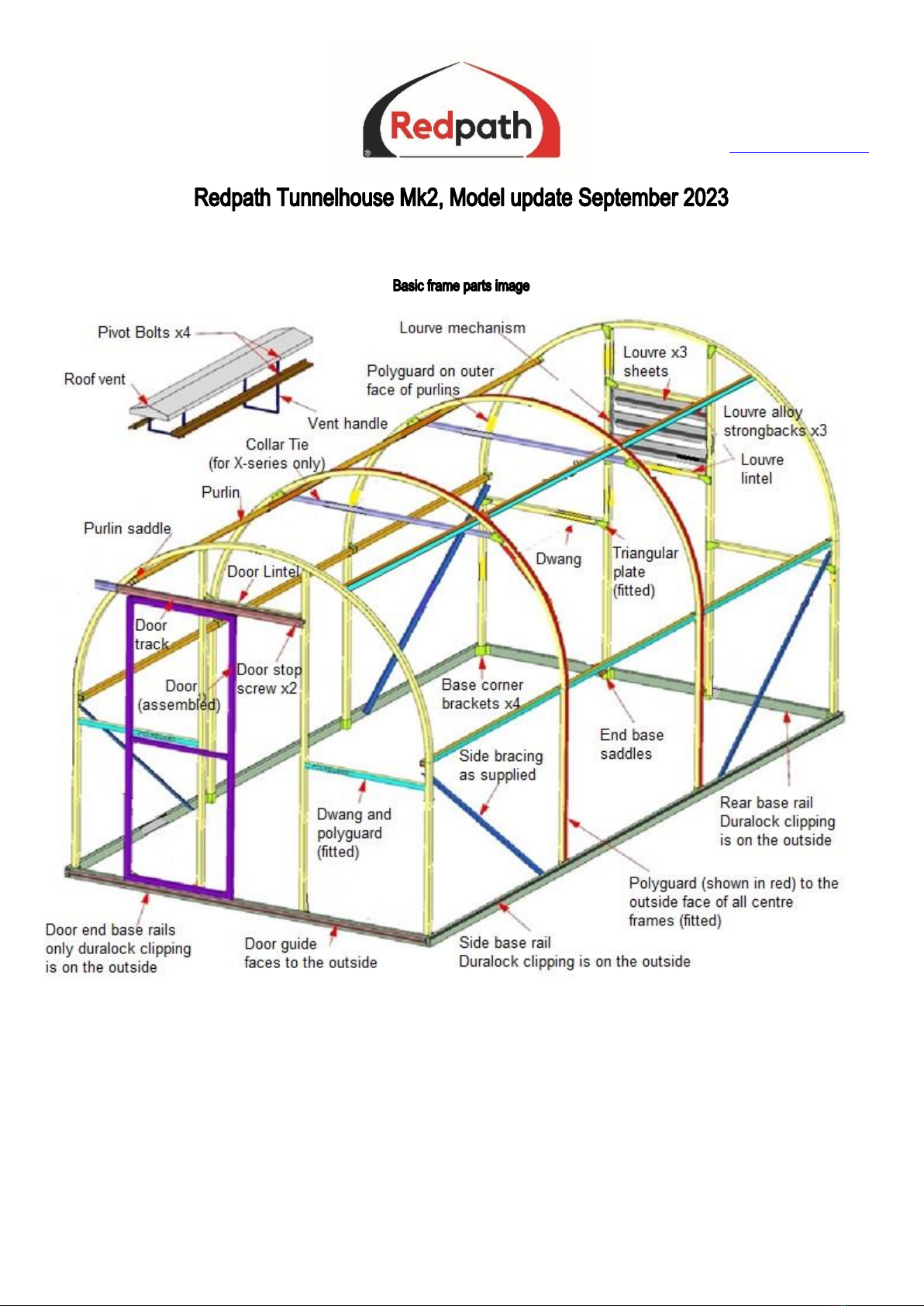
Now move to the side base rails. The side base rails use the Duralock clipping system (see assembly order page 10, and see
YouTube videos)
TIP: When fitting the side base rail clipping its sometimes simpler to lift the entire side of the Tunnelhouse up in the air and rest it on
blocks or saw stools –this can make it more convenient to insert the sidewall base rail Duralock clip.
Begin at the center of the base rail & start inserting the U shaped Duralock channel insert + bead whilst tensioning the cover as
much as possible. Work your way to the left and right toward the ends of the building. (See image on Page 10 above)
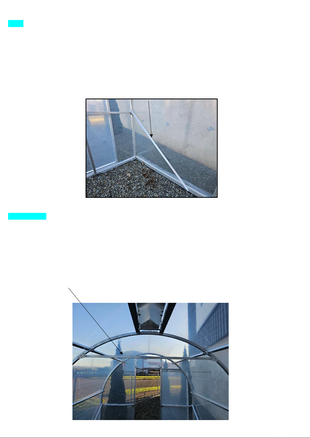
3. END WALLS:
You will fit the 3m x 3m end walls cover in one piece (see video)
Use the 60mm V shaped Lockstrip insert for the front face wall of the end hoops See image L4 page 8
Like the roof ends - Start at the apex and position a 60mm piece. Then position a piece to your left and right where the curvature of
the end stops and the sidewall begins (9 o’clock and 3 o’clock positions)
Then pull the cover flat and position another 60mm piece of Lockstrip midway in-between these two.
If satisfied with the cover flatness and tension, begin to fill in the gaps in-between these inserts and also the rest of the end wall edges
and base rail parts.
NOTE: At the door end the base rail Duralock groove is on the INSIDE of the tunnelhouse, - this is so that there is sufficient
clearance between the end wall covering and the sliding door.
Note: When you come to fitting the door track remove one or two pieces of the 60mm V Lock on the front face of the end hoop where
the door tack will be attached to the hoop, so that the track sits flush on the hoop face. See image L4 Page 8
Create the opening for the door or louvre end wall cladding. Use a knife or scissors & cut an “X” shape by cutting diagonally from corner to
corner where the door or louvre are to be positioned. You can then place the Duralock clipping around the perimeter edge of the door and
louvre openings using the Duralock clips. Stop the clip system approximately 25mm short of any corner.
Step 8: ROOF VENT CAP: If an option on your tunnelhouse.
The roof vent base has already been fitted in Step 4.
After the main roof and sidewall covering has been fitted, - you can re-fit the cap vent See our roof vent videos on YouTube
1. Create the opening for the vent in the roof cladding where the vent will be placed (between the vent base rails). Use a knife or
scissors & cut an “X” shape by cutting diagonally from corner to corner between the steel vent rails See image V4 below
2. The Duralock2 clip system is used along each of the 1.5m steel vent rail See image V2 & V4 below
3. Insert 3 pieces of the 60mm V Lock at the apex of the hoops at both ends of vent See image V2 & V4 below
4. Secure the tail of the cover on top of the steel upstand using the white Omega clips See image V2 / V4 below
5. Trim off the excess film behind the Omega clip to 25mm and also at the end of the roof vent
6. Install the roof cap using the 6mm bolts, spacers and nuts supplied See image V3 below and Youtube video.
Test the roof vent for open / close action and adjust tension on pivot bolts if needed.
For Auto opener vent option see V5 below

Effective from 31-Oct-23 Page | 11
V2 –Vent parts V3 -Use the supplied 6mm bolt, Nylock nut, + Nylon packer as
shown below to attach the cap vent to the 4 lever arms.
V4 Cut cover along center and into corners , then fit vent base
V5 Auto opener option: Position and attach the auto solar-vent opener as below
3 x 60mm V Lock insert at ends
to hold roof film at each end
Omega clip x 5
each side of top edge of
steel vent rail to hold tail
of film
3 x 60mm V lock
inserts here
Use Duralock
Insert along here
1.5m
Use 5 x Omega
clip here
Use Duralock
Insert along here
1.5m both sides

Effective from 31-Oct-23 Page | 12
Step 9. Fitting the louvre window (rear or sidewall option)
After the tunnel has had its covers fitted - slide the three polycarbonate sheets into place. Remove the backing tape from the 570mm
aluminium strong-back angles and adhere one across the center of each blade to stiffen them. See rear wall louvre video YouTube
Step 10. Door
Note: Do not fit the door track or the door itself to the building until after the door end wall covering has been fitted.
Fitting the door and door track See YouTube for door and door-track install videos
1. Rest the door on top of the end base rail and slide the door track onto the two door rollers
2. The base door guide slot is pre-fitted to the front face of the base rail and the slider fin is already fitted the underside of the door. See
image D2 below
3. Lift up the door track with door attached into approximate position so that the weight of the door is suspended on the track, and the
fin on the underside of the door is within the door guide slot.
4. You will need to remove one or two of the 60mm Lockstrip inserts from the front face of the arch, See image L4 Page 9 so that the
Door track screws to the front face of the tunnelhouse. Using the longer 22mm screws, - screw through the door track hanger plate
See image D1, D3, D4 below check that the track is level and then secure with another 22mm screw at opposite end.
Check the door sliding action is smooth in the track and the base guide, and add more screws along the door hanger plate
5. Place a screw through each end of the door track (See image D1 below) to act as a stop for the door rollers so that the door cannot
slide off the track at its ends.
Note: The Dual door option uses the longer type 1.8m door-track.
Pic D1 Screws mount the door track, Door roller “stop “screw. Pic D2 Door guide fin underside of door, and door fin guide slot
Remove the backing tape and stick the strong back angle alloy angle
across the center of each louvre blade to stiffen the polycarbonate.
Louvre mechanism is already pre-
fitted
Door hanger plate

Effective from 31-Oct-23 Page | 13
(Pic D3) (Pic D4)
OPTIONAL ACCESSORY “Throw-over” temporary Shadecloth cover for summertime shade:
Throw-over Shadecloth cover is an option extra for reducing internal temperatures. The shade cover is 6m wide so that it fits up-and-over
the tunnel from side-to-side. Ropes & brackets are included to help secure the cover in place.
The drawing below shows approximate retaining rope positions and saddles to be screwed to the base rail or your base timber.
Use one rope beside each hoop, and place the rope approximatley 200-300mm in from each end.
If a roof vent is fitted place the rope to the side of the vent.
Tension the rope so that it is not slack –but do not over-tension
22mm Screws across linel and
into end hoop
22mm screws to secure
door track

Effective from 31-Oct-23 Page | 14
Sidewall louvre:
You can assemble and fit the sidewall louvre option extra after the main roof cover has been installed.
Fit the 4 x aluminium parts and 8 x triangle brackets as shown below. Cut an “X” in the plastic covering where the blade mechanism is to
be fitted, and use the Duralock clip system around the perimeter of the 600mm x 600mm window area only
Fixed sidewall screen:
The sidewall fixed screen vent optional extra is for the full length of the tunnelhouse.
Fit the 30mm x 30mm x 1468mm noggins (with groove facing toward the ground) in-between the hoops approximately 350mm –600mm
above the base rail. Use the triangle brackets and screws provided to secure each end of the noggins to inside face of hoops.
Screw the twin Groove Duralock to the outside face of the noggin for the full length of the tunnelhouse and trim the end to length.
When you come to fitting the roof and side cladding, you will fit the roof sheet to the top groove of the twin groove Duralock and the lower
Shadecloth to the lower groove of the Duralock and the buildings base rail
Fixed sidewall screen option
Side or rear aluminium shelf: See rear wall shelf video on Redpath YouTube
The shelf bracket is fitted to the vertical section and side face of the arch hoops at your preferred height.
Ensure that the buildings purlins are above the position of the shelf.
The end wall angle brace may require shortening and repositioning so that it clears the end shelf bracket (depends on your choice of shelf
height)
If your shelf is longer than 3 meters, the aluminium shelf slats may have joins and sleeves. You will need to join the 25mm x 25mm shelf slat
parts with the sleeves and screws supplied to make the correct length for each shelf slat.
Fit the supplied noggins between each hoop
Screw twingroove Duralock along
the full length

Effective from 31-Oct-23 Page | 15
SHELF INSTALLATION:
There is one shelf bracket for each arch hoop including the end ones
There are four shelf brackets for an end wall shelf (1 on each stud and 1 on each end hoop
1. Position a shelf bracket at the same height at each end using three screws into the uprights, see image S1
Position a string line between the two end brackets, check that it is level and pull it tight.
2. Position the center shelf bracket(s) at the string line height
3. There are 5 aluminium 25 x 25mm shelf slats. The slats finishes flush with shelf bracket at their ends. see image S3
4. Fit the front and rear shelf slats using the screws provided and screw through the pre-drilled shelf bracket holes from the underside, see
image S2.
5. Fit the remaining three slats and space them evenly there will be an approximate 36mm gap between each slat.
S1 - Fold faces inwards S2 - Position rear and front slat S3 - Slats finish 30mm from end
Tunnel Operation + Maintenance schedule:
Close roof vents, doors and windows in windy conditions.
* Clean your greenhouse once per year to remove algae / pollen / dirt. Use dishwashing liquid and a soft broom.
* Wash down the interior of the tunnel house to prevent degradation of the covers or alloy or steel parts
* Repair with greenhouse film tape and holes,rips or tears
* Treat any steel parts such as Vent, Saddles, Plates, Door hangers etc. with rust kill once yearly or if corrosion appears.
* Check for any loose or missing screws each 12 months, Tighten or Replace as needed.
* Check foundation attachment and foundations are secure each 12 months to ensure tunnel is well held in place from wind
* Each 7-10 years replacement cover kit may be purchased online www.redpath.co.nz for all sizes of tunnel kits.
Other Redpath Greenhouse Kit manuals
Popular Greenhouse Kit manuals by other brands

Harbor Freight Tools
Harbor Freight Tools 94515 Assembly instructions

Konifera
Konifera SF2500 Assembly instructions

Palram
Palram Automatic Vent Opener Assembly instructions

Palram
Palram CANOPIA SANREMO 3x3 How to assemble

Elite Greenhouses
Elite Greenhouses TITAN K800 Instructions & Illustrations

Halls
Halls Magnum 108 manual

VOLYA
VOLYA PRIMA 4 Assembly manual

Costway
Costway GIANTEX GT2978 user manual

Elite Greenhouses
Elite Greenhouses 6'3" WIDE HIGH EAVE Instructions & Illustrations

Palram
Palram Eco Grow manual

Elite Greenhouses
Elite Greenhouses 6'3" WIDE CRAFTSMAN Instructions & Illustrations

New Leaf
New Leaf GH2013 instructions