Redpath Urban Series User manual

2
18
25
22
21
39
17
36
31
29
28
24
23
30
36
33
32
31
30
30
30
35
19
34

3
12
6
42
15
5
16
41
1
2
3
9
10
11
4
14

4
PARTS LIST –FOR POLYCARBHOUSE SERIES
1.92m x 2.56m 1.92m 3.20m
1. Nuts and Bolts M6 89 107
2. Band Clips
3. Wire Clips As supplied
4. Overlap clips
5. Casement Stay 1 1
6. Stay Pins 2 2
7. Pins, Nuts and Bolts M4 6 6
8. Door Catch 1 1
9. Short Self-tapping Screw 13 13
10. Long Self-tapping Screw 1 1
11. Spring Washer 2 2
12. Glazing Beading 236 247
13. Door Guides 2 2
14. Eave plates 4 4
15. Ridge plates 2 2
16. Door Wheels & Fittings 2 2
17. Ridge 1 1
18. Gutter/Eave 2 2
19. Cill/Side 2 2
20. Side Braces 4 4
21. Door End Cill 1 1
22. Top Door Track 1 1
23. Top Door Panel 1 1
24. Bottom Door Panel 1 1
25. Middle Door Panel 3 3
26. Door Track Support 1 1
27. Door Posts 2 2
28. Side Glazing Bar 6 8
29. Roof Glazing Bar 6 8
30. Vent (in Packs) 1 2
31. Door End Glazing Bars 2 2
32. Door End Horizontal Angle 2 2
33. Door End Diagonal Angle 2 2
34. Small Door Track Support 1 1
35. Rear End Cill 1 1
36. Rear End Glazing Bars 2 2
37. Rear End Horizontal Angle 1 1
38. Rear End Diagonal Angle 2 2
39. Corner Bars in Two Packs 8 8
40. Cantilever 2 4
41. Black Rubber Draught Excluder 2 2
42. Black Door Skid 1 1
43. Polycarbonate sheeting (see last page of instructions) included cut to length
44. 20mm square aluminium strongbacks + tape included (tape not fitted)
45. Aluminium tape to seal the top edges of the polycarbonate included (not fitted)
The polycarbonate is supplied in pre-cut lengths. The aluminium sealing tape (supplied) will need to be
applied to the top edge of each sheet as you fit them. The aluminium strongbacks, will also need to be
applied in locations shown to prevent polycarbonate ‘bend’ and give superior wind resistance (add a
75mm piece of the double sides tape to each end of the 20mm square aluminium strongbacks)
(Taped together with one
Casement Stay)
Taped together and
Marked “Side”
(With Name Plate Taped together and
marked “Door”)

5
HELPFUL HINTS
Please do take your time and be sure to READ ALL INSTRUCTIONS carefully before assembling.
Do not assemble frame in high winds.
The greenhouse frame should be anchored to a permanent foundation. This will not only help secure it against
powerful winds, but will help prevent breakage of the Polycarb by the freezing and thawing process of the earth.
Locate the Polycarbhouse in a sheltered or semi-sheltered position. Polycarb is a fragile product and strong winds, or
flying debris could potentially damage the Polycarb sheeting. Secure the roof vents in a closed position, close doors &
windows if very windy. A shelter belt should be considered to protect the Polycarbhouse and plants within in windy
locations.
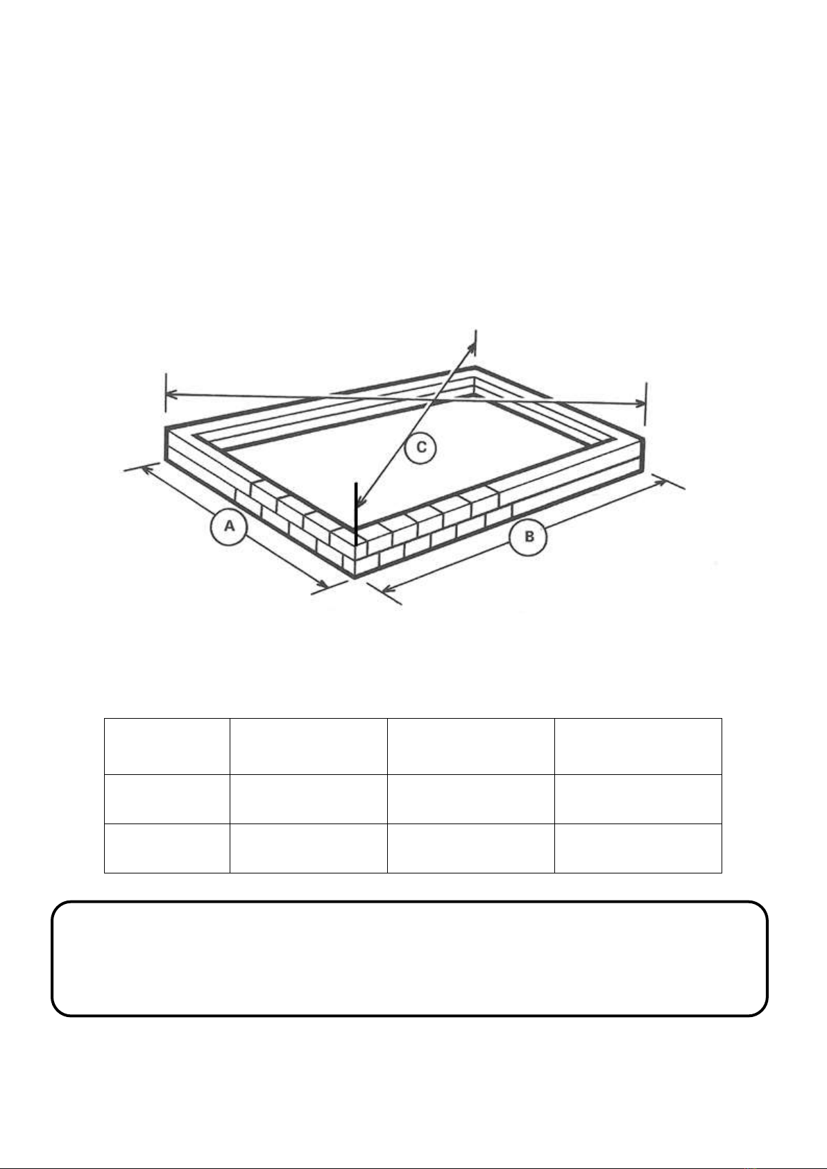
When building your own brick/concrete foundations ensure that they are level and square otherwise your frame will
not be correct and the Polycarb will not fit.
Be sure all four corners of the constructed greenhouse are square before installing Polycarb, and do not install the
Polycarb till the greenhouse is on a permanent foundation.
When inserting the neoprene beading, wetting the rubber or frame with mild soapy water will ease its installation.
Do not place your greenhouse in vulnerable locations such as under trees, playing areas etc.
Children should not play near Polycarb greenhouses. Do not occupy the Polycarbhouse in times of high wind or poor
weather (hail etc)
REMEMBER: Polycarb is fragile, handle with care!. Beware that flying Polycarb from strong wind can/will travel some
distance and can be a dangerous hazard for property and persons surrounding the Polycarbhouse
Gloves should be worn. Protective eyePolycarbes should be worn.
If your greenhouse is a painted one, there are a few 1/8” holes in the ends of some bars. These are jig holes for powder
coating and have no bearing on construction. (Key point).
WHEN CONSTRUCTING A PAINTED MODEL PLEASE TAKE CARE NOT TO DAMAGE THE FINISH BY WORKING ON
CONCRETE OR PATIOS.
Remember to fit the silver aluminium tape to the top edges of the polycarbonate sheeting before fitting them to the
greenhouse
Fit the 20mm square strongbacks (include a 75mm piece of the 20mm x 3mm white double sided tape at each end)
after installing the polycarbonate sheeting.
INSTALLATION INSTRUCTIONS 1.92m MODEL RANGE
The contents of this carton are divided into the different frame assemblies that collectively make up the completed
greenhouse framework.
It is recommended that each frame assembly is fully completed moving on to the next.
The contents are as follows:
1) Two side frames.
2) Rear end frame.
3) Door end frame.
4) Roof Vent.
5) Door.
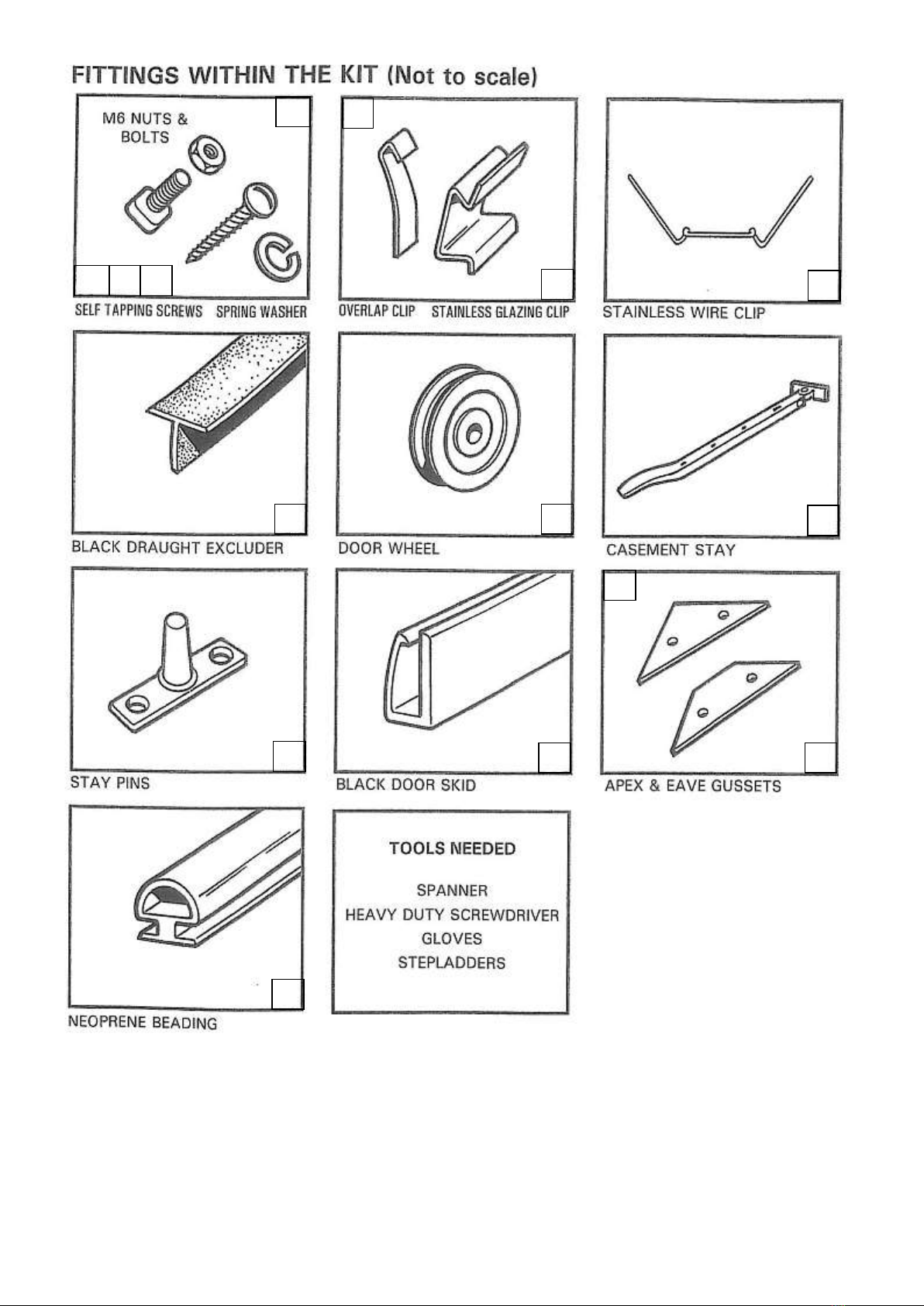
6) Bag of Fittings containing:
a. Nuts & bolts for general assembly.
b. Overlap clips not used for Polycarb.
c. Spring clips not used for Polycarb, wire clips are supplied
d. Casement stay
e. Casement stay nuts and bolts.
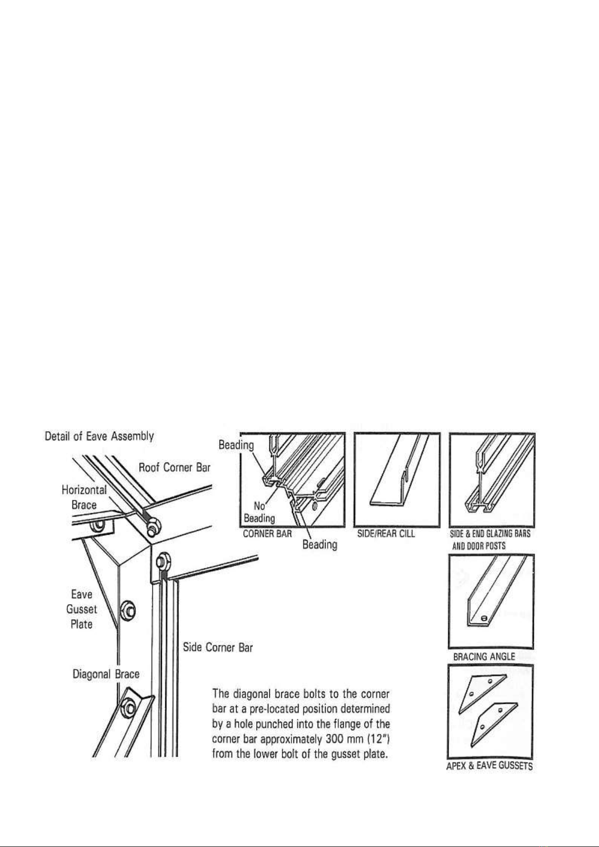
f. Four eave plates (not in the main bag but taped up with the casement stay).
g. Two ridge plates.
h. Two door wheels.
i. Two door guides.
j. Small self-tapping screws.
k. 1 Large self-tapping screw.
l. 1 Spring washer
m. 1 Door catch.
7) Roof bars.
8) Coil of glazing beading
9) One length of ridge
10) Two black rubber draught excluders.

6
For clear identification of parts and the number required please carefully refer to the earlier pages of component drawings
and parts lists.
REDPATH POLYCARBHOUSE BASE DIMENSIONS
For Brick, Block, Concrete or Timber
The dimensions given below may be used to locate the position for your Greenhouse or to lay corner footings if they are
needed.
If a brick, concrete or timber base is to be laid, construct it as shown ensuring that dimensions A & B are not exceeded as these
are precise outside measurements enabling the cill to overhang the edges.
ENSURE that the base is square by measuring across the corners, only when equal is it square.
Check the level using a builder’s spirit level.
MODEL
A (actual base size
width)
B (actual base size
length)
C (actual base size
Diagonal)
2.56m length
1.912m
2.564m
3.198m
3.2m length
1.912m
3.182m
3.712m
Note: Please check with your local council whether a building permit is required for
your Polycarbhouse before construction commences

7
SIDE FRAME ASSEMBLY
When you come to the greenhouse itself start by assembling the side frames first.
The construction of the built in base side is identical to the separate base side except that the base and cill are one piece and it
attaches to the bottom of the side glazing bars in a similar manner to the separate base cill.
1. Lay out the pieces on the ground as though you were standing inside the house, i.e. with the gutter and cill facing
downwards, and the bolt channels of the glazing bars upwards. (Key point). Slide the glazing beading into the V grooves of
the glazing bars.
2. Slide a bolt into each end of each glazing bar. (If you have bought a shelf to go in your greenhouse and you intend to fit it
on a sidewall, use the ½” headed bolts provided with the shelf fittings).
3. Fix the combined eaves bar and gutter to the glazing bars by pushing the bolts through the holes in the eaves bar and
securing with a nut. You do not need to tighten the nuts too much at this stage, but they need to be tight enough to stop
the bolts slipping out of the glazing bar.
4. Fix the cill to the middle glazing bar by pushing the bolt through the hole in the cill unit and tightening as before.
5. Correctly position the cill on the outermost glazing bars by pushing the bolts through the holes in the cill, but do not put the
nuts on yet.
6. Place the angled tie bar over these bolts so that they point outwards towards the ends of the eaves bar. They must be so
arranged that the flat bit of the angle in each case face towards the middle of the house (i.e. the elongated slit will be by the
eaves in one case and by the cill in the other). (Key point).
7. Put the nuts on the bottom bols and lightly tighten.
8. Do the same with the other side frame assembly.
9. Make sure that the glazing bars reach both the cill and the eaves in each case. Tighten all nuts.
10. With the built in base model, slide a bolt into the bolt slot in the built in base section, one at each end. Attach the base leg
(anchor bracket) so that it is pointing downwards. If you are on a patio, you will need to cut the leg off level with the
bottom of the built in base. If you are on soil, the leg will go into the ground at general assembly.
Before assembling any sections slide the required number of bolts into the glazing bars.

8
Lay out the component parts on
the ground as though you were
standing on the inside of a
completed greenhouse i.e. with
the bolt slots uppermost.
SIDE FRAME ASSEMBLY

9
REAR END ASSEMBLY
Components: 1x alloy Cill or Built in Base; 2x Glazing Bars; 2x Roof Corner Bars (marked “R” at the apex);
2x Side Corner Bars (unmarked); 2x Diagonal Cross Ties; 1x Heavy Angle Brace.
From the main bag of fittings you will require the nuts and bolts.
You will also require 2x Eave plates and 1x Ridge plate. These are packed with the Casement Stays and are
separate from the main bag of fittings.
INSTRUCTIONS
1. Lay out the frame as though you were standing on the inside i.e. with the volt slot uppermost. Roof corners marked “R” at
the apex, opposite each other, facing downwards (i.e. “R” on outside). Roof corner bars are mitred at both ends where as
the side corner bars are mitred at one end only (Key Point). The bolt slot is on the inside and faces inwards during initial
construction. If you have a painted greenhouse there is not letter “R” on the corner bar. You must ensure that the
“middle” hole is nearer to the ridge plate than the eaves plate (Key point). Slide the glazing beading into the “V” groove of
the glazing bar and the corner bars. (Do not put beading into the middle slot).
2. Slide two bolts into the bolt channels of each corner bar. These will later be used in the general assembly for fixing the
ridge, eave and cill to the ends. Now secure the ridge Gusset Plate and Eaves Gusset Plates by inserting bolts through the
‘plates’ and into the holes punched in the flange of the corner bar, at the apex and eave.
3. Attach the bottom cill or built in base to the side corner bars by inserting a bolt through the hole in the flange of the corner
bar and into the slot in the cill. (Make sure the angle cill is facing downwards). (Key point).
4. Attach the vertical glazing bars to the cill or built in base by inserting a bolt into the bolt channel of the glazing bars and
locating it with the punched holes in the cill. Before securing the nuts attach the diagonal angle ties to the same bolts as
illustrated. The top of the diagonal angle tie now attaches to the prefabricated holes in the side corner bar.
5. Slide two bolts into the bolt channel at the top of the two vertical glazing bars and secure the second one to the roof corner
bars by inserting the bolt through the punched hole in the flange.
6. You can now attach the horizontal angle brace to the top bolt of the gusset plates and to the other bolts in the glazing bars
you inserted in 5, above.
7. Check that all angles between the cill or built in base and the vertical members are at right angles and that the glazing bars
are right into the angle cill at the bottom. (Key point).

10
REAR END ASSEMBLY
Viewed from inside.
N.B. The roof corner bars are marked “R” on the outside, which indicates that they meet at the ridge. They are also mitred at
both ends.
If you have a painted greenhouse there is no letter ”R” on the corner bar. You must ensure that the “middle” hole is nearer to
the ridge plate than the eaves plate. (Key Point).

11
DOOR END ASSEMBLY
Components: 1x Door End Cill or Built in Base; 2x Glazing Bars; 2x Short Horizontal Braces;
2x Roof Corner Bars (marked ‘R’); 2x Side Corner Bars (unmarked); 1x Door Track Support;
1x Door Track (top); 1x Door Track Angle Stay, (Small Door Track Support).
From the main bag of fittings you will require the nuts and bolts.
You will also require 2x Eave Plates and 1x Ridge Plate. These are packed with the casement stay and are
separate from the main bag of fittings.
INSTRUCTIONS
1. Assemble the frame in exactly the same way as the rear end, up to and including stage 5 of the rear end, but add one extra
bolt into each bolt slot of the end glazing bars.
2. Attach the main door track support (shaped like a letter ‘Z’ to be found with the door panels) to the two glazing bars around
6” down the bar as shown. This ‘Z’ shaped bar must be fitted with the two outside slots facing upwards (as illustrated) not
downwards.
3. The two short horizontal braces attach to the top bolt in the gusset plate and the vertical glazing bars.
4. Stand the frame up and fix the small angle door track support to the right hand side corner bar (viewed from outside). See
front of assembly.
5. Bolt the door track to the main door track support and the door track support angle stay by inserting 4 bolts into the bolt
slot of the door track. Position these through the 3 holes in the door track support above the door opening and the upper
hole of the small angle door track support. When this has been achieved tighten all nuts.
Please note, you only require approx. 200mm of beading in the inside ‘v’ groove of the two end glazing bars.
N.B. Please note carefully the correct position of the main door track support.
The slotted holes at either end are facing skywards not downwards.
At a later stage, when the top door track has been attached, the precise height and position of the track and support can be
established.

12
DOOR END ASSEMBLY
Viewed from inside.

13
DOOR FRAME ASSEMBLY
Components consist of: 2x door glazing bars (1x handed, 1x unhanded)
3x infill panels
2x top & bottom door panels
From the main bag of fittings you require: 2x door wheels
2x clip on nylon door skids
2x lengths of black rubber draught excluder
Self-tapping screws and spring washers.
1. Place the two sidebars on a level surface roughly two feet apart with the bolt slots facing downwards. The top of each
sidepiece has two screw holes in it, the bottom has three (Key point). Slide the glazing beading into the V grooves that face
inwards toward the door panels. (Not in the outside V groove).
2. Place the top, bottom and three infill panels in position as shown by the position of the screw holes in the sidepieces and
the panels. The top panel has the greenhouse name on it. The bottom panel has the edge for the door skids to fit on. The
lower infill panel locks on to the bottom panel. (The flat part of the panels face uppermost).
3. Fix the door together by screwing through the sidepieces into the holes provided in the edge of the panels with the No.8
half-inch self-tapping screws. Do NOT fix the top left hand side screw yet. The screws will go in more easily and without
danger of trying to go crooked if you can put a small amount of grease on the screw before assembling the doors.
Alternatively, you could insert the screws into the screw eyes of the door panels before assembling the door; this would
have the effect of pre-self tapping the panels prior to assembly making assembly easier.
4. Fix the top left hand side with the longer screw provided. Put the screw through the door catch so that the serrated part is
facing outwards and upwards. Next slip tow spring washers on to the screw, and then fix the screw through the side of the
door and into the top panel. (Key point).
5. Make sure all the angles are square and tighten all screws.
6. Fix each door wheel into position by pushing the bolt provided through the centre of the wheel and then through the hole
in the top door panel from underneath (i.e. from the inside of the door). Put the washer over the bolt and secure with the
nut provided, tightening until there is no movement on the bolt. The nuts are lock nuts and are harder to put on than the
normal nuts in general assembly. The wheel will revolve freely because it has ball bearings in it.
7. Slip the nylon door skids on each end of the bottom panel.
8. Turn the door over and insert the black rubber draught excluders in the groove 9bolt slot) in each sidepiece of the door.
Push up to the top of the door and trim off the surplus as the bottom. With a pair of pliers squeeze the groove together at
the bottom so that the rubber will not slip down when the door is in its upright position.
9. Do not fit the door at this stage.

14
DOOR FRAME ASSEMBLY
Do not fit the door to the gable at this stage –wait until the structure is fully assembled prior to glazing.

15
ROOF VENT ASSEMBLY
The roof vent pack has 5 pieces of aluminium: and from the main box of fittings you require 1.83m of glazing beading, 4x nuts
and bolts, 2x casement stay pins, 1x casement stay and 6x M4 stainless steel nuts and bolts.
PROCEDURE:
1. Identify the slam bar and attach the 2 stay pins to the outer side of the angle using the M4 stainless steel nuts and bolts.
2. Lay the 4 edge pieces of the vent on a level surface as though you were on the inside of the vent (with the bolt slots of the
sidebars uppermost and the ‘v’ slots of the bottom rail uppermost. The top rail is arranged in such a way that the squared
off end is to the bottom and the hooked hinge uppermost).
3. Slide the glazing beading into the slots in the side and top rails and trim to suit.
4. Insert a bolt into each end of the side rail bolt slots, put these bolts through the holes in the top and bottom rails, add nuts
and lightly tighten. Check that all joints are secure and that the vent is square, and then tighten up the nuts.
5. Fit the casement stay using the M4 stainless steel nuts and bolts, putting the bolts through the holes in the saddle of the
stay and through the 2 elongated holes in the bottom rail. Hold the nuts in place and tighten the bolts with a screwdriver.
Do the same with the other vents.

16
ASSEMBLY OF GREENHOUSE UNIT

17
ASSEMBLY OF GREENHOUSE UNIT
The first operation is to connect the two side frames to the two end frames to form the outer shape of the completed structure.
Another pair of willing hands would be useful at this stage.
1. Lift the first side frame into its position by the rear end.
2. Slot the eaves bar into the small space between the roof and side corner bar so that the gutter is outside the end frame
and the two flanges that form the angle of the roof and side are inside and tight up against the bolt slots of the roof and
side corner bar. (Key point).
3. The extra bolts that were inserted in the bolt slots during the gable end assembly can now be used.
4. Line up the elongated holes in the flanges of the eaves with the bolt slots and slide the bolts into them. Put a nut on the
top bolt and tighten up. Place the diagonal side angle onto the bottom bolt, put a nut on and tighten up. (Key point).
5. The bottom cill or build in base attaches to the inside of the corner bar. The bolt placed in the corner bar bolt slot at
gable end assembly will slide down into the slotted hole at the end of the cill. For the built in base model the base leg
attached at frame assembly can now be attached to the gable end, in a similar way to its attachment to the side frame.
6. Do the same at the other three corners.
7. Slide the beading into the ridge into the two V slots, and then attach the ridge to the roof corner bars by inserting the end
of the ridge through the small gap in the corner bars at the top. The vertical part of the ridge will be outside and pointing
skywards and the two flanges that form the angle of the roof will be inside, tight up against the bolt slots of the roof
corner bars.
8. Line up the slotted holes at the end of the ridge with the bolt slots, in the corner bars and push the two bolts, previously
inserted during gable end assembly, into the slots. Put on nut and tighten.

18
You can now attach the T-Bar cantilevers, which bolt into the sidebars and roof as indicated.
9. Slide the glazing beading into the V groove of the roof glazing bars. They can now be attached to the ridge and gutter.
Attach them to the ridge first by sliding a bolt into the bolt slot of the glazing bar, inserting it through the hole in the flange
of the ridge. Put a nut on and tighten up. Do the same with the rest of the roof bar.
N.B. remember to omit two roof bars if you have a partition, one each side.

19
Where the vent is to be positioned put an extra one bolt per bar i.e. the vent covers two glazing bars so two extra bolts per
vent. (Key Point). One each bar.
Secure the Tee Bar cantilever bracket to the middle bar of the 2.438m (2 cantilevers)
11. Before sliding the vent into the ridge, slide a piece of black tube into the vent hinge socket. Slide the vent onto the ridge
from either end and into the desired position.
12. Do not fit the door at this stage.
13. The greenhouse is now ready for lifting on to its permanent base.
10. Before bolting the bottom of the roof bar to the flange of the eave bar, insert extra bolts as follows: Then attach the final nut
and bolt to the eave bar as illustrated.
The hinge is a ball and socket joint, the ball
being on the top of the vent, the socket on
either side of the ridge running the full
length of the structure. (Key point).
The vent can go in any position (except
adjacent0 on either side of the ridge. Fit the
slam bar immediately under the vent bottom
rail & secure with the bolts previously
inserted in the roof bars. The precise
position of the slam bar can be determined
by inserting a pane of Polycarb ref A under
the vent and moving the slam bar down to
touch the Polycarb.

20
SECURING GREENHOUSE TO BASE
BRICK BASE, TIMBER OR CONCRETE
Having built your base level and square and to the outside measurements, sit the greenhouse onto the brick base. The 4
cills will lip over the edge of the base and will protrude approx. 7mm all the way round.
Drill through the cill and into the timber/brickwork; screw through the hole using a treated screw and washer. Create an
anchor point every 610mm i.e. at ach glazing bar.
14. PATIO FLOOR
You must make sure that the structure is level and square. Put one pane of Polycarb in each corner of the roof, each
pane must be level with the small Polycarb retaining lip just above the gutter and be running parallel with the roof glazing
bars. Each corner must be the same. If one corner is out the corner diagonally opposite will also be out. By carefully
pushing and pulling each corner diagonally you will be able to see the frame move in and out of square with the Polycarb.
Having established the square of the greenhouse, drill the patio or concrete in the required positions, fit plastic plugs and
screw the brackets firmly to the ground using 35mm x 8mm round head screws.
SOIL FLOOR
Determine the square of the greenhouse as described above, make a mix of concrete and put a couple of shovelfuls
around the base of each stake. When the concrete has gone off back fill with the soil excavated earlier on.
BRICK BASE
When anchoring the frame to a brick base you need to drill through the cill and into the brick. Insert a timber or plastic
plug into the hole in the brick and screw the cill down using a treated screw. Position the hole in the cill as near to the
angle corner as possible so that when you glaze, the screw is on the inside of the Polycarb.
15. FITTING THE DOOR TO THE STRUCTURE
The door slides onto the frame from the left hand side.
Put the door bottom rail into the bottom door track and slide to the right, feed the first wheel into the upper door track
and move further to the right until the black draught excluder butts up to the end glazing bars. Carefully ease the door
past the glazing bar and feed in the second wheel. Push further to the right until both draught excluders are butting up to
both end-glazing bars. Carefully ease the door past the two glazing bars. The door will now run quite freely. To square
up the door with the spacing, undo the upper bolts holding the door track. There is a little play to facilitate “fine tuning”
of the door. N.B. Sometimes the door can be a little stiff prior to glazing but once the Polycarb has been inserted (the
last job of the construction) the extra weight will make for smooth running. (Key point).
Angle Brackets
The aluminium angle brackets are bolted to the cill and then with the use of screws are secured to the base.
Timber screws are available on request.
Table of contents
Other Redpath Greenhouse Kit manuals
Popular Greenhouse Kit manuals by other brands

Harbor Freight Tools
Harbor Freight Tools 94515 Assembly instructions

Konifera
Konifera SF2500 Assembly instructions

Palram
Palram Automatic Vent Opener Assembly instructions

Palram
Palram CANOPIA SANREMO 3x3 How to assemble

Elite Greenhouses
Elite Greenhouses TITAN K800 Instructions & Illustrations

Halls
Halls Magnum 108 manual

VOLYA
VOLYA PRIMA 4 Assembly manual

Costway
Costway GIANTEX GT2978 user manual

Elite Greenhouses
Elite Greenhouses 6'3" WIDE HIGH EAVE Instructions & Illustrations

Palram
Palram Eco Grow manual

Elite Greenhouses
Elite Greenhouses 6'3" WIDE CRAFTSMAN Instructions & Illustrations

New Leaf
New Leaf GH2013 instructions