manuals.online logo
Brands
  1. Home
  2. •
  3. Brands
  4. •
  5. Redpath
  6. •
  7. Greenhouse Kit
  8. •
  9. Redpath Domestic Tunnel Series User manual

Redpath Domestic Tunnel Series User manual

Effective from 12-Nov-20 Page | 1
PLEASE READ IN FULL BEFORE PROCEEDING
Suggested Tools:
Step ladder / Saw-stools
Knife / Scissors / Secateurs / Hacksaw
Tape Measure, Hammer or Mallet
Builders level / String line / Line level
Timber ground pegs / temporary bracing
Safety Glasses / Gloves / Earmuffs
Cordless or electric drill / drill bit
Marker Pen / Pencil
Note: A second person can be useful to have available when fitting the cladding or lifting or temporarily any heavier or larger parts.
Select a site:
A level site is desirable. Choose a site that offers some protection for the Tunnelhouse from strong winds. Face the door away from
the pre-dominant wind if possible. The Tunnelhouse is already partly pre-assembled. We suggest you take your time and allow
yourself a weekend to erect the frame and fit the covering. Call us on Free Ph. 0508 733 728 with any questions during assembly
For standard sites, place a 600mm ground peg at 1m apart along the length and width of the building. If your ground is sandy or loose
or if you have a windy site, then ground pegs will need to be longer or spaced closer together to ensure that the Tunnelhouse is well
secured to the ground. (See below Foundation and base rail(s))
Foundation and Base Rail(s)
Usually it is best to complete the foundation of the Tunnelhouse before placing the Tunnelhouse in place. If using ground pegs only
hammer these in before the cladding is fitted.
Redpath Pacific Ltd
PO Box 9058
16 Bounty Place
Palmerston North 4414
Free Ph 0508-733-728
Effective from 12-Nov-20 Page | 2
You will need to select suitable screws to fasten the base rails to your base or ground pegs. (The longer tunnelhouses 12m or over
are best to have ground pegs concreted in place)
Typically, a ground timber peg of 75mm x 50mm x 600mm is sufficient see (Pic GP1) below. Hammer these into the ground at
approximately1m spacing. see (Pic GP2) below
If your chosen site has high wind exposure or has soft soil –then place ground pegs closer together.
You may also wish to consider using concrete to secure your ground pegs if a more durable foundation is preferred. The models
sized 12m or more are best to be concreted.
Interior base foundation dimensions (if you wish to build an additional base frame):
The tunnelhouse is already supplied with alloy base rails, however your ground is undulating you may wish to build an additional
timber frame base for the tunnelhouse using 100mm x 50mm or 150mm x 50mmm timber rails. The dimensions for a timber frame
option are shown below. (Extra base materials are not supplied)
Ensure that dimensions A & B are accurate! - As these are precise inside measurements enabling the interior base rail of the
tunnelhouse (supplied) to match the inner edges of your timber framed base. Ensure that the base is square by measuring across
the corners (C) in both directions.
Check the level using a builder’s spirit level –in directions (A), (B) & (C) The building & its cladding relies on the buildings base
being level in all directions. If using Timber for the base, the base will need to be secured to the ground with pegs spaced at
approximately 1m apart with typical 600mm depth.
Note that adding a base timber rail system will increase the height of the tunnelhouse and may require you to step ‘over’ the taller
base.
(Pic GP1) Ground peg connection to base rail (Pic GP2) Ground peg spacing
Effective from 12-Nov-20 Page | 3
INTERIOR MEASUREMENTS –if making your own timber base
MODEL: Nominal frame size
A(actual internal base size width)
B(actual internal base size length)
C(actual internal diagonal –check)
2.36m x 1.5m
2300mm
1532mm
2764mm
2.36m x 3m
2300mm
3032mm
3806mm
2.36m x 4.5m
2300mm
4532mm
5082mm
2.36m x 6m
2300mm
6032mm
6456mm
2.36m x 7.5m
2300mm
7532mm
7875mm
2.36m x 9m
2300mm
9032mm
9320mm
2.36m x 10.5m
2300mm
10532mm
10780mm
2.36m x 12m
2300mm
12032mm
12250mm
2.36m x 15m
2300mm
15032mm
15207mm
2.36m x 18m
2300mm
18032mm
18178mm
2.36m x 21m
2300mm
21032mm
21157mm
2.36m x 24m
2300mm
24032mm
24142mm
Stage 1 Stand up the door end and the louvre end walls.
The Tunnelhouse is supplied with end frames pre-assembled. With assistance stand these up in a vertical position (triangular
brackets face to the inside).
The side base rails finish flush with the front face of the end base rails. see (Pic BR1) below
The groove in the front base rail faced to the inside , the groove in the rear wall base rail faces to the outside.
Hold the ends vertical and fit the screws to the four corner brackets to attach the side base rails. see (Pic BR2) below. Take care
not to over torque and “spin” the screws in the alloy base rail.
Effective from 12-Nov-20 Page | 4
Corner side base rail finishes flush with end rails (Pic BR1)Internal corner brackets (Pic BR2)
Stage 2 Stand up the internal hoop(s).
For the 15m,18m, 21m & 24m models, slide the 300mm x 25mm x 25mm sleeve into each end of each internal hoop and secure
with a single screw. Stand up the internal hoops and slide their ends into the saddles that are already fitted to the inside face of the
side base rails see (Pic SBS1).
Install the Polyguard 40mm adhesive felt tape to the top face of the internal hoops only to help prevent cover chaffing (do not
install to end hoops) see (Pic POL1) below
For the 15m, 18m 21m & 24m models fit the horizontal collar tie to each central hoop
NOTE 1: We suggest not securing the internal hoops into place with the two screw(s) at their base saddles until after the
covering has been fitted. This will allow the hoops to be lifted ‘upward’ slightly after the covering is in place which will assist with
tensioning of the covering.
NOTE 2: If your Tunnelhouse includes a roof vent(s) the internal hoops where the vent is to be placed will need to have the hoops
positioned so that the ‘flat’side face (not grooved) face toward each other.
Effective from 12-Nov-20 Page | 5
(Secure these internal hoop screws after the cover installed) (Pic POL1) - Place adhesive felt onto top edge of internal hoops
Stage 3 Locate the lengthways purlins.
There are three purlins on standard models and five purlins on the longer & high wind kit models as shown below. Use the 25mm
saddles & screws to secure these (See P1 & P3 below). Locate a purlin at the ridge, midway in the roof curve as shown below. For
high wind kit models also place a purlin 125mm up from the base rail. Place 24mm Polyguard along the length of all purlins to their
outside face. Fit 24mm Polyguard end dwangs at both ends:
NOTE:If an optional sidewall shelf unit is to be fitted, the lowest purlin should be placed above the shelf bracket height position
Wrap two layers of Polyguard tape around
Purlin ends (P1) purlin ends to prevent wear on covering (P2) Saddle holding side purlin in place (P3)
The purlin for high wind
kit models include a
purlin each side here
1250mm above the
base rail
(P1) &
(P2)
(P4)
(P5)
Effective from 12-Nov-20 Page | 6
Ridge purlin (P4) Interior purlin fitted (P5) Side view of purlins fitted (not high wind model)
Wall bracing
Fasten the lower end of the side wall brace to the inside face of the base rail near to the side base rail saddle using one screw. see
(Pic B1 & B2)
Fasten the top end of the wall brace to the inside face of end hoop. (Pic B3) Position it so that the end of the brace does not
protrude out from the end wall otherwise the end wall cover when fitted may touch the corner and be damaged. Wrap a small piece
of Polyguard onto the top end of the wall brace to protect the end wall cover.
Note: If your Tunnelhouse has a high wind kit supplied it will include two end wall angle braces at each end. The end wall braces
are slightly shorter than the 4 x sidewall braces but are fitted in the same manner. NOTE: The end wall high wind kit angle brace
may require re-positioning and shortening if you have chosen to fit an optional shelf unit.
(Pic B1) (Pic B2) Secure the side wall brace (Pic B3)
Stage 4 –The cover holding systems and fitting the cover(s)
There are two types of cover holding systems used on this tunnelhouse. You will note that the shape of the grooves in the
aluminium end frame and base rail & door is differs between the two types.
System 1: Lockstrip is used for the top face and front face of the end hoops. It is also used on the vent upstand rails. Lockstrip
has a green coloured strip continuous insert and grey coloured “L” shaped locking clips spaced every 200mm. Thee MUST face in
the direction shown ((Pic L2) See below
(Pic L1)below shows, the pre-cut 200mm length pieces of the lockstrip insert. These are fitted to the front faces of the curved parts
at both ends only. Do not use them at any other location.
Lockstrip insert is also supplied in full 1.5 lengths (please trim these to length). There is video link on the Redpath web site
http://www.redpath.co.nz/commercial-greenhouse-accessories/greenhouse-film-clipping-systems.html
IMPORTANT & COMMON MISTAKE !. Please take note that the longest ‘leg’ of the lockstrip insert and the longest leg of the grey
clip always face toward the cladding……
Effective from 12-Nov-20 Page | 7
(Pic L1): Use the 200mm green inserts in the front (Pic L2): Shows the positioning of the covering (red), Insert (green)
Face of the curved part at each end hoop only and Lockstrip clip (Grey)
System 2: Duralock The Duralock groove inserts are made up of 1.5m white ‘channel shaped’ inserts and a rectangular white
‘bead’ insert. These are inserted into the Duralock aluminium groove that is located along the outside face of the side base rail and
rear wall base rail, On the INSIDE face of the front base rail, The door, and the end framing dwangs etc.
How to assemble Duralock:
See video link on Redpath web site http://www.redpath.co.nz/commercial-greenhouse-accessories/greenhouse-film-clipping-
systems.html
1. Pull the cover and tension it over the jaw of aluminium.
2. Important: Ensure that the channel insert has the locking lug (A) facing forward
3. Insert the channel strip by tilting it as shown below and as you press it down and into the groove release the tension from behind
to allow the channel insert to drop into place
(A) Locking Lug Forward (B)Tilt Channel Insert (C) Fully Seat Channel Insert, then fit Bead
The “channel” insert with its front “Locking Lug edge” facing forward is inserted first. Tilt the front edge down (B) & whilst easing
cover tension from behind locate the channel insert into the alloy groove using a rolling motion. Leave a small gap between strips 5-
10mm to allow for heat expansion. Check that the channel is fully “open” in readiness for the bead insert (C). trim the insert to length
using secateurs
Install the Locking Bead
4. Ensure that the channel is full seated & that the Jaw “of the channel is fully open before pressing the locking bead into place.
5. Press one end of the locking bead with its rounded edge facing down fully into position. A softheaded mallet may be used gently
to assist the rest of the bead strip into place.
Below picture shows all parts of Duralock 2 assembled
(Fig 1)
Cover
Bead
Channel
Base Rail
Base Rail
Channel
Bead
Effective from 12-Nov-20 Page | 8
FITTING THE COVERS TO THE TUNNELHOUSE
There are four pieces of covering supplied for this building: The roof and sidepiece is one part (largest), there are two x end
pieces (3m x 3m), and one x door piece (1m x 2m). The Polyshade models will have shadecloth on the end walls and door, The
shadehouse models will have shadecloth on all surfaces.
Install the clear covering on a warm, calm day, (this makes the work and the tensioning of the covering easier).
Note: When fitting the clear roof part cover it should have the printing on the cover facing to the inside.
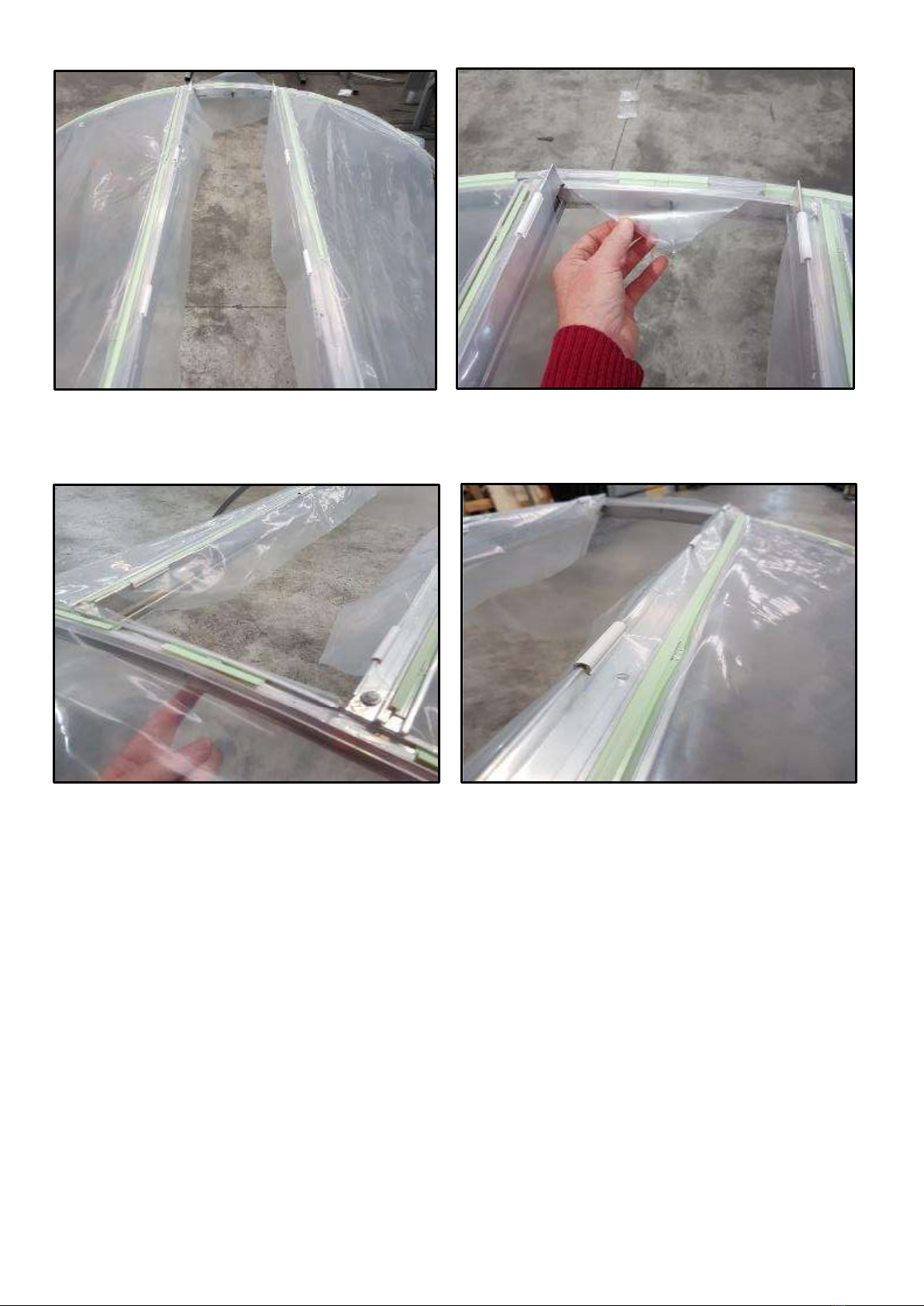
DOOR COVER –use the Duralock holding system
Lay the door frame on the ground with Duralock groove facing upward and place the 2m x 1m door cover in approximate position
You will need to cut the Duralock inserts with a pair of secateurs to suit the length of the frame work. The Duralock insert will stop
short approximately 25mm from each end.
You will begin by fitting the Duralock insert to the top door rail firstly, - then the bottom door rail (pulling the cover tight as you do
so). Then install the inserts to the two longer side door edges. (begin in the middle and work toward the corners) see (Pic page
8)
Locate the channel shaped insert strip fully as above then tap in the ‘bead’part with a rubber mallet
ROOF AND SIDEWALL COVER, use the Lockstrip holding system for the end hoop parts and Duralock 2 holding system
is used for the side base rails
The roof and sidewall cover is supplied in one piece. The width is 6m and the length will suit the size of the Tunnelhouse that you
have ordered.
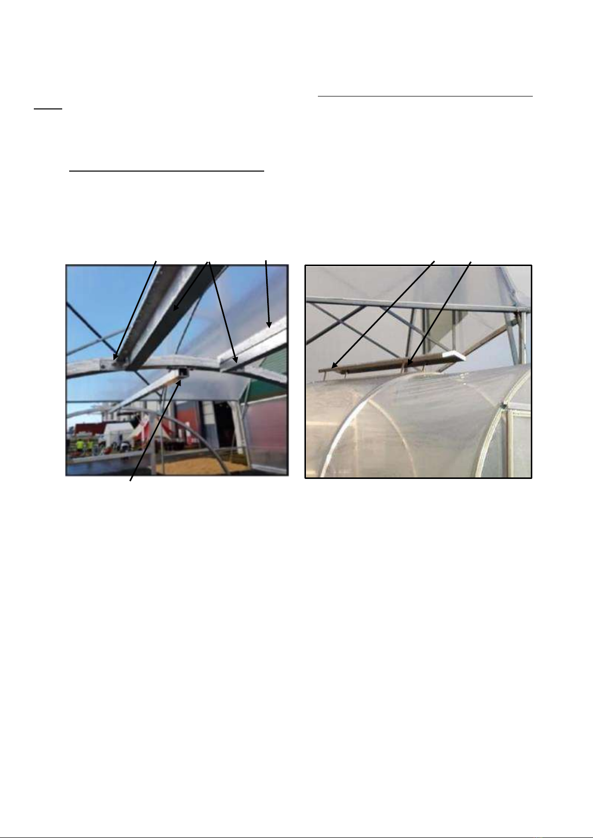
If your Tunnelhouse includes a roof vent please install the roof vent kit before-hand (see instruction below), You will need to cut
and remove the ridge purlin when you choose to locate the roof vent.
Before fitting the roof cover remove the cap vent part plus the aluminium pivot arms and handle see (Pic V2) above
(leaving the two vent rails and upstand in place (See Pic V1 below)
TIP: You can place a temporary rope or strap along the full length of the Tunnelhouse 750mm each side of the ridge on top of the
hoops, to help support the roof cover whilst you distribute it across the Tunnelhouse. The rope helps to stop the covering from
draping down between the hoops, and assists with you placing tension on the cover.
NOTE: If your Tunnelhouse has a roof vent take care not to catch the cover on the vent rail upstands see (Pic V1) above when
laying it out into position.
NOTE: The print name on the cover should face to the inside of the Tunnelhouse so that the text reads correctly (left to right)
Reminder : As mentioned in stage 2 (page 5) do not fit the two screws in the base rail saddles that hold the internal hoops in
place, with these two screws not in place the hoops will sit down a little lower, and they can then be raised back up into place
after the covering has been fitted which will add tension to the covering
Unfold the cover and lay it out over the Tunnelhouse so that it rests in approximate position with an equal amount of excess film
draping over each end hoop and each side base rail.
Begin at one end of the Tunnelhouse and install the Lockstrip holding system starting at the apex and working to the left and right
down each side of the end hoop. See the lockstrip video on the website.
Go to the other end and pull the cover tight along the length of the ridge. Install the Lockstrip holding system starting at the apex
and whilst pulling the cover as tight as possible –work your way to the left and right installing the Lockstrip holding system down
each side of the end hoop.
Now move to the side base rails. These use Duralock 2 clipping system.
TIP: Read the Duralock 2 clipping system in these instructions and also see this link for an assembly video
http://www.redpath.co.nz/commercial-greenhouse-accessories/greenhouse-film-clipping-systems.html
Begin at the center & start inserting the U shaped Duralock channel insert + bead whilst tensioning the cover as much as
possible. Work your way to the left and right toward the ends of the building.
TIP: Sometimes it is simpler to lift the entire side of the Tunnelhouse up in the air and rest it on blocks or sawstools –as this can
make it more convenient to insert the Duralock clip.
ROOF VENT: If the roof vent option is included with your model, you will complete this section before fitting the roof and
sidewall cover (disregard this section if you have no vent)
If the roof vent option is included in your design then you should Partially install this prior to fitting the roof and sidepiece of covers.
Effective from 12-Nov-20 Page | 9
NOTE: The roof vent may be positioned in any of the Tunnelhouse sections; however, you cannot fit the roof vent in a section
directly beside another section that might already have a roof vent.
(This is because the ends of the vent require clearance for an overlap.
NOTE: When you have decided which section to place the roof vent in, you will need to cut and remove the ridge purlin in that
section. see (Pic V1) next page
1. Before fitting the roof and side covering - Lift the roof vent complete into place at the apex of the Tunnelhouse, - the ends of
the roof vent upstands will rest on the top face of the hoops.
2. Screw the four “L brackets” onto the flat side face of the tunnel hoops. see (Pic V1) next page
3. Before you fit the cover onto the building stage 4. - You will need to disconnect the roof cap by undoing the four bolts that
hold the vent in place on the upstand. Remove the roof folded cap and aluminium vent arms + handle completely. (this will
be re-fitted later)
4.
With the vent removed, you can now proceed to fit the main roof cover.
(Pic V1) Vent “L” Bracket x 4, Vent rails Vent Upstands (Pic V2) Roof vent cap and Vent arms + Handle
Note: The ridge beam purlin should be removed from the vent location space; the vent rails replace the ridge purlin in the vent space.
IF YOU HAVE A ROOF VENT OPTION
After the main roof and sidewall covering has been fitted, - you can re-fit the cap vent (see pictures below)
1. In the section where the vent is to fit –Use a knife or scissors to slice the cover at the center apex for the length of the roof
vent rails
2. Then slice the cover toward the corners of each vent rail. See (Pic V4) below
3. Insert the Lockstrip holding system into each of the vent upstand rails
4. Insert a 100mm piece of Lockstrip insert + clips x 2 into the top edge of the hoops at each end of the roof vent (this goes
between the vent rails)
5. Secure the edge of the cover onto the top edge of the upstand using the white Omega clips provided see(Pic V5) below
6. Trim the excess film behind the Omega clip and also at the end of the roof vent opening away
7. Re-locate the roof cap and aluminium arms + handle up into place and re-connect the nuts/bolts/washers to the upstand.
8. Test the roof vent for open / close action and adjust if needed.
Effective from 12-Nov-20 Page | 10
(Pic V3) View of the roof vent rails with covers fitted Cut the cover –between the vent rails (angle into corners)
(Pic V4) Shows cover cut away and 100mm piece of Lockstrip (Pic V5) shows omega clip fitted to upstand –which holds the
insert + clip to hold the end in place tail of the cover behind the vent rail and acts as a flashing
(remove the piece of Polyguard if fitted)
END AND LOUVRE END WALL COVERS –use the Lockstrip holding system for the hoop and end wall stud parts and
Duralock 2 holding system for the base rail part.
Each end cover is supplied in a 3m x 3m piece
The pre-cut 200mm pieces of green insert are only used on the front faces of the curved part of the end hoops
Find the center of one edge of the end covers and hang this so that the top edge is more-or-less parallel to the ground and has
its center approximately in position at the apex of the hoop.
Fit one 200mm pre-cut piece of lockstrip insert and “L” clip into the front face of the frame to temporarily hold the end cover.
Whilst placing some tension on the covering, Fit another 200mm pre-cut piece of lockstrip at the point where the curve of the end
hoop stops and the straight part of the sidewall begins (approximately the 9 o’clock and 3 o’clock position if looking at the face),
then whilst tensioning the covering position a 200mm pre-cut piece of lockstrip midway between the two inserted pieces.
Whilst tensioning the covering fill in all of the remaining front face of the curved part of the end hoop see (Pic L1) using the
supplied 200mm pre-cut pieces.
For the remaining straight part of the end hoop frame, cut a piece of lockstrip insert to suit the remaining length and whilst placing
some tension on the covering install the insert and “L” clips. (“L” clips are spaced at Approx. 200mm)
The base rail at each end uses the DURALOCK 2 cover holding system, please read the Duralock 2 instructions.
Effective from 12-Nov-20 Page | 11
With end hoop and base rail secured, - you can ‘cut out ‘The door and the louvre openings. Be sure to cut the opening on the
correct side of the framework so that you have some film to hold onto and tension whilst you fit the Lockstrip inserts and clips into
the end studs and around the louvre frame
Note: Try to avoid wrinkles in the cover whilst clipping. If you get excessive wrinkles, release the holding system and re-fasten.
‘Work” any wrinkles toward the corners if possible.
Note: If the insert “jumps out” in windy conditions –it is possible that the insert has been installed backwards or upside down.
Please check the lockstrip holding system drawing, see (Pic L2) Page 7 for the correct parts assembly final position.
Stage 5. Fitting the louvre window
The louvre mechanism has already been fitted as part of the pre-assembly service by Redpath.
After the tunnel has had its covers fitted - carefully slide the three polycarbonate sheets into each holder. Then fit 1 x 570mm
aluminium strongback across each blade (remove backing tape and adhere to the blade across its centre. This is to stop the
individual blades bending from wind load.
Stage 6. Door
Note: Do not fit the door track or the door itself to the building until after the door end wall cover has been fitted.
Fitting the door and door track
1. Place a piece of the Duralock 2 bead on top of the base rail in the door opening to act as a packer.
2. Slide the door track onto the two door rollers that are already attached to the door frame
3. Lift the door track complete with door attached into approximate position (resting it onto the packers)
4. Lift up the door track slightly so that the weight of the door is suspended on the track.
5. Screw through the door track top plate and into the right hand end stud. see (Pic D4 ) below
6. Raise the left hand end of the door track so that the clearance at the bottom of the door is similar on both sides. Place a screw
through the door track top plate at the left hand end stud point.
see (Pic D5) below
7. Remove the lower packer and check that the door slides and clears the base rail.
8. Screw three more screws (evenly spaced) through to the door lintel to fully support the track.
9. Place one screw through to the end hoop at the left hand end of the door track. Check the door sliding action.
10. Place the two door guides each side of doorway.
11. Place a screw through each end of the door track where the door rollers slide to act as a stop for the door rollers so that the
door cannot slide off the track at its ends.
12. Fit the door handle. see (Pic D2) below
Note: If you want the door to slide to the right instead of the left, you will need to modify the pre-set location of the door rollers.
(Please call for more details Ph: 0508 733 728
Adhere strongback alloy angle
across center of each louvre blade
to stiffen the polycarbonate
Louvre mechanism is already fitted
Effective from 12-Nov-20 Page | 12
Door Handle –(Pic D2)
Exterior view of door track (Pic D1) slot into groove and place 2 x screws Door guide bracket (Pic D3)
(Pic D4) (Pic D5)
Tunnel Maintenance:
Clean your greenhouse once per year to remove algae / pollen / dirt. Use dishwashing liquid and soft broom. You may use a water
blaster but use caution with being too close to the covering. There is also a product name “Surrender” – available from Fruitfed
supplies NZ, spray this on 24hours prior to rainfall.
Wash down the interior of the tunnel house to prevent any fertilizer or chemical degradation.
Patch any holes or tears in the cover as they occur with all-weather tape or Patchbond tape.
Check annually that foundations are secure, all bracket screws are tight, replace any missing or broken screws, check that door rollers
and vent mechanisms are operating smoothly. Call Redpath if you need any spare parts for your Tunnelhouse.
General assembly images from archives: Note your model may differ in length and options shown.
Base pad prepared ready for construction Purlins fitted and end covers fitted.
Effective from 12-Nov-20 Page | 13
General view 7.5m model, single front door, 1 x roof vent, high wind kit.
General view interior 6m model, high wind kit, interior
Effective from 12-Nov-20 Page | 14
General view –3m model with high wind kit fitted, internal raised gardens included
General view , 6m model, rear wall + louvre

This manual suits for next models

11

Other Redpath Greenhouse Kit manuals

Redpath Urban Series User manual

Redpath

Redpath Urban Series User manual

Redpath Domestic tunnelhouse Greenhouse 2.74 User manual

Redpath

Redpath Domestic tunnelhouse Greenhouse 2.74 User manual

Redpath Statesman Series User manual

Redpath

Redpath Statesman Series User manual

Redpath Tunnelhouse Mk2 User manual

Redpath

Redpath Tunnelhouse Mk2 User manual

Redpath The Beast User manual

Redpath

Redpath The Beast User manual

Redpath Tunnelhouse User manual

Redpath

Redpath Tunnelhouse User manual

Popular Greenhouse Kit manuals by other brands

Juliana Grand Oase 13,0 Assembly instruction

Juliana

Juliana Grand Oase 13,0 Assembly instruction

Parkside PTB 1 A1 Assembly, operating and safety instructions

Parkside

Parkside PTB 1 A1 Assembly, operating and safety instructions

Grandio 2015 EARTH & GRASS L-BOLT ANCHORING KIT quick start guide

Grandio

Grandio 2015 EARTH & GRASS L-BOLT ANCHORING KIT quick start guide

Greenhouse 10 LE SYSHR 10X6 manual

Greenhouse

Greenhouse 10 LE SYSHR 10X6 manual

Weather Guard 63012 Assembly instructions

Weather Guard

Weather Guard 63012 Assembly instructions

Grow Freedom Greenhouse Base Preparation Instructions

Grow

Grow Freedom Greenhouse Base Preparation Instructions

juwel Biostar Protect 1000 manual

juwel

juwel Biostar Protect 1000 manual

Vitavia VM0003-I Assembly instructions

Vitavia

Vitavia VM0003-I Assembly instructions

northern polytunnels Hobby instructions

northern polytunnels

northern polytunnels Hobby instructions

Floria RC Series manual

Floria

Floria RC Series manual

Westfalia ZBH-J-047 instruction manual

Westfalia

Westfalia ZBH-J-047 instruction manual

Juliana Senior manual

Juliana

Juliana Senior manual

Floria garden products Classic Plus Assembly instructions

Floria garden products

Floria garden products Classic Plus Assembly instructions

ACF Greenhouses Cross Country Series instructions

ACF Greenhouses

ACF Greenhouses Cross Country Series instructions

VOLYA FERMER-4,2 Assembly manual

VOLYA

VOLYA FERMER-4,2 Assembly manual

VOLYA VENT Assembly manual

VOLYA

VOLYA VENT Assembly manual

VegTrug Nursery manual

VegTrug

VegTrug Nursery manual

oGrow OGAL-666A manual

oGrow

oGrow OGAL-666A manual

manuals.online logo
manuals.online logoBrands
  • About & Mission
  • Contact us
  • Privacy Policy
  • Terms and Conditions

Copyright 2025 Manuals.Online. All Rights Reserved.