manuals.online logo
Brands
  1. Home
  2. •
  3. Brands
  4. •
  5. Redpath
  6. •
  7. Greenhouse Kit
  8. •
  9. Redpath Statesman Series User manual

Redpath Statesman Series User manual

This manual suits for next models

2

Other Redpath Greenhouse Kit manuals

Redpath Domestic Tunnel Series User manual

Redpath

Redpath Domestic Tunnel Series User manual

Redpath The Beast User manual

Redpath

Redpath The Beast User manual

Redpath Tunnelhouse User manual

Redpath

Redpath Tunnelhouse User manual

Redpath Domestic tunnelhouse Greenhouse 2.74 User manual

Redpath

Redpath Domestic tunnelhouse Greenhouse 2.74 User manual

Redpath Tunnelhouse Mk2 User manual

Redpath

Redpath Tunnelhouse Mk2 User manual

Redpath Urban Series User manual

Redpath

Redpath Urban Series User manual

Popular Greenhouse Kit manuals by other brands

Dancover TITAN Arch 196 manual

Dancover

Dancover TITAN Arch 196 manual

ACD PRESTIGE MR3 H manual

ACD PRESTIGE

ACD PRESTIGE MR3 H manual

Vitavia VA0040-TRP Assembly instructions

Vitavia

Vitavia VA0040-TRP Assembly instructions

VegTrug Nursery manual

VegTrug

VegTrug Nursery manual

Riverstone Networks Monticello 041315V Assembly instructions

Riverstone Networks

Riverstone Networks Monticello 041315V Assembly instructions

CLIMA POD Spirit V7 Series Assembly instructions

CLIMA POD

CLIMA POD Spirit V7 Series Assembly instructions

Vitavia GAIA JUMBO Assembly instructions

Vitavia

Vitavia GAIA JUMBO Assembly instructions

Palram Harmony 6'x4' Assembly instructions

Palram

Palram Harmony 6'x4' Assembly instructions

ClearSpan Storage Master 104598 instruction manual

ClearSpan

ClearSpan Storage Master 104598 instruction manual

Sproutwell GRANGE - 5 Assembly instructions

Sproutwell

Sproutwell GRANGE - 5 Assembly instructions

STC Easy Grow 6x12 Greenhouse Assembly instructions

STC

STC Easy Grow 6x12 Greenhouse Assembly instructions

Growhouse Lean To 6 x 8 Erection and Glazing Instructions

Growhouse

Growhouse Lean To 6 x 8 Erection and Glazing Instructions

Riverstone Networks Grower's 181010V Assembly instructions

Riverstone Networks

Riverstone Networks Grower's 181010V Assembly instructions

GrowSpan 500 Series manual

GrowSpan

GrowSpan 500 Series manual

Stocker 9641/2 manual

Stocker

Stocker 9641/2 manual

Outsunny 845-421V02 manual

Outsunny

Outsunny 845-421V02 manual

ACD Piccolo 03 manual

ACD

ACD Piccolo 03 manual

Riverstone Networks MONT-8 Assembly instructions

Riverstone Networks

Riverstone Networks MONT-8 Assembly instructions

manuals.online logo
manuals.online logoBrands
  • About & Mission
  • Contact us
  • Privacy Policy
  • Terms and Conditions

Copyright 2025 Manuals.Online. All Rights Reserved.

PLEASE READ Instructions & Illustrations for the Redpath Statesman
Series Polycarbonate greenhouse 2.57m x 3.80m or 2.57m x 5.04m
16 Bounty Place, Kelvin Grove, Palmerston North 4414 Freephone: 0508 733 728
www.redpath.co.nz Effective from 15-Oct-20
2
3
(IF SUPPLIED)
4
PARTS LIST –FOR POLYCARBHOUSE SERIES
2.57m x 3.80m 2.57m x 5.04m
1. Ridge 1 1
2. Gutter/Eave 2 2
3. Side Cill 2 2
4. Side Angle 4 8
5. Door End Cill 1 1
6. Rear End Cill 1 1
7. Rear End Angle 1 1
8. Short Door End Glazing Bar 2 2
9. Long Door End Glazing Bar 2 2
10. Diagonal Angle 2 2
11. Short Horizontal Angle 2 2
12. Medium Horizontal Angle 2 2
13. Short Rear End Glazing Bar 2 2
14. Long Rear End Glazing Bar 2 2
15. Diagonal Angle 2 2
16. Corner Bars in 2 packs of 4 8 8
17. Roof Bars 10 14
18. Side Bars 10 14
19. Roof Diagonal Angle 2 4
20. Roof Vent Pack (made up of 2 side rails, 2 4
1 top rail, 1 bottom rail, 1 slam bar)
21. Door Panel Pack (made up of 1 top panel, 1 1
1 bottom panel, 3 intermediate panels,
1 Door track support)
The Double Door Panel Set does not have the door track support in it –it has double the amount of panels
22. Door Posts (In pairs) 1 1
N.B. Double Door has 2 pairs
23. Cantilevers T-Bar-Brace - Small 3 -
- Large 6 13
24. Bag of Fittings 1 1
25. Glazing Beading 400 500
26. Gusset Plates - Eave 4 4
- Ridge 2 2
27. Casement Stays 2 4
28. Top Door Track 1 1
29. Polycarbonate sheeting (see last page of instructions) included cut to length
30. 20mm square aluminium strongbacks + tape included (tape not fitted)
31. Aluminium tape to seal the top edges of the polycarbonate included (not fitted)
The polycarbonate is supplied in pre-cut lengths. The aluminium sealing tape (supplied) will need to be
applied to the top edge of each sheet as you fit them. The aluminium strongbacks, will also need to be
applied in locations shown to prevent polycarbonate ‘bend’ and give superior wind resistance (add a 75mm
piece of the double sides tape to each end of the 20mm square aluminium strongbacks)
Tapes together
And marked “side”
Taped together and
marked “Door End”
5
REDPATH POLYCARBONATE GREENHOUSE BASE DIMENSIONS
(Materials not supplied)
Base material may be: Timber, Brick, Block, or Concrete
(Dimensions shown are to the exterior edges)
The dimensions given below are for the base & ground anchoring system of your Polycarb house. You will need to supply the
materials & construct these using Concrete, Brick or Timber. Ensure that dimensions A & B are not exceeded! - As these are
precise outside measurements enabling the aluminum base cill of the Polycarbhouse (supplied) to overhang the edges of your
base. Also ensure that the base is square by measuring across the corners (C) in both directions. Only when this measurement is
equal is the base square!
Check the level using a builder’s spirit level –in directions (A), (B) & (C) The building & its Polycarbonate cladding relies on the
buildings base being level in all directions. The height of the base is typically up to 150mm above ground level, with a portion of
the base being below ground level. If using Timber for the base, the base will need to be secured to the ground with pegs spaced
at a width & depth to suit your chosen sites wind exposure & ground conditions.
MODEL: Nominal frame size
A(actual base size width)
B(actual base size length)
C(actual diagonal –check)
Statesman 2.43m x 3.65m
2570mm
3804mm
4591mm
Statesman 2.43m x 4.87m
2570mm
5040mm
5657mm
Note: Please check with your local council whether a building permit is required for
your Polycarbhouse before construction commences
6
HELPFUL HINTS & ADVICE
Please take your time and be sure to read all instructions carefully before assembling. The Polycarbhouse structure does often
require at minimum an “experienced DIY” type person or a semi-skilled builder to assemble.
Locate the Polycarbhouse in a sheltered or semi-sheltered position. PolyCarb is a fragile product and strong winds, or flying
debris could potentially damage the PolyCarb sheeting. Secure the roof vents in a closed position, close doors & windows if very
windy. A shelter belt should be considered to protect the Polycarbhouse and plants within in windy locations.
Do not assemble the frame or attempt to glaze in windy, or damp conditions
The Polycarbhouse frame must be anchored to a permanent foundation / base. This will not only help secure it against strong
winds, but will help prevent breakage of the PolyCarb via ground movement. Materials for the base are optional & are not
supplied as part of this kitset.
When building your own timber/brick/concrete foundations/base ensure that they are level and square and built to the correct
outside measurements otherwise your frame will not be correct and the PolyCarb will not fit.
Be sure all four corners of the constructed Polycarbhouse are square before installing any PolyCarb, and do not install the
PolyCarb until the Polycarbhouse is secured onto a permanent foundation/base.
Do not place your Polycarbhouse in vulnerable locations such as under trees, near children’s playing areas, upon loose soils, in
an open exposed place with open field or distant views.
Be careful when using agricultural chemicals such as fertilizers, fungicides and insecticides etc. in the Polycarbhouse. Do not use
chemicals that are for outside use only. Always read the labels very carefully.
Do not push or lean on the PolyCarb panels. Do not lean weighty objects onto the PolyCarb. Use extra care when moving heavy
or awkward objects such as tables, poles, internal frames etc. within or near the Polycarbhouse.
Do not latch the door when anybody is inside the Polycarbhouse. Do not occupy the Polycarbhouse in times of high wind or
poor weather (hail etc)
Be aware of the increased temperature in the Polycarbhouse on a sunny day & allow for shading, or extra ventilation for these
higher temperatures.
Do not keep pets or other animals in the Polycarbhouse & try to prevent their entry.
When cleaning PolyCarb, do not exert too much pressure onto the PolyCarb.
Remember to fit the silver aluminium tape to the top edges of the polycarbonate sheeting before fitting them to the
greenhouse
Fit the 20mm square strongbacks (include a 75mm piece of the 20mm x 3mm white double sided tape at each end) after
installing the polycarbonate sheeting.
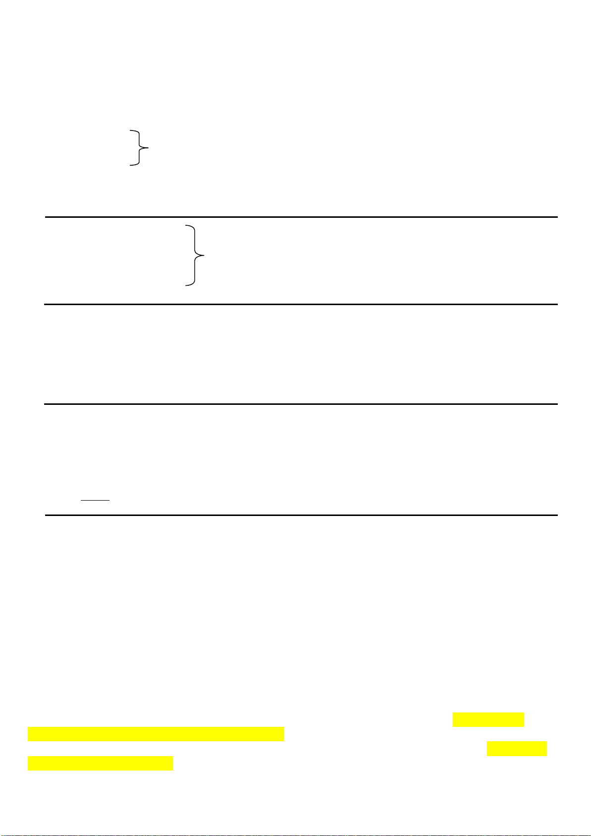
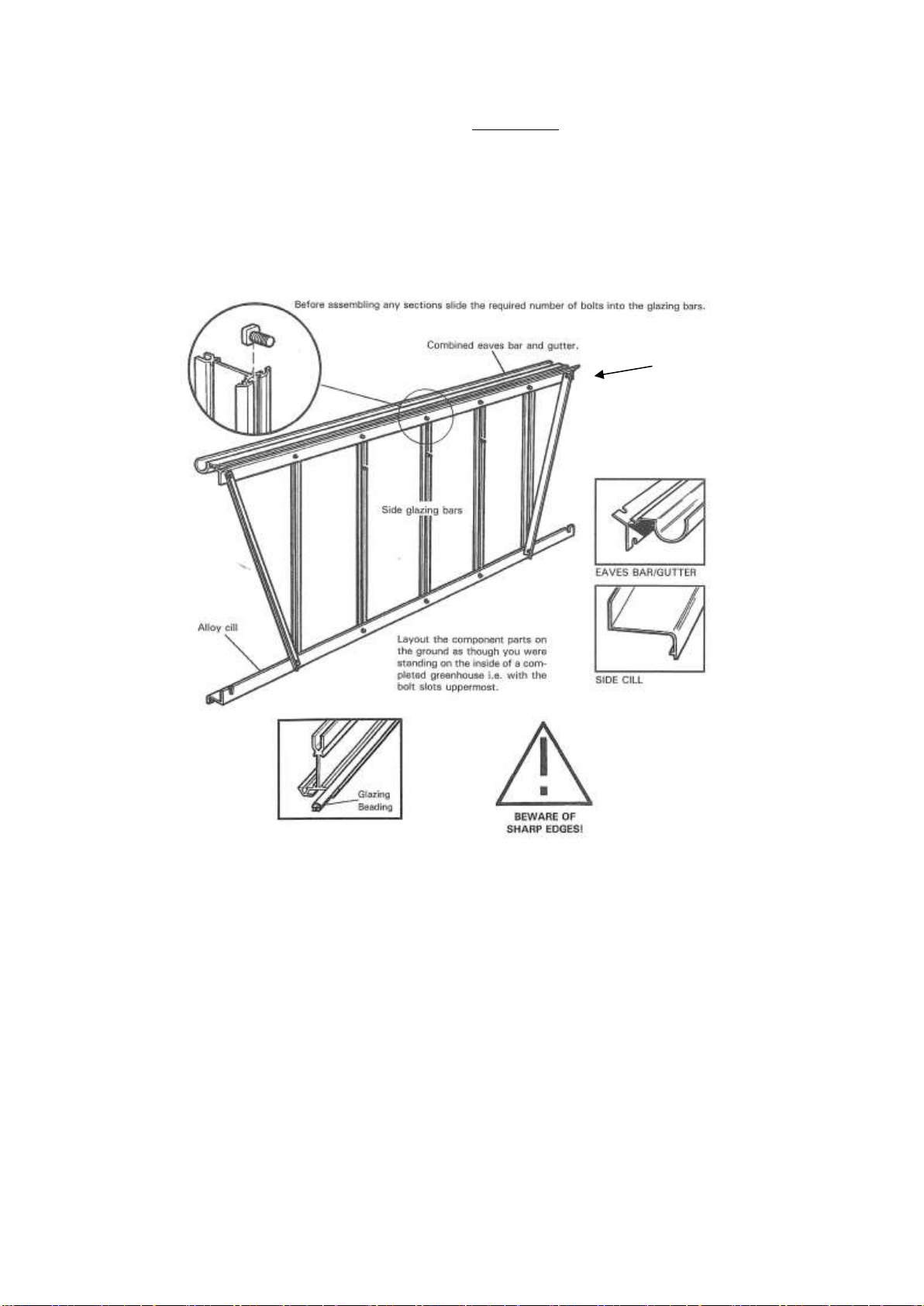
DETAILED ASSEMBLY INSTRUCTIONS
The contents of this carton are divided into the different frame assemblies that collectively make up the complete unit.
It is recommended that each frame assembly is fully completed before moving on to the next.
The frames to be constructed are as follows:
1. SIDE FRAME –Two off.
2. REAR GABLE –One off.
3. DOOR GABLE –One off.
4. ROOF VENT –Two for 2.57m x 3.80m and four for 2.57m x 5.04m.
5. DOOR –One off
6. CLADDING –All, including 20mm square aluminium ‘strongbacks’. Fit the aluminium foil tape to the top edges of each
sheet of polycarbonate before installing
7. Additional parts such as the ridge, roof bars, eaves ties etc. are put on “loose” and are not pre-constructed into an
independent frame.
7
SIDE FRAME ASSEMBLY
PROCEDURE
For the point of this plan we have used a standard 2.57m wide x 3.80m Length as an illustration. Other models will have
different final dimensions or views, but use the same process for assembly.
From the main box you require: Pack of side bars marked “side bars”.
Pack of gutters, angles and cills marked “side”.
From the pack of fittings you need: Nuts and bolts + the Glazing beading.
You need for each frame: 1 gutter/eave, 1 cill, 2 diagonal angles and 5 side bars. Before assembling any of the side frame
section you will need to slide the required number of bolts into the glazing bars. (See drawing). Assemble the side frames as
shown.
1. Slide the glazing beading into each side bar taking care not to stretch the material. Trim off any surplus level with the ends
of the glazing bar.
2. Lay the 9 components on the floor as though you were standing inside the Polycarbhouse i.e. with the gutter and cill facing
downwards and the bolt slot of the glazing bar upwards. (Key point)
3. Slide 3 bolts into each glazing bar, the middle bolt will be used later to attach the cantilever tee bars. Fix the combined
eaves and gutter bars to the glazing bars by pushing the bolt previously inserted through the holes in the lower flange of the
eave and secure with a nut. Ensure that the glazing bar is pushed up under the gutter and is tight up against the inside
shoulder of the eave. (Key Point). Do the same with the rest of the glazing bars.
4. Fix the cill in a similar way to 3 above but start with the middle glazing bars and work outwards.
5. The 2 outer glazing bars have the angle ties bolted to them. Before attaching the nuts, place the tie bar over the bolts so
that they point outwards towards the end of the eaves bar. They must be arranged so that the inside of the angle, in each
case faces towards the middle of the house.
N.B. for the 3.804m model there are 2 angle ties per side, for the 5.040m there are 4 per side: the extra braces are centrally
positioned (diagonally like the 2 end ones) for additional strength.
6. Ensure that the glazing bars are tight up against the cill and inside shoulder of the eave, tighten all nuts. The nuts and bolts
are aluminum and only require one turn with the spanner after first finger tip tightening. (Key Point).
7. Do exactly the same with the other side frame.
WELL DONE! YOU HAVE SUCCESSFULLY COMPLETED THE 2 SIDE FRAMES!
IMPORTANT!!
Must be fitted
as shown in
picture.
8
REAR WALL END ASSEMBLY
1. Starting with the pack of corner bars split the tape holding them together and first identifies the 2 roof bars from the 2
sidebars. The sidebars have one hole and one mitre, both at one end. The other end has no hole and is square cut. The roof
bars have 4 holes in the flange and are mitred at both ends and in addition have a letter “R” written at the apex on the outside
of the bar.
The bars are also handed so you must identify the left and right hand. Standing up, hold one side bar vertically in your left
hand, the other in your right. Rotate the bars so that the 2 bolt slots are facing in towards you, with the mitres at the top
(inside view). Viewed this way the 2 mitres should run down to each other. The roof bars can be handed similarly, keeping the
bolt slots facing inwards and the letter “R” to the top. (With a painted model, the top can be identified by observing the 4
holes in the flange. The two holes nearest the end are at 50mm and 33mm centres. The 50mm end is the top i.e. nearest the
ridge) On the outside you can identify them by ensuring that the “R”s (indicating ridge) are at the top, the mitres will then run
into each other.
2. Slide the glazing beading into the 4 vertical glazing bars and the 4 corner bars, taking care not to stretch the material. Trim off
any surplus level with the end of the bars. N.B. The corner bars have 3 grooves to receive the glazing bead; do not put any in
the middle one. (Key point).
3. Lay out the components of the frame on the ground as though you were standing on the inside i.e. with the bolt slots
uppermost. Ensure that, having correctly identified the roof from the side corner bars, left and right hands (see previous text)
you have the roof bars with the letter “R” (indicating ridge) at the top on the outside, i.e. towards the ground. (Key Point)
4. Slide 2 bolts into each corner bar bolt slots (facing inwards) 1 at the top and 1 at the bottom. Put a nut on and lightly tighten,
leaving them approx. 2” from the end of each bar. These will be used later in the general assembly.
5. Starting at the apex (2 corner bars opposite each other marked “R”) slide 1 bolt into the other bolt slot i.e. the one that is facing
upwards and is set at 90to the other –4 above. (Key Point)
For the construction of this frame you require from the main box:
1 pack of corner bars marked “corner bars”
1 rear end pack marked “rear end”
1 rear end cill marked “rear end”
1 rear end horizontal brace marked “rear end”.
From the pack of fittings you need:
nuts and bolts
Glazing beading and gusset plates –1 large (ridge plate) and 2
small (eave plates).
These plates are not in the pack of fittings but are taped up with the
casement stays elsewhere in the box.
9
G
R
GR = GLAZING RUBBER
GR
GR
GR
GR
GR
GR
NO Glazing
Bead
10
6. Place the Ridge gusset plate (larger of the 2 types) over the bolt, slide the plate left or right until the slotted hole in the plate
lines up with the locating hole in the flange nearest to the end of the corner bar. Put nuts on both bolts i.e. flange and plate,
fingertip tighten only. (Key point)
7. Do exactly the same with the other roof corner bar ensuring that the two bars are pressed tight up together behind the Ridge
gusset plate.
8. Now moving to the eave gusset assembly, slide one bolt into the other bolt slot (the one that is facing upwards and is at 90to
4 above). Place the eave gusset plate (smaller of the 2 types) onto the bolt and move it left or right until the next hole in the
plate lines up with the locating hole in the top on the side corner bar. Place a bolt through the hole and put a nut on fingertip
tight only. (Key point). At this stage do not put a nut on the first bolt.
9. Do the same with the other part of the same eave gusset plate, ensuring that both corner bars are tight up against each other
behind the eave plate.
10. Repeat steps 8 and 9 at the other corner with another eave gusset plate.
11. Attach the bottom cill, marked “rear end” in the box, to the left and right hand side corner bars by inserting a bolt into the
facing bolt slot. Line the bolts up with the 2 slotted holes at the end of the cill, put nuts on and tighten up ensuring that the
corner bars are pushing right down into the angle of the cill. (Key Point).
12. You can now attach the 4 vertical glazing bars to the bottom cill in a similar manner to 11 above, the two longer bars to the
middle holes, and the shorter ones to the outer holes. Before attaching the nuts to the longer bars place the diagonal angles
onto the bottom bolt and put a nut on fingertip tight only. Attach the other end of the angle brace to the bottom bolt of the
eave gusset plate, put on the nut and finger tip tighten. (Key Point). Do the same with the other diagonal brace.
13. Moving to the top of the greenhouse, insert 3 bolts into the shorter two glazing bars and 2 bolts into the longer two glazing
bars.
14. Now you can attach the long angle horizontal brace marked “rear end” in the box to the top bolts of the eave gusset plates.
The angle should be facing upwards, put the nuts on and fingertip tighten.
15. You can now attach the 4 vertical glazing bars to the roof/corner bars. Slide the last bolt in each bar you inserted in 13 above
to the end of each bar and insert them through the holes in the flange of the roof corner bar, place the nuts on and finger tip
tighten.
16. Attach the diagonal angles to the 2 shorter glazing bars. Slide the second bolt previously inserted in 13 above to the middle of
the bare and line it up with the hole in the diagonal brace, put the nuts on finger tip tight. (Key Point)
17. Now attach the horizontal brace to the 4 upright glazing bars utilizing the final bolts you inserted in 13 above. Put the nuts on
finger tip tight. (Key Point).
18. The rear end is now almost complete. Before tightening all nuts check the corners to ensure they are tightly up against each
other and that all the vertical bars are tight up against the angle of the rear end cill and corner bars. Tighten all nuts, the rear
end if now complete
Detail of Eave Assembly