Fluke 15B User manual

PN 4372130
February 2014
© 2014 Fluke Corporation. All rights reserved. Specifications are subject to change without notice.
All product names are trademarks of their respective companies.
15B+/17B+/18B+
Digital Multimeters

LIMITED WARRANTY AND LIMITATION OF LIABILITY
This Fluke product will be free from defects in material and workmanship for one year from the date of purchase. This
warranty does not cover fuses, disposable batteries, or damage from accident, neglect, misuse, alteration, contamination, or
abnormal conditions of operation or handling. Resellers are not authorized to extend any other warranty on Fluke’s behalf.
To obtain service during the warranty period, contact your nearest Fluke authorized service center to obtain return
authorization information, then send the product to that Service Center with a description of the problem.
THIS WARRANTY IS YOUR ONLY REMEDY. NO OTHER WARRANTIES, SUCH AS FITNESS FOR A PARTICULAR
PURPOSE, ARE EXPRESSED OR IMPLIED. FLUKE IS NOT LIABLE FOR ANY SPECIAL, INDIRECT, INCIDENTAL OR
CONSEQUENTIAL DAMAGES OR LOSSES, ARISING FROM ANY CAUSE OR THEORY. Since some states or countries
do not allow the exclusion or limitation of an implied warranty or of incidental or consequential damages, this limitation of
liability may not apply to you.
Fluke Corporation
P.O. Box 9090
Everett, WA 98206-9090
U.S.A.
Fluke Europe B.V.
P.O. Box 1186
5602 BD Eindhoven
The Netherlands
11/99
Service Centers:
Fluke Beijing Service Center
Room 401 SCITEC Tower
Jianguomenwai Dajie
Beijing 100004, PRC
Tel: 400-810-3435
Shanghai Shilu Instrument Co., Ltd.
#139, Lane 2638, Hongmei Road (South)
Shanghai 201108
Standard Number: Q/SXAV 1-2002

i
Table of Contents
Title Page
Introduction .................................................................................................................... 1
Safety Information .......................................................................................................... 1
Instrument Overview ...................................................................................................... 5
Terminals................................................................................................................... 5
Display....................................................................................................................... 6
Auto Power Off............................................................................................................... 7
Auto Backlight Off .......................................................................................................... 7
Measurements ............................................................................................................... 7
Manual and Auto Range Selection ............................................................................ 7
Data Hold .................................................................................................................. 8
Relative Measurements (17B+ only) ......................................................................... 8
MIN MAX Mode (17B+ Only) ..................................................................................... 8
Measure AC and DC Voltage .................................................................................... 9
Measure AC or DC Current ....................................................................................... 10
Measure Resistance.................................................................................................. 11

15B+/17B+/18B+
Users Manual
ii
Test for Continuity..................................................................................................... 11
Test Diodes............................................................................................................... 12
Measure Capacitance ............................................................................................... 12
Measure Temperature (17B+ only) ........................................................................... 12
Measure Frequency and Duty Cycle (17B+/18B+ Only) ........................................... 13
Test LEDs (18B+ Only)............................................................................................. 13
Maintenance .................................................................................................................. 14
General Maintenance................................................................................................ 15
Test Fuses ................................................................................................................ 15
Replace Batteries and Fuses.................................................................................... 16
Service and Parts .......................................................................................................... 17
General Specifications................................................................................................... 18
Accuracy Specifications................................................................................................. 19
AC and DC Voltage................................................................................................... 19
AC and DC Current................................................................................................... 20
Diode Test, Temperature, Resistance, Capacitance, Frequency, and Duty Cycle ... 21
LED Test and Continuity Threshold .......................................................................... 22
Input Characteristics ................................................................................................. 23

1
Introduction
The Fluke 15B+/17B+/18B+ Multimeters (the Product) are
4000 count instruments. The Product is battery powered
with a digital display.
Except where noted, the descriptions and instructions in
this Users Manual apply to all of 15B+/17B+/18B+.
Unless otherwise identified, all illustrations show the
17B+.
How to Contact Fluke
To contact Fluke, call one of the following telephone
numbers:
•Technical Support USA: 1-800-44-FLUKE (1-800-
443-5853)
•Calibration/Repair USA: 1-888-99-FLUKE (1-888-
993-5853)
•Canada: 1-800-36-FLUKE (1-800-363-5853)
•Europe: +31 402-675-200
•Japan: +81-03-6714-3114
•Singapore: +65-6799-5566
•Mainland China: +86-400-810-3435
•Anywhere in the world: +1-425-446-5500
Or, visit Fluke's website at www.fluke.com.
To register your product, visit http://register.fluke.com.
To see, print, or download the latest manual supplement,
visit http://us.fluke.com/usen/support/manuals.

15B+/17B+/18B+
Users Manual
2
Safety Information
A Warning identifies conditions and procedures that are
dangerous to the user. A Caution identifies conditions
and procedures that could cause damage to the Product
or the equipment under test.
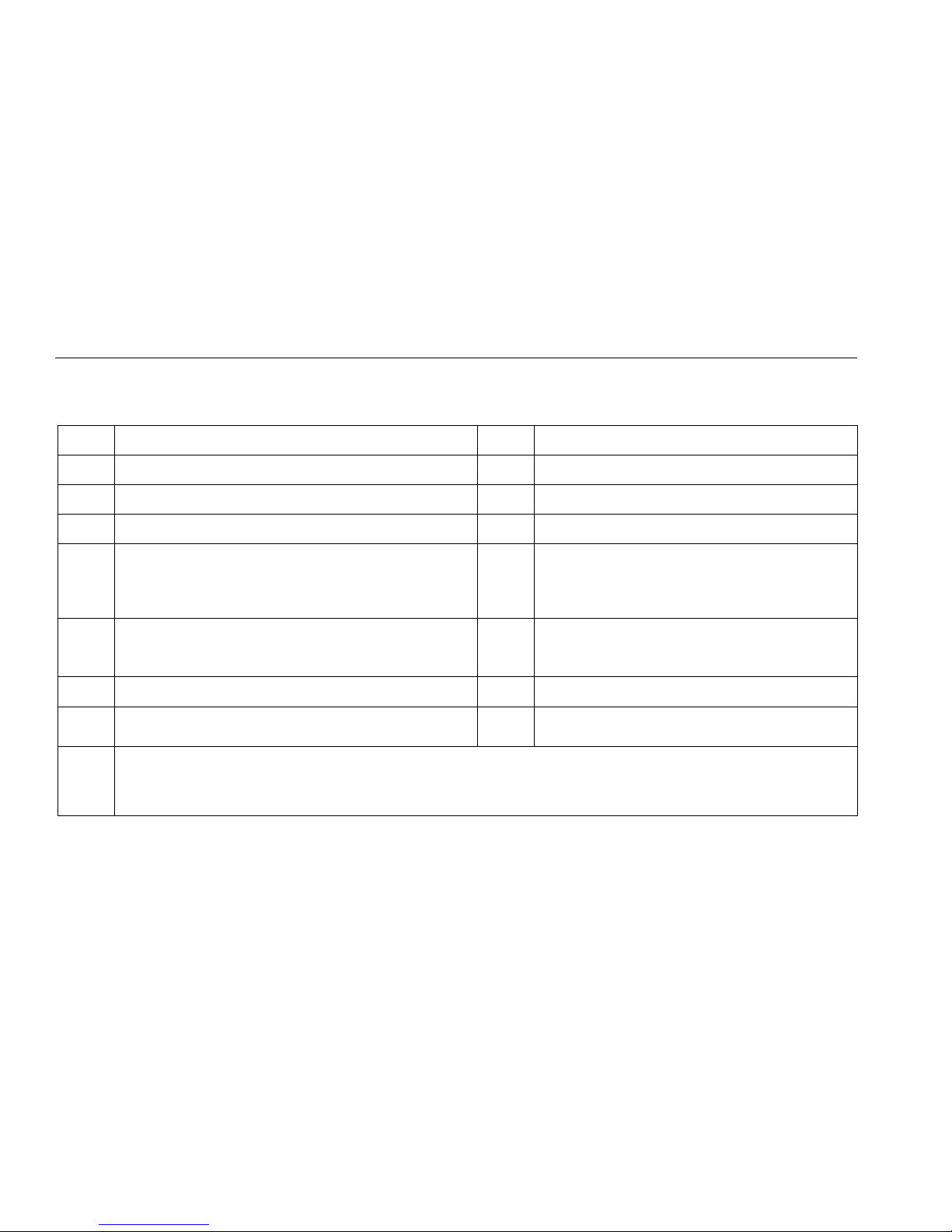
International electrical symbols used on the Product and in
this manual are explained in Table 1.
Review the safety information and comply with the safe
working practices.
Warning
To prevent possible electrical shock, fire, or
personal injury:
•Carefully read all instructions.
•Read all safety information before you use the
Product.
•Use the Product only as specified, or the
protection supplied by the Product can be
compromised.
•Do not use the Product around explosive gas,
vapor, or in damp or wet environments.
•Examine the case before you use the Product.
Look for cracks or missing plastic. Carefully
look at the insulation around the terminals.
•Do not use the Product if it is damaged.
•Do not use the Product if it operates
incorrectly.
•Comply with local and national safety codes.
Use personal protective equipment (approved
rubber gloves, face protection, and flame-
resistant clothes) to prevent shock and arc
blast injury where hazardous live conductors
are exposed.
•Use only correct measurement category (CAT),
voltage, and amperage rated probes, test leads,
and adapters for the measurement.
•Do not use test probes in CAT III
environments without the protective cap
installed. The protective cap decreases the
exposed probe metal to <4mm. This
decreases the possibility of arc flash from
short circuits.
•Measure a known voltage first to make sure
that the Product operates correctly.
•Limit operation to the specified measurement
category, voltage, or amperage ratings.

Digital Multimeters
Safety Information
3
•Do not apply more than the rated voltage,
between the terminals or between each
terminal and earth ground.
•Do not touch voltages > 30 V ac rms, 42 V ac
peak, or 60 V dc.
•Do not use test leads if they are damaged.
Examine the test leads for damaged insulation
and measure a known voltage.
•Connect the common test lead before the live
test lead and remove the live test lead before
the common test lead.
•Keep fingers behind the finger guards on the
probes.
•Remove all probes, test leads, and accessories
before the battery door is opened.
•Do not exceed the Measurement Category
(CAT) rating of the lowest rated individual
component of a Product, probe, or accessory.
•Remove the batteries if the Product is not used
for an extended period of time, or if stored in
temperatures above 50 °C. If the batteries are
not removed, battery leakage can damage the
Product.
•Replace the batteries when the low battery
indicator () shows to prevent incorrect
measurements.
•Use the correct terminals, function, and range
for measurements.
•Disconnect all test leads from any hazardous
voltage before switching to the LED TEST
function. Refer to the LED TEST section for
proper measurement technique and
interpretation of results (for 18B+ only).

15B+/17B+/18B+
Users Manual
4
Table 1. International Electrical Symbols
AC (Alternating Current) Earth Ground
DC (Direct Current) Fuse
Diode Capacitance
Hazardous voltage. Risk of electrical shock. Battery
Risk of Danger. Important information. See Manual.
CAT II
MEASUREMENT CATEGORY II is applicable to
test and measuring circuits connected directly to
utilization points (socket outlets and similar points)
of the low voltage MAINS installation.
CAT III
MEASUREMENT CATEGORY III is applicable to test and
measuring circuits connected to the distribution part of the
building’s low-voltage MAINS installation.
CAT IV
MEASUREMENT CATEGORY IV is applicable to
test and measuring circuits connected at the source
of the building’s low voltage MAINS installation.
Conforms to European Union directives. Conforms to relevant North American Safety
Standards.
Conforms to relevant South Korean EMC Standards Conforms to relevant Australian Standards.
This product complies with the WEEE Directive (2002/96/EC) marking requirements. The affixed label indicates that you must
not discard this electrical/electronic product in domestic household waste. Product Category: With reference to the equipment
types in the WEEE Directive Annex I, this product is classed as category 9 "Monitoring and Control Instrumentation" product.
Do not dispose of this product as unsorted municipal waste. Go to Fluke’s website for recycling information.

Digital Multimeters
Instrument Overview
5
Instrument Overview
Terminals
1
23
4
hpq01.eps
Item Description
Input terminal for ac and dc current measurement to 10 A and frequency (17B+/18B+) measurements.
Input terminal for ac and dc microamp and milliamp measurements to 400 mA and frequency (17B+/18B+)
measurements.
Common (return) terminal for all measurements.
Input terminal for voltage, resistance, continuity, diode, capacitance, frequency (17B+/18B+), duty cycle
(17B+/18B+), temperature (17B+ only), and LED test (18B+ only) measurements.

15B+/17B+/18B+
Users Manual
6
Display
2
1
16
3456 7 8
9
10
11
12
13
14
15
hpq02.eps
Item Description Item Description
Relative measurement is enabled (17B+ only). Duty cycle is selected (17B+/18B+).
High voltage Resistance or Frequency (17B+/18B+) is selected.
Continuity is selected. Farads for capacitance.
Display Hold is enabled. millivolts or volts
MIN or MAX mode is enabled (17B+ only). dc or ac voltage or current
LED test is enabled (18B+ only). microamp, milliamp, or amp
Fahrenheit or Celsius is selected (17B+ only). Auto range mode or Manual range mode is enabled.
Diode test is selected. Battery is low and should be replaced.

Digital Multimeters
Auto Power Off
7
Auto Power Off
The Product automatically powers off after 20 minutes of
inactivity.
To restart the Product, turn the rotary switch back to the
OFF position and then to a necessary position.
To disable the Auto Power Off function, hold down
when turning on the Product, until PoFF shows on the
display.
Note
When you disable the Auto Power Off function,
LoFF also shows on the display. The Auto
Backlight Off function is also disabled.
Auto Backlight Off
The backlight automatically turns off after 2 minutes of
inactivity.
To disable the Auto Backlight Off function, hold down
when turning on the Product, until LoFF shows on the
display.
Measurements
Warning
To prevent possible electrical shock, fire, or
personal injury, disconnect power and
discharge all high-voltage capacitors before
you measure resistance, continuity,
capacitance, or a diode junction.
Manual and Auto Range Selection
The Product has both manual and auto range options. In
the auto range mode, the Product selects the best range
for the input detected. This allows you to switch test points
without having to reset the range. You can override auto
ranging by selecting the range manually.
By default, the Product uses the auto range mode in
measurement functions that have more than one range
and shows Auto Range on the display.
To enter the manual range mode, push .
Note
Each push of increments the range. When
the highest range is reached, the Meter wraps to
the lowest range.
To exit the manual range mode, push and hold for two
seconds.

15B+/17B+/18B+
Users Manual
8
Data Hold
Warning
To prevent possible electrical shock, fire or
personal injury, do not use the HOLD function
to measure unknown potentials. When HOLD
is turned on, the display does not change
when a different potential is measured.
To hold the present reading, push . Push again
to resume normal operation.
Relative Measurements (17B+ only)
The Product allows relative measurements for all functions
except frequency, resistance, continuity, duty cycle, and
diode.
To do relative measurements:
1. With the Product in the desired function, touch the
test leads to the circuit on which you want future
measurements to be based.
2. Push to store the measured reading as the
reference value and activate the relative
measurement mode.
The difference between the reference value and
subsequent reading shows on the display.
3. Push for to return to normal operation.
MIN MAX Mode (17B+ Only)
To set the Product to MIN MAX mode (available for all
functions except resistance, capacitance, frequency, duty
cycle, and diode):
1. Push once to set the Product to MAX mode.
2. Push again to set the Product to MIN mode.
3. Push for 2 seconds to return to normal operation.

Digital Multimeters
Measurements
9
Measure AC and DC Voltage
To measure ac and dc voltage:
1. Turn the rotary switch to , , or to choose ac or
dc.
2. Push to toggle between mVac or mVdc voltage
measurement.
3. Connect the red test lead to the terminal and the
black test lead to the COM terminal.
4. Touch the probes to the correct test points of the circuit
to measure the voltage, as shown in Figure 1.
5. Read the measured voltage on the display.
V ac V dc mV ac/dc
hpq03.eps
Figure 1. Measure AC and DC Voltage

15B+/17B+/18B+
Users Manual
10
Measure AC or DC Current
Warning
To prevent possible electrical shock, fire, or
personal injury, remove circuit power before
you connect the Product in the circuit when
you measure current. Connect the Product in
series with the circuit.
To measure ac or dc current:
1. Turn the rotary switch to , , or .
2. Push to toggle between ac or dc current
measurement.
3. Connect the red test lead to the A or mA μA terminal
based on the current to be measured and connect the
black test lead to the COM terminal. See Figure 2.
4. Break the circuit path to be measured. Then connect
the test leads across the break and apply power.
5. Read the measured current on the display.
AC
hpq04.eps
Figure 2. Measure AC and DC Current

Digital Multimeters
Measurements
11
Measure Resistance
To measure resistance:
1. Turn the rotary switch to . Make sure power is
disconnected from the circuit to be measured.
2. Connect the red test lead to the terminal and
the black test lead to the COM terminal, as shown
in Figure 3.
3. Measure the resistance by touching the probes to
the desired test points of the circuit.
4. Read the measured resistance on the display.
Test for Continuity
To test for continuity:
With the resistance mode selected, push once to
activate the continuity beeper. If the resistance is <70 Ω,
the beeper will sound continuously, designating a short
circuit. See Figure 3.
<70
hpq05.eps
Figure 3. Measure Resistance/Continuity

15B+/17B+/18B+
Users Manual
12
Test Diodes
Caution
To prevent possible damage to the Product or
to the equipment under test, disconnect
circuit power and discharge all high-voltage
capacitors before you test diodes.
1. Turn the rotary switch to .
2. Push twice to activate Diode Test.
3. Connect the red test lead to the terminal and the
black test lead to the COM terminal.
4. Connect the red probe to the anode side and the black
test lead to the cathode side of the diode being tested.
5. Read the forward bias voltage value on the display.
6. If the polarity of the test leads is reversed with diode
polarity, the display reading shows . This can be
used to distinguish the anode and cathode sides of a
diode.
Measure Capacitance
Caution
To prevent damage to the Product,
disconnect circuit power and discharge all
high-voltage capacitors before you measure
capacitance.
1. Turn the rotary switch to .
2. Connect the red test lead to the terminal and the
black test lead to the COM terminal.
3. Touch the probes to the capacitor leads.
4. After allowing the reading to stabilize (up to 18
seconds), read the capacitance value on the display.
Measure Temperature (17B+ only)
To measure temperature:
1. Turn the rotary switch to .
2. Plug the thermocouple into the and COM
terminals of the Product.
Ensure that the thermocouple plug marked with “+” is
inserted into the terminal on the Product.
3. Read the temperature on the display.
4. Push to switch between °C and °F.

Digital Multimeters
Measurements
13
Measure Frequency and Duty Cycle (17B+/18B+
Only)
The Product can measure frequency or duty cycle while
making either a voltage or a current measurement. Push
to change the Product to frequency or duty cycle.
1. When the Product is in the required function (ac
voltage or ac current), push .
2. Read the frequency of the signal on the display.
3. To make a duty cycle measurement, push again.
4. Read the percent of duty cycle on the display.
Test LEDs (18B+ Only)
Caution
To prevent possible damage to the Product or
to the equipment under test, disconnect all
test leads from any hazardous voltage before
you switch to the LED TEST function.
The Product tests Light Emitting Diodes (LEDs) either
through the LED test socket on the Meter or through the
test leads.
Note
Do not use the LED Test mode to do LED aging
tests.
To test an LED mounted in the test socket:
1. Turn the rotary switch to LED TEST.
2. Place the leads of the LED into the holes of the LED
test socket on the front of the Meter as shown in
Figure 4.

15B+/17B+/18B+
Users Manual
14
If the LED is good, the Product will illuminate the LED
under test and an anode indicator will illuminate to indicate
the (+) pin. If the LED is broken, the LED will not illuminate
and neither of the anode indicators will illuminate. If the
LED is a short circuit, the LED will not illuminate, and both
anode indicators will illuminate.
LED Anode Indicators
hpq07.eps
Figure 4. LED Test Sockets
Maintenance
Beyond replacing batteries and fuses, do not attempt to
repair or service the Product unless you are qualified to do
so and have the relevant calibration, performance test,
and service instructions. The recommended calibration
cycle is 12 months.
Warning
To prevent possible electrical shock, fire, or
personal injury:
•Remove the input signals before you clean the
Product.
•Use only specified replacement fuses.
•Have an approved technician repair the Product.
For safe operation and maintenance of the
Product:
•Repair the Product before use if the batteries
leak.
•Batteries contain hazardous chemicals that can
cause burns or explode. If exposure to chemicals
occurs, clean with water and get medical aid.

Digital Multimeters
Maintenance
15
General Maintenance
Periodically wipe the case with a damp cloth and mild
detergent. Do not use abrasives or solvents. Dirt or
moisture in the terminals can affect readings.
To clean the terminals:
1. Turn the Product off and remove the test leads.
2. Shake out any dirt that may be in the terminals.
3. Soak a new swab with isopropyl alcohol and work
around the inside of each input terminal.
Test Fuses
Warning
To prevent electric shock or injury, remove
the test leads and any input signals before
replacing the fuses.
1. Turn the rotary switch to .
2. Plug a test lead into the terminal and touch the
probe to the Aor mA μAterminal.
•A good Aterminal fuse reads approximately 0.1 Ω.
A good mA/μAterminal fuse reads less than 10 kΩ.
•If the display reads , replace the fuse and test
again.
•If the display shows any other value, have the
Product serviced. See “Service and Parts”.

15B+/17B+/18B+
Users Manual
16
Replace Batteries and Fuses
Warning
To prevent false readings, which could lead to
possible electric shock or personal injury,
replace the batteries as soon as the battery
indicator () appears.
To prevent damage or injury, install ONLY
replacement fuses with the specified
amperage, voltage, and interrupt ratings.
Disconnect test leads before opening the
case or the battery door.
To replace the batteries or the fuses, see Figure 5.
B1
F1
F2
hpq06.eps
Figure 5. Replace Batteries and Fuses
Other manuals for 15B
3
This manual suits for next models
2
Table of contents
Other Fluke Multimeter manuals

Fluke
Fluke 8842A User manual

Fluke
Fluke 8508A User manual

Fluke
Fluke 116 User manual

Fluke
Fluke 175 User manual

Fluke
Fluke 8012A User manual

Fluke
Fluke 8588A User manual

Fluke
Fluke Biomedical MPS450 Operators User manual

Fluke
Fluke 287 User manual

Fluke
Fluke 77 Series III User manual

Fluke
Fluke CNX C3000 User manual

Fluke
Fluke 233 User manual

Fluke
Fluke 8050A User manual

Fluke
Fluke 707 Installation and operating instructions

Fluke
Fluke LinkRunner Duo User manual

Fluke
Fluke 233 User manual

Fluke
Fluke 8600A User manual

Fluke
Fluke 365 Use and care manual

Fluke
Fluke 8845A User manual

Fluke
Fluke 1508 User manual

Fluke
Fluke 8024B User manual