Hioki dt4212 User manual

Instruction Manual
November 2013 Revised edition 1
使用说明书
DT4212
DIGITAL MULTIMETER
数字万用表
DT4211
2013年11月 修订一版
DT4211A981-01 13-11H


i
Contents
Introduction.........................................................................1
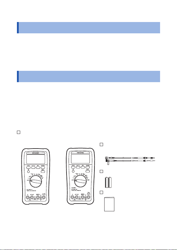
Verifying Package Contents..............................................1
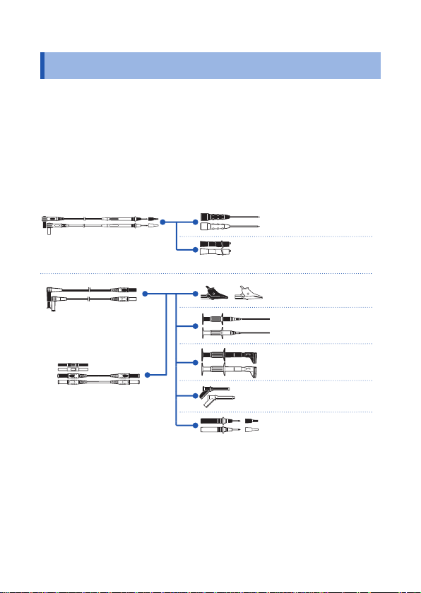
Options (sold separately) ..................................................2
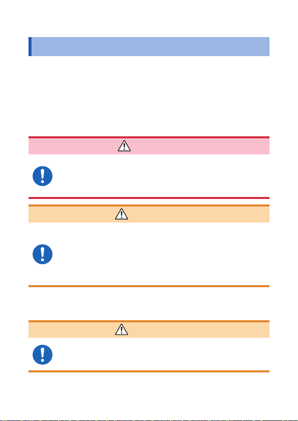
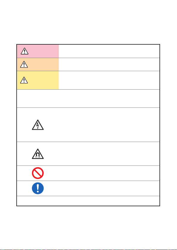
Safety Notes........................................................................4
Usage Notes........................................................................8
1 Overview 15
1.1 Overview and Features.................................15
1.2 Parts Names and Functions.........................16
1.3 Display ...........................................................21
2 Preparation for Measurements 23
2.1 Measurement Workflow................................23
2.2 Inserting/Replacing Batteries ......................24
2.3 Using Test Leads...........................................26
3 Performing Measurements 29
3.1 Inspection Before Use ..................................29
3.2 Measuring Voltage.........................................33
Measuring AC voltage...............................................33
Measuring DC voltage..............................................34
3.3 Measuring Resistance ..................................35
3.4 Measuring Diode ...........................................36
3.5 Checking Continuity .....................................37
3.6 Measuring Electrostatic Capacities.............38
3.7 Measuring Frequencies................................39
3.8 Measuring Duty Ratio ...................................40
3.9 Measuring Current ........................................41
Measuring DC/AC.....................................................41
Ind.Appx.
7
6
5
4
3
2
1

ii
Contents
3.10 Measuring Temperatures (DT4212)..............43
4 Using Instrument Conveniently 45
4.1 Selecting the Measurement Range..............45
Measuring with the auto range .................................45
Measuring with the manual range.............................45
4.2 Retaining the Measured Value .....................46
Retaining the measured value (HOLD).....................46
4.3 Checking the Relative Value/Performing
Zero Adjustment............................................47
Checking the relative value (REL)............................47
Performing zero adjustment......................................48
4.4 Turning On the Backlight..............................49
4.5 Using the Auto Power Save (APS)...............49
5 Specifications 51
5.1 General Specifications .................................51
5.2 Electrical Characteristics.............................53
5.3 Accuracy Table..............................................55
6 Maintenance and Service 63
6.1 RepairInspectionand Cleaning.................63
6.2 Troubleshooting............................................64
6.3 Replacing Fuses............................................67
Appendix Appx.1
Appx. 1 RMS and Average .............................Appx.1

1
Introduction
Introduction
Thank you for purchasing the HIOKI DT4211 (Average value
measurement model), DT4212 (True RMS measurement model)
Digital Multimeter.
To obtain maximum performance from the product, please read this
manual first, and keep it handy for future reference.
Verifying Package Contents
When you receive the instrument, inspect it carefully to ensure that
no damage occurred during shipping.
In particular, check the accessories, panel switches, and connectors.
If damage is evident, or if it fails to operate according to the
specifications, contact your authorized Hioki distributor or reseller.
Check the package contents as follows.
DT4211 (Average value measurement model) or DT4212 (True RMS
measurement model)
DT4211
(Average value
measurement model)
DT4212
(True RMS
measurement model)
The holster has been attached.
L9206 Test Lead
(p. 27)
R6P manganese battery × 2
Instruction Manual
1
Ind.Appx.
7
6
5
4
3
2

2
Options (sold separately)
The following options are available for the instrument. Contact your
authorized Hioki distributor or reseller when ordering.
Connecting cables
*1: CAT IV 600 V/CAT III 1000 V/CAT II 1000 V
*2: CAT IV 600 V/CAT III 1000 V
*3: CAT III 1000 V *5: CAT III 300 V/CAT II 600 V
*4: CAT III 600 V *6: AC33 V /DC70 V
L4933*6
Contact Pin Set
L4934*5
Small Alligator Clip Set
L4935*2
Alligator Clip Set
9243*3
Grabber Clip
L4936*4
Bus Bar Clip Set
L4937*3
Magnetic Adapter Set
L4932*1
Test Pin Set
L9206*1
Test Lead
L4930*2
Connection Cable Set
(Length: 1.2 m)
L4931*2
Extension Cable Set
(Length: 1.5 m, with the
coupling connector)

3
Options (sold separately)
Temperature measurement (Only the DT4212 (True RMS
measurement model))
DT4910 Thermocouples (K) (p. 43)
•Temperature measuring junction: Exposed type (welding)
•Sensor length: Approx. 800 mm
•
Operating temperature: -40°C to 260°C (temperature
measuring part), -15°C to 55°C (connector)
•
Allowable tolerance: ±2.5°C
Carrying Case
C0201 Carrying Case
The instrument, test leads, instruction manual, and others
can be stored in the case.
C0202 Carrying Case
The instrument, test leads, instruction manual, and others
can be stored in the case.
Z5004 Magnetic Strap
Attach this strap to the instrument and secure it on the
wall surface such as a metal plate for use.
Handling the strap (p. 11)
For the detailed procedure of the C0201 Carrying Case and Z5004 Magnetic
Strap, refer to our Website.
1
Ind.Appx.
7
6
5
4
3
2

4
Safety Notes
Safety Notes
This instrument is designed to conform to IEC 61010 Safety
Standards, and has been thoroughly tested for safety prior to
shipment. However, using the instrument in a way not described in
this manual may negate the provided safety features.
Before using the instrument, be certain to carefully read the
following safety notes.
DANGER
Mishandling during use could result in injury or death,
as well as damage to the instrument. Be certain that
you understand the instructions and precautions in
the manual before use.
WARNING
With regard to the electricity supply, there are risks
of electric shock, heat generation, fire, and arc
discharge due to short circuits. If persons unfamiliar
with electricity measuring instruments are to use
the instrument, another person familiar with such
instruments must supervise operations.
Protective gear
WARNING
To avoid electric shock when measuring live lines,
wear appropriate protective gear, such as insulated
rubber gloves, boots and a safety helmet.

5
Safety Notes
Notation
In this manual, the risk seriousness and the hazard levels are
classified as follows.
DANGER Indicates an imminently hazardous situation that will
result in death or serious injury to the operator.
WARNING Indicates a potentially hazardous situation that may
result in death or serious injury to the operator.
CAUTION Indicates a potentially hazardous situation that may
result in minor or moderate injury to the operator or
damage to the instrument or malfunction.
IMPORTANT Indicates information related to the operation of the
instrument or maintenance tasks with which the
operators must be fully familiar.
Indicates a high voltage hazard.
If a particular safety check is not performed or the
instrument is mishandled, this may give rise to a
hazardous situation; the operator may receive an
electric shock, may get burnt or may even be fatally
injured.
Indicates a strong magnetic-field hazard.
The effects of the magnetic force can cause
abnormal operation of heart pacemakers and/or
medical electronics.
Indicates prohibited actions.
Indicates the action which must be performed.
* Additional information is presented below.
1
Ind.Appx.
7
6
5
4
3
2

6
Safety Notes
Symbols affixed to the instrument
Indicates cautions and hazards. When the symbol is printed on
the instrument, refer to a corresponding topic in the Instruction
Manual.
Indicates that dangerous voltage may be present at this terminal.
Indicates a double-insulated device.
Indicates a fuse.
Indicates a grounding terminal.
Indicates DC (Direct Current).
Indicates AC (Alternating Current).
Indicates DC (Direct Current) or AC (Alternating Current).
Symbols for various standards
Indicates the Waste Electrical and Electronic Equipment
Directive (WEEE Directive) in EU member states.
Indicates that the instrument conforms to regulations set out by
the EC Directive.
Accuracy
We define measurement tolerances in terms of rdg. (reading) and
dgt. (digit) values, with the following meanings:
rdg. (Reading or displayed value)
The value currently being measured and indicated on the
measuring instrument.
dgt.
(Resolution)
The smallest displayable unit on a digital measuring instrument,
i.e., the input value that causes the digital display to show a “1”
as the least-significant digit.

7
Safety Notes
Measurement categories
To ensure safe operation of measuring instruments, IEC 61010
establishes safety standards for various electrical environments,
categorized as CAT II to CAT IV, and called measurement categories.
DANGER
•Using a measuring instrument in an environment
designated with a higher-numbered category than
that for which the instrument is rated could result in
a severe accident, and must be carefully avoided.
•Using a measuring instrument without categories in
an environment designated with the CAT II to CAT
IV category could result in a severe accident, and
must be carefully avoided.
This instrument conforms to the safety requirements for CAT II 1000 V, CAT III
600 V measuring instruments.
CAT II: When directly measuring the electrical outlet receptacles of
the primary electrical circuits in equipment connected to an
AC electrical outlet by a power cord (portable tools, household
appliances, etc.)
CAT III: When measuring the primary electrical circuits of heavy equipment
(fixed installations) connected directly to the distribution panel,
and feeders from the distribution panel to outlets
CAT IV: When measuring the circuit from the service drop to the service
entrance, and to the power meter and primary overcurrent
protection device (distribution panel)
T Outlet
CAT II
Internal wiring
Distribution panel
Service entrance
Service drop
CAT IV
Power meter
CAT III
Fixed installation
See: “2.3 Using Test Leads” (p. 26)
1
Ind.Appx.
7
6
5
4
3
2

8
Usage Notes
Usage Notes
Follow these precautions to ensure safe operation and to obtain the
full benefits of the various functions.
DANGER
If the test lead or the instrument is damaged, there is
a risk of electric shock. Before using the instrument,
perform the following inspection.
•Before using the instrument, check that the coating of
the test leads are neither ripped nor torn and that no
metal parts are exposed. Using the instrument under
such conditions could result in electrocution. Replace
the test leads with those specified by our company.
•
To avoid electric shock, check that the white or
red portion (insulated layer) within the cable is not
exposed. Do not use the cable if its internal colored
portion is exposed.
•Before using the instrument the first time, verify that it
operates normally to ensure that no damage occurred
during storage or shipping. If you find any damage,
contact your authorized Hioki distributor or reseller.

9
Usage Notes
Installation
Installing the instrument in inappropriate locations may cause a
malfunction of instrument or may give rise to an accident. Avoid the
following locations.
For details on the operating temperature and humidity, see the
specifications. (p. 51)
CAUTION
•Exposed to direct sunlight or high temperature
•Exposed to corrosive or combustible gases
•Exposed to water, oil, chemicals, or solvents
•Exposed to high humidity or condensation
•Exposed to a strong electromagnetic field or electrostatic
charge
•Exposed to high quantities of dust particles
•Near induction heating systems (such as high-frequency
induction heating systems and IH cooking equipment)
•Susceptible to vibration
•
An unstable table or inclined surface
Using the instrument with the stand
CAUTION
•Do not position the instrument on an
unstable table or inclined surface.
•When the instrument is set on the
stand, do not apply a strong force
above. Doing so may damage the
stand.
1
Ind.Appx.
7
6
5
4
3
2

10
Usage Notes
Handling the cables
WARNING
To prevent electric shock, when measuring the
voltage of a power line use a test lead that satisfies
the following criteria:
•Conforms to safety standards IEC61010 or EN61010
•Of measurement category II or III
•Its rated voltage is higher than the voltage to be
measured
All of the optional test leads for this instrument
conform to the safety standard EN61010. Use a test
lead in accordance with its defined measurement
category and rated voltage.
CAUTION
•Avoid stepping on or pinching the cable, which could
damage the cable insulation.
•To avoid damaging the cables, do not bend or pull the
leads and the probe bases.
The ends of the test leads are sharp. Be careful to avoid
injury.
For the test leads supplied with the instrument or the options to be connected
to the instrument, see the following information.
Accessories and options
Reference
Test lead “2.3 Using Test Leads” (p. 26)
Thermocouples (K) “3.10 Measuring Temperatures (DT4212)”
(p. 43)

11
Usage Notes
Handling the strap
DANGER
Those with medical electronics such as pacemakers
should not use the Z5004 Magnetic Strap. Nor should
such persons approach the Z5004. It is extremely
dangerous. The electronics may not operate properly
and the life of the operator may be put at great risk.
CAUTION
•Do not use the Z5004 in locations where it may
be exposed to rainwater, dust, or condensation. In
those conditions, the Z5004 may be decomposed or
deteriorated. The magnet adhesion may be diminished.
In such case, the instrument may not be hung in place
and may fall.
•Do not bring the Z5004 near magnetic media such
as floppy disks, magnetic cards, pre-paid cards, or
magnetized tickets. Doing so may corrupt and may
render them unusable. Furthermore, if the Z5004 is
brought near precision electronic equipment such as
PCs, TV screens, or electronic wrist watches, they may
fail.
1
Ind.Appx.
7
6
5
4
3
2

12
Usage Notes
Precautions during measurement
WARNING
If the instrument is used in locations where the rating
indicated on the instrument or probes is exceeded,
the instrument may be damaged resulting in personal
injury. Do not use the instrument in such locations.
See “Measurement categories” (p. 7).
•With regard to the 10 A range, the maximum input
current is 10 A DC/10 Arms AC. Supplying a current
in excess of the maximum input may damage the
instrument and result in personal injury. Do not
supply current in excess of the specified limit.
Observe the following to avoid electric shock and/or
short circuits.
•Hazardous voltage may be generated in a free
measurement terminal. Do not touch the free
terminal.
•Use only test leads and optional equipment
specified by our company.
•Do not allow the metal part of the test lead to touch
any exposed metal, or to short between 2 lines.
Never touch the metal end.
•When connecting the clip-type test lead to the
active terminal, do not allow the lead to touch any
exposed metal, or to short between 2 lines.

13
Usage Notes
CAUTION
•Do not input voltage or supply current exceeding the
specified measurement range. Doing so may damage
the instrument.
•During the continuity check, diode test, or measurement
of resistance or electrostatic capacity, measurement
signals are generated in the terminals of the instrument.
Depending on the target for measurement, the
measurement signal may cause damage.
Seeing “Measurement current” and “Open circuit
voltage” in the accuracy table (p. 55), check, in advance,
that there are no adverse effects of the measurement
current and the open circuit voltage.
Precautions during shipment
Observe the following during shipment. Hioki cannot be responsible
for damage that occurs during shipment.
CAUTION
•During shipment of the instrument, handle it carefully so
that it is not damaged due to a vibration or shock.
•To avoid damage to the instrument, remove the
accessories and optional equipment from the instrument
before shipment.
If the instrument is not to be used for an extended
period of time
IMPORTANT
To avoid corrosion and/or damage to the instrument due to battery
leakage, remove the batteries from the instrument if it is to be
kept in storage for an extended period.
1
Ind.Appx.
7
6
5
4
3
2

14
Usage Notes

15
1 Overview
1.1 Overview and Features
This instrument is a multi-function digital multimeter that performs
measurement functions for items such as voltage, current,
resistance, and capacity.
Main features and functions
•Large display on which the measured values can be read easily
•Environmental performance (can be used anywhere) (Operation
temperature: -10 to 50ºC (14°F to 122°F))
•Display hold (HOLD)
•Low power consumption for an extended time
Large display of values
Backlighting to allow
users to read the
measurement values
in dark environments
Problem finding a suitable
installation location?
The strap with magnet allows the
instrument to be hung conveniently.
For various purposes
The measurement test leads
and end pins can be selected.

16
Parts Names and Functions
1.2 Parts Names and Functions
Front
Some indications are different between the DT4211 (Average value
measurement model) and DT4212 (True RMS measurement model)
Operation
keys (p. 17)
Measurement
terminals
(p. 19)
Display
(p. 21)
DT4211
(Average value
measurement model)
DT4212
(True RMS
measurement model)
Rotary
switch
(p. 18)
This manual suits for next models
1
Table of contents
Other Hioki Multimeter manuals

Hioki
Hioki DT4221 User manual

Hioki
Hioki DT4281 User manual

Hioki
Hioki DT4261 User manual

Hioki
Hioki DT4250 series User manual

Hioki
Hioki DT4252 User manual

Hioki
Hioki 3255-50 HiTESTER User manual

Hioki
Hioki 3801-50 User manual

Hioki
Hioki DT4261 User manual

Hioki
Hioki DT4252 User manual

Hioki
Hioki DT4251 User manual