RS PRO RS-965T User manual

Africa
RS Components SA
P.O. Box 12182,
Vorna Valley, 1686
20 Indianapolis Street,
Kyalami Business Park,
Kyalami, Midrand
South Africa
www.rs-components.com
Asia
RS Components Ltd.
Suite 1601, Level 16, Tower 1,
Kowloon Commerce Centre,
51 Kwai Cheong Road,
Kwai Chung, Hong Kong
www.rs-components.com
China
RS Components Ltd.
Suite 23 A-C
East Sea Business Centre
Phase 2
No. 618 Yan'an Eastern Road
Shanghai, 200001
China
www.rs-components.com
Europe
RS Components Ltd.
PO Box 99, Corby,
Northants.
NN17 9RS
United Kingdom
www.rs-components.com
Japan
RS Components Ltd.
West Tower (12th Floor),
Yokohama Business Park,
134 Godocho, Hodogaya,
Yokohama, Kanagawa 240-0005
Japan
www.rs-components.com
U.S.A
Allied Electronics
7151 Jack Newell Blvd. S.
Fort Worth,
Texas 76118
U.S.A.
www.alliedelec.com
South America
RS Componentes Limitada
Av. Pdte. Eduardo Frei M. 6001-71
Centro Empresas El Cortijo
Conchali, Santiago, Chile
www.rs-components.com
Instruction Manual
RS-965T
Stock No: 146-9098
True RMS Digital Multimeter
EN

1
True RMS Digital Multimeter/ English
13/12/2017 Version No. 001
1. Introduction
The Southwire True RMS Multimeter features True RMS measurements for more accurate
AC readings and a Low Z setting for eliminating errors caused by “ghost” voltages.
Functions include AC/DC voltage and current, resistance, continuity, capacitance,
frequency, duty cycle, temperature, and diode test. The True RMS Multimeter also offers
the added convenience of a built-in LED flashlight. This meter is fully tested and calibrated
and, with proper use, will provide many years of reliable service.
2. WARNINGS
• Read, understand and follow Safety Rules and Operating Instructions in this manual
before using this meter.
• The meter’s safety features may not protect the user if not u sed in accordance with
the manufacturer’s instructions.
• Ensure that the test leads are fully seated in the input jacks and keep fingers away from
the metal probe tips when taking measurements.
• Before changing functions using the selector switch, always disconnect the test leads
from the circuit under test.
• Use only UL listed test leads with the proper safety category rating.
• Comply with all applicable safety codes. Use approved personal protective equipment
when working near live electrical circuits-particularly with regard to arc-flash potential.
• Use caution on live circuits. Voltages above 30V AC rms, 42V AC peak, or 60V DC pose
a shock hazard.
• Do not use if the meter or test leads appear damaged.
• Verify operation before using meter by measuring a known live voltage.
• Do not use the meter in wet or damp environments or during electrical storms.
• Do not use the meter or near explosive vapors, dust or gasses.
• Do not use the meter if it operates incorrectly. Protection may be compromised.
• Do not operate meter while Low Battery warning is on. Replace batteries immediately.
• Do not apply voltage or current that exceeds the meter’s maximum rated input limits.

2 3
Function Maximum Input
Voltage AC or DC 1000V AC RMS/1000V DC
Low Z 600V AC RMS/600V DC
μA, mA Current AC/DC 800mA 1000V fast acting fuse
10A Current AC or DC 10A 1000V fast acting fuse (10A for 30 seconds
max. every 15 minutes)
Resistance, Continuity, Diode Test,
Capacitance, Frequency, Duty Cycle 600V AC RMS/600V DC
Temperature 600V AC RMS/600V DC
Category Rating Brief Description Typical Applications
CAT II
Single phase
receptacles
and connected loads
-Household appliances, power tools
-Outlets more than 30ft(10m) from a CAT
III source
-Outlets more than 60ft(20m) from a CAT
IV source
CAT III
Three phase circuits
and single phase
lighting circuits in
commercial buildings
-Equipment in fixed installations such
as 3-phase motors, switchgear and
distribution panels
-Lighting circuits in commercial buildings
-Feeder lines in industrial plants
-Any device or branch circuit that is close
to a CAT III source
CAT IV
Connection point
to utility power and
outdoor conductors
-Primary distribution panels
-Overhead or underground lines to
detached buildings
-Incoming service entrance from utility
-Outdoor pumps
Insulation Class 2, double insulated
Enclosure Double Molded, IP67 waterproof and dustproof
Diode Test Test current 1.5mA typical, open circuit voltage 3V typical
Continuity Test Audible signal if the resistance is approx. 50 ±5 or less
Low Battery Indication " " is displayed
Battery life 150 hours(light off)
Display 6000 count LCD display
Over Range Indication “OL” is displayed
Polarity Minus symbol “-” is displayed for negative polarity
Measurement Rate./ 3 readings per second, nominal
Auto Power Off After approx. 15 minutes of inactivity
Input Impedance 10M AC/DC Voltage
Low Z Approx. 3k nput impedance
AC Response True RMS
AC Bandwidth 2kHz
Batteries Four “AAA” 1.5V alkline batteries 800mA 1000V (6.3 x
32mm) fast blow
Fuses 10A 1000V(10 x 38mm) fast blow
Operating Environment 32°F to 104°F(0°C to 40°C) at <70% relative humidity
Storage Environment 14°F to 140°F(-10°C to 60°C) at <80% relative humidity
2000
Input Limits
3. General Specications
Operating Altitude meters maximum
Dimensions/Weight 170 x 75 x 48mm/ 386g
Safety Complies with UL 61010-1 v.3 for measurement Category lV
600V and Category lll 1000V, Pollution Degree 2
3-1. International Safety Symbols
3-2. Safety Category Ratings
Potential danger. Indicates the user must refer to the manual for important safety
information.
Indicates hazardous voltages may be present.
Equipment is protected by double or reinforced insulation.
Indicates the terminal(s) marked must not be connected to a circuit where the voltage
with respect to earth ground exceeds the maximum safety rating of the meter.
True RMS Digital Multimeter/ EnglishTrue RMS Digital Multimeter/ English
13/12/2017 Version No. 00113/12/2017 Version No. 001

4 5
4-1. Symbols Used on LCD Display
VVolts
AAmperes
~Alternating current
Direct current
Minus sign
ΩOhms
Continuity
Diode test
FFarads(capacitance)
Hz Hertz(frequency)
%Percent(duty ratio)
oFDegrees Fahrenheit
oCDegrees Celcius
nnano(10 )
μ-6 micro(10 )
m-3 milli(10 )
k3 kilo(10 )
M6 mega(10 )
OL Overload
Auto Power Off
Low battery
AUTO Autoranging
HOLD Display hold
MAX/MIN/AVG Maximum/Minimum/Average
Peak Peak hold
REL Relative
5. Operation
5.1 RANGE Button
The Autorange mode automatically selects the proper range for the measurement being
made and is generally the best mode for most applications. For measurement situations
requiring that a range be manually selected, perform the following:
• Momentarily press the RANGE button. The “AUTO” indicator will no longer be shown on
the LCD display.
• Momentarily press the RANGE button to step through the available ranges until the
desired range is selected.
True RMS Digital Multimeter/ English
13/12/2017 Version No. 001
The measurement category(CAT)rating and voltage rating is determined by a combination
of the meter, test probes and any accessories connected to the meter and test probes.
The combination rating is the LOWEST of any individual component.
WARNING: Operation is limited to CAT II applications when the insulated tips are
removed from one or both test probes. Refer to Input Limits section in this manual for
maximum voltage ratings.
3-3.Maintenance
This multimeter is designed to provide years of dependable service, if the following care
instructions are performed:
• KEEP THE METER DRY. If it gets wet, wipe it off.
• USE AND STORE THE METER IN NORMAL TEMPERATURES. Temperature extremes can
shorten the life of the electronic parts and distort or melt plastic parts.
• HANDLE THE METER GENTLY AND CAREFULLY. Dropping it can damage the electronic
parts or the case.
• KEEP THE METER CLEAN. Wipe the case occasionally with a damp cloth.
DO NOT use chemicals, cleaning solvents, or detergents.
• USE ONLY FRESH BATTERIES OF THE RECOMMENDED SIZE AND TYPE.
Remove old or weak batteries so they do not leak and damage the unit.
• IF THE METER IS TO BE STORED FOR A LONG PERIOD OF TIME, the batteries should
be removed to prevent damage to the unit.
4. Meter Description
1. LCD display
2. REL button
3. RANGE button
4. MODE button
5. Rotary function switch
6. 10A input jack
7. μA, mA input jack
8. COM input jack
9. V/ Ω/ / / CAP/ Hz%/ oC oFinput jack
10. Backlight/HOLD button
11. PEAK/Flashlight button
12. MAX/MIN/AVG button
13. Auto backlight
14. Flashlight
True RMS Digital Multimeter/ English
13/12/2017 Version No. 001

6 7
5.5 Backlight/HOLD Button
To freeze the reading on the LCD display, momentarily press the HOLD button. The
“HOLD” indicator will be displayed while the reading is being held. Momentarily press the
HOLD button again to exit HOLD and return to normal operation.
To turn the backlight on, press and hold the HOLD button until the backlight turns on.
To turn the backlight off, press and hold the HOLD button until the backlight turns off.
AUTO Backlight
When the meter is in the darkness, the backlight can be automatically opened, not
controlled by the button.
5.6 Flashlight/PEAK Button
Momentarily press and the PEAK button to turn the flashlight on and off. The PEAK
function is accessible when measuring AC Voltage or Current. It captures and displays the
highest positive peak and the highest negative peak of the AC waveform.
• Press and hold the PEAK button until “Peak MAX” appears on the LCD display. The
meter will display the highest reading and will update the reading when a higher positive
peak occurs.
• To view highest negative peak, press the PEAK button for approximately one second.
“Peak MIN” will appear on the LCD display and the meter will display and hold the
highest reading. The meter will update the reading when a higher negative peak occurs.
• Press the PEAK button for approximately one second to switch between Peak MAX
and Peak MIN readings.
• Press and hold the PEAK button to exit PEAK and return to normal operation.
NOTE: The meter does not Autorange when the Peak mode is active. The display will
read OL if the range is exceeded. When this occurs, exit Peak and use the RANGE
button to select a higher range. Peak does not work on DCV, DCA, Frequency, Duty
Cycle, Capacitanceor Low Z.
5.7 AC/DC Voltage Measurememts
WARNING: Observe all safety precautions when working on live voltages.
• Set the rotatory function switch to the V ~HZ% position.
True RMS Digital Multimeter/ English
13/12/2017 Version No. 001
• To exit the Manual Ranging mode, press and hold the RANGE button until the “AUTO”
indicator reappears.
NOTE: The range botton does not work on Frequency, Duty Cycle, Capacitance or
Temperature.
5.2 MODE Button
Used to select AC or DC, Frequency or Duty Cycle, Resistance, Continuity or Diode Test,
and °C or °F.
5.3 REL Button
The RELATIVE function zeros out the reading on the display and stores it as a reference.
Subsequent readings will be displayed as the relative difference between the actual
measurement and the stored reference value. To activate, press the REL button. The “REL”
indicator will appear on the LCD display along with the relative reading. Press the REL
button again to return to normal operation.
NOTE: The meter does not Autorange when the Relative mode is active. The display
will read OL if the difference exceeds the range. When this occurs, exit REL and use
the RANGE button to select a higher range. REL does not work on Frequency, Duty
Cycle, Temperature,or Low Z.
5.4 MAX/MIN/AVG Button
• Momentarily press the MAX/MIN/AVG button to activate the MAX/MIN mode. The
“MAX” indicator will appear on the LCD display. The meter will display and hold the
maximum reading and will update when a higher “MAX” occurs.
• Momentarily press the MAX/MIN/AVG button to view the lowest reading. The “MIN”
indicator will appear on the LCD display. The meter will display and hold the minimum
reading and will update when a lower “MIN” occurs.
• Momentarily press the MAX/MIN/AVG button again to view the average reading. The
“AVG” symbol will appear on the LCD display. The meter will display the running average
and will update when the average value changes.
• Press and hold the MAX/MIN/AVG button to end MAX/MIN and return to normal operation.
NOTE: MAX/MIN does not work on Frequency, Duty Cycle, Capacitance or
Temperature.
True RMS Digital Multimeter/ English
13/12/2017 Version No. 001

8 9
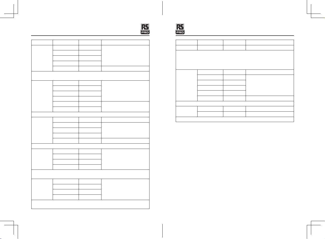
5.10 AC/DC Current Measurements
5.11 Resistance Measurements
• Insert the black test lead into the COM input jack and the red test lead into the V input
jack. If measuring DC voltage, touch the red test lead to the positive side of the circuit
and the black test lead to the negative side of the ncircuit.
• Touch the test leads to the circuit under test.
• Read the voltage on the LCD display.
WARNINGS: Observe all safety precautions when working on live circuits. Do not
measure current on circuits that exceed 1000V. Measurements in the 10A range
should be limited to 30 seconds maximum every 15 minutes.
• Insert the black test lead into the negative COM input jack.
• For current measurements up to 10A, set the rotary function switch to the 10A position
and insert the red test lead into the 10A input jack.
• For current measurements up to 600mA, set the rotary function switch to the mA
position and insert the red test lead into the μA mA input jack.
• For current measurements up to 6000μA, set the rotary function switch to the μA
position and insert the red test lead into the μA mA input jack.
• Momentarily press the MODE button to select AC or DC current. The AC “~” or DC
" ~"symbol will appear on the LCD display.
• Remove power from the circuit under test, then open up the circuit at the point where
you wish to measure current.
• Touch the test lead probes in series with the circuit being measured. For DC current,
touch the red probe to the positive side of the circuit and touch the black probe to the
negative side of the circuit.
• Apply power to the circuit.
• Read the current on the LCD display.
WARNING: Never test resistance on a live circuit.
• Set the rotary function switch to the Ω position.
• Press the MODE button until the “ Ω ” symbol appears on the LCD display.
• Insert the black test lead into the COM input jack and the red test lead into the input jack.
True RMS Digital Multimeter/ English
13/12/2017 Version No. 001
• Momentarily press the MODE button to select AC or DC voltage. The AC “~” or DC
" ~" symbol will appear on the LCD display.
• Insert the black test lead into the COM input jack and the red test lead into the V input jack.
• Touch the test lead probes to the circuit under test. If measuring DC voltage, touch the
red test lead to the positive side of the circuit and the black test lead to the negative
side of the circuit.
• Read the voltage on the LCD display.
5.8 Frequency and % Duty Cycle Measurements
5.9 Low Z Voltage
WARNING: Observe all safety precautions when working on live voltages.
• Set the rotary function switch to the V ~HZ % position.
• To select Frequency, press and hold the MODE button until the “Hz” symbol appears on
the LCD display. To select % Duty Cycle, press and hold the MODE a second time until
the “%” appears on the LCD display.
• Insert the black test lead into the COM input jack and the red test lead into the V input jack.
• Touch the test lead probes to the circuit under test.
• Read the frequency or % duty cycle on the LCD display.
• To return to AC voltage, press and hold the MODE button a third time until the “~ ”
symbol appears on the LCD display.
NOTE: The Frequency function can only be accessed when the meter is set to AC
voltage.
WARNING: Observe all safety precautions when working on live voltages.
Do not connect to circuits that exceed 600V AC/DC when the meter is set to Low Z.
Low Z is used when there is a suspicion of a “ghost” voltage. Ghost voltages are
present when non-powered wires are in close proximity to wires powered by AC voltage.
Capacitive coupling between wires make it appear that nonpowered wires are connected
to a real source of voltage. The Low Z setting places a load on the circuit, which
dissipates and greatly reduces ghost voltage.
• Set the rotary function switch to the Low Z position.
• Momentarily press the MODE button to select AC or DC voltage. The AC “~” or DC
" ~"symbol will appear on the LCD display.
True RMS Digital Multimeter/ English
13/12/2017 Version No. 001

10 11
• Touch the test lead probes to the component under test. If the component is installed
in a circuit, it is best to disconnect one side before testing to eliminate interference with
other devices.
• Read the resistance in on the LCD display.
5.12 Continuity Test
5.13 Diode Test
5.14 Capacitance Measurements
WARNING: Never test continuity on a live circuit.
WARNING: Never test diodes in a live circuit.
WARNING: Safely discharge capacitors before taking capacitance measurements.
• Set the rotary function switch to the Ω position.
• Press the MODE button until the " ” symbol appears on the LCD display.
• Insert the black test lead into the COM input jack and the red test lead into the Ω input jack.
• Touch the test lead probes to the device or wire under test.
• A beeper will sound if the resistance is approximately 50 ±5 or less and the resistance
value will be shown on the LCD display.
• Set the rotary function switch to the Ω position.
• Press the MODE button until the " ” symbol appears on the LCD display.
• Insert the black test lead into the COM input jack and the red test lead into the Ω input jack.
• Touch the test lead probes to the diode under test.
• Forward voltage will indicate 0.4 to 0.7 on the display. Reverse voltage will indicate
“OL”. Shorted devices will indicate near 0 and an open device will indicate “OL” in both
polarities.
Red
Probe
Red
Probe
Black
Probe
Black
Probe
Forward test Reverse test
• Set the rotary function switch to the CAP position.
True RMS Digital Multimeter/ English
13/12/2017 Version No. 001
5.15 Temperature Measurements
5.16 Battery Replacement
5.17 Fuse Replacement
• Insert the black test lead into the COM input jack and the red test lead into the CAP
input jack.
• Touch the test lead probes to the capacitor under test.
• Read the capacitance value on the LCD display. It may take up to a minute to get a
stable reading on large capacitors.
• Set the rotary function switch to the °F °C position.
• Press the MODE button to select readings in °F or °C.
• Connect the Temperature Probe to the Banana Plug Adapter. Note the – and + markings
on the adapter. Connect the adapter to the meter, making sure the – side goes into the
COM input jack and the + side goes into the °C °F input jack.
• Touch the tip of the Temperature Probe to the object being measured. Keeps the probe
touching the object until the reading stabilizes(about 30 sec).
• Read the temperature on the LCD display.
WARNING: To avoid electric shock, remove the test leads from the meter before
removing the battery/fuse cover.
WARNING: To avoid electric shock, do not operate meter until the battery/fuse
cover is securely fastened to the meter.
WATRNING: To avoid electric shock, remove the test leads from the meter before
removing the battery/fuse cover.
• Lift up the tilt stand.
• Loosen the one Phillips screw on the battery/fuse cover.
• Remove the battery/fuse cover.
• Replace the batteries with four AAA batteries.
• Observe polarity as shown inside battery compartment.
• Install the battery/fuse cover and tighten the screw.
• Loosen the one Phillips screw on the batter/fuse cover.
• Remove the battery/fuse cover.
True RMS Digital Multimeter/ English
13/12/2017 Version No. 001

12 13
True RMS Digital Multimeter/ English
Function Range Resolution Accuracy ±(% of reading + digits)
Low Z
DC Voltage
600mV 0.1mV
±(3.0% + 40)
6V 1mV
60V 10mV
600V 0.1V
Input Protection: 600V AC RMS or 600V DC
Input Impedance: Approx. 3kΩ
Frequency
(electrical)
9.999Hz 0.001Hz
±(1.0% + 5)
99.99Hz 0.01Hz
999.9Hz 0.1Hz
9.999kHz 1Hz
Input Protection: 600V AC RMS or 600V DC
Sensitivity: <8V RMS
Duty Cycle 20.0% to 80.0% 0 .1% ±(1.2% + 2)
Input Protection: 600V AC RMS or 600V DC
Pulse Width: 0.1 to 100mS
Frequency Range: 5Hz to 10kHz
Sensitivity: >8V RMS
AC Current
600μA 0.1μA
±(1.5% + 3)
6000μA 1μA
60mA 10μA
600mA 0.1mA
10A 10mA ±(2.0% + 5)
Overload Protection: μA, mA ranges: 800mA/1000V Fuse
10A range: 10A/1000V Fuse
Accurary specified from 5% to 100% of the measuring rang.
AC current bandwidth: 45 to 500Hz
Distorted, pulsed, triangle or trapezia waveform.
Accuracy: ±(10%rdg + 10dgt)
13/12/2017 Version No. 001
• Gently remove fuse and install new fuse into the holder.
• Always use a UL recognized fuse of the proper size and value: 800mA/1000V (6.3 x
32mm) fast blow for the μA/mA ranges and 10A/1000V(10 x 38mm) fast blow for the
10A range.
• Install the back cover and tighten the screw.
WARNING: To avoid electric shock, do not operate meter until the battery/fuse cover
is securely fastened to the meter.
6. Specications
Accuracy is stated at 65°F to 83°F(18°C to 28°C), less than 70% 1- relative humidity
Function Range Resolution Accuracy ±(% of reading + digits)
AC Voltage
6V 1mV
±(0.8% + 8)60V 10mV
600V 0.1V
1000V 1V ±(1.0% + 3)
Input Protection: 1000V AC RMS or 1000V DC
Accurary specified from 5% to 100% of the measuring rang.
AC voltage accuracy bandwidth: 45Hz to 1000Hz
Distorted, pulsed, triangle or trapezia waveform.
Accuracy: ±(10%rdg + 10dgt)
Low Z
AC Voltage
6V 1mV
±(3.0% + 40)60V 10mV
600V 0.1V
Input Protection: 600V AC RMS or 600V DC
Accurary specified from 5% to 100% of the measuring rang.
Input Impedance: Approx. 3kΩ
DC Voltage
600mV 0.1mV ±(0.5% + 8)
6V 1mV
±(0.5% + 5)60V 10mV
600V 0.1V
1000V 1V ±(0.8% + 3)
Input Protection: 1000V AC RMS or 1000V DC
13/12/2017 Version No. 001
True RMS Digital Multimeter/ English

14 15
Function Range Resolution Accuracy ±(% of reading + digits)
Duty Cycle 20.0% to 80.0% 0 .1% ±(1.2% + 2)
Input Protection: 600V AC RMS or 600V DC
Pulse Width: 0.1 to 100mS
Frequency Range: 5Hz to 10kHz
Sensitivity: >8V RMS
Capacitance
60nF 10pF ±(5.0% + 35)
600nF 100pF
±(3.0% + 5)
6μF 0.001μF
60μF 0.01μF
600μF 0.1μF
6000μF 1μF ±(5.0% + 5)
Input Protection: 600V AC RMS or 600V DC
Temperature -4 F to 1400°F 0.1°F ±(2.0% + 9°F)
-20°C to 760°C 0.1°C ±(2.0% + 5°C)
Input Protection: 600V AC RMS or 600V DC
True RMS Digital Multimeter/ English
13/12/2017 Version No. 001
Function Range Resolution Accuracy ±(% of reading + digits)
DC Current
600μA 0.1μA
±(3.0% + 40)
6000μA 1μA
60mA 10μA
600mA 0.1mA
10A 10mA 10A ±(1.5% + 5)
Overload Protection: μA, mA ranges: 800mA/1000V Fuse
10A range: 10A/1000V Fuse
Resistance
600Ω 0.1Ω
±(1.0% + 5)
6kΩ 1Ω
60kΩ 10Ω
600kΩ 100Ω
6MΩ 1kΩ ±(2.0% + 10)
60MΩ 10kΩ
Input Protection: 600V AC RMS or 600V DC
DC Voltage
600mV 0.1mV ±(0.5% + 8)
6V 1mV
±(0.5% + 5)60V 10mV
600V 0.1V
1000V 1V ±(0.8% + 3)
Input Protection: 1000V AC RMS or 1000V DC
Low Z
DC Voltage
600mV 0.1mV
±(3.0% + 40)
6V 1mV
60V 10mV
600V 0.1V
Input Protection: 600V AC RMS or 600V DC
Input Impedance: Approx. 3kΩ
Frequency
(electrical)
9.999Hz 0.001Hz
±(1.0% + 5)
99.99Hz 0.01Hz
999.9Hz 0.1Hz
9.999kHz 1Hz
Input Protection: 600V AC RMS or 600V DC
Sensitivity: <8V RMS
True RMS Digital Multimeter/ English
13/12/2017 Version No. 001

1
Manuel d'instructions
RS-965T
No d'inventaire: 146-9098
Multimètre numérique TRUE RMS
FR
Multimètre numériqueTRUE RMS / Francais
13/12/2017 Version No. 001
1. Introduction
Le multimètre True RMS de Southwire offre des mesures pour des lectures du courant
alternatif plus précises et un réglage Low Z pour éliminer les erreurs causées par les
tensions «fantômes». Les fonctions comprennent la tension et le courant alternatif /
courant continu , la résistance, la continuité, la capacité, la fréquence, le rapport cyclique,
la température et le test de diode. Le True RMS Multimeter offre également la commodité
d'une lampe LED intégrée. Ce compteur est entièrement testé et calibré et, avec une
utilisation appropriée, fournira de nombreuses années de service fiable.
2. AVERTISSEMENTS
• Lisez, comprenez et respectez les règles de sécurité et les instructions de ce manuel
avant d'utiliser ce lecteur.
• Les caractéristiques de sécurité du compteur peuvent ne pas protéger l'utilisateur si
elles ne sont pas utilisées conformément aux instructions du fabricant.
• Assurez-vous que les cordons sont bien insérés dans les prises d'entrée et maintenez les
doigts éloignés des pointes de la sonde métallique lors de la prise de mesures.
• Avant de changer de fonction à l'aide du sélecteur, déconnectez toujours les cordons du
circuit testé.
• N'utilisez que des cordons homologués UL avec la classification de sécurité appropriée.
• Se conformer à tous les codes de sécurité applicables. Utiliser un équipement de
protection individuelle approuvé lorsque l'on travaille à proximité de circuits électriques
sous tension, en particulier en ce qui concerne le potentiel d'arc électrique.
• Soyez prudent sur les circuits sous tension. Des tensions supérieures à 30 V CA
efficaces, 42 V CA crête ou 60 V CC présentent un risque d'électrocution.
• Ne pas utiliser si le multimètre ou les cordons semblent endommagés.
• Vérifiez le fonctionnement avant d'utiliser le compteur en mesurant une tension réelle connue.
• N'utilisez pas le lecteur dans des environnements humides ou pendant des orages électriques.
• N'utilisez pas le lecteur de glycémie ou des vapeurs, de la poussière ou des gaz explosifs.
• N'utilisez pas le lecteur s'il ne fonctionne pas correctement. La protection peut être
compromise.
• Ne faites pas fonctionner le compteur lorsque l'avertissement de batterie faible est
activé. Remplacez les piles immédiatement.
• N'appliquez pas de tension ou de courant dépassant les limites d'entrée maximales du
compteur.

2 3
Fonction Maximum d'entrée
Tension alternative ou continue 1000V de courant alternatif RMS/1000V du
courant continu
Low Z 600V du courant alternatif RMS/600V du
courant continu
μA, mA Courant alternatif/ continu 800mA 1000V fusible à action rapide
Courant alternatif ou continu de
10A
Fusible à l’action rapide 10A 1000V
(10A pour 30 secondes maximum toutes les 15
minutes)
Résistance, Continuité, Test de diode,
Capacité, Fréquence, Cycle de service
600V du courant alternatif RMS/600V du
courant continu
Température 600V du courant alternatif RMS/600V du
courant continu
Isolation Classe 2, double isolation
Enveloppe Double moulée de IP67 imperméable à l'eau et à la poussière
Test de Diode Courant à 1,5mA typique, tension de circuit ouvert 3V
Test de continuité Signal sonore si la résistance est d'environ 50 ± 5Q ou moins
Indication de la batterie faible
" " estaffiché
Vie de la batterie 150 heures (Pour s’éteindre)
L’écran L’affichage avec un compte de 6000 LCD
Indication de dépassement “OL” estaffiché
Polarité Le symbole moins "-" est affiché pour la polarité négative
Taux de mesure 3 lectures par seconde, nominal
Arrêtautomatique Après environ 15 minutes d'inactivité
Impédanced'entrée Tension du courant alternative / du courant continu de 10MQ
Low Z (faible Z) Environ d’une Impédance d'entrée de 3kΩ
Réponse du courant
alternative True RMS
Bande passante du
courant alternatif 2kHz
Limites d'entrée
3. General Specications
Bande passante du
courant alternatif
Quatre piles alcalines "AAA" de 1.5V 800mA 1000V (6.3 x
32mm) souffle rapide
Fusible 10A 1000V(10 x 38mm) soufflé rapide
Environnementexploité De 0oC à 40 oC (32 oF à 104 oF) à <70% d'humidité relative
Environnement de
stockage
De -10 oC à 60 oC (14 oF à 140 oF) à <80% d'humidité
relative à 2000
Altitude mètres maximum
Dimensions / Poids 170 x75x 48mm/386g
Sécurité Conforme à UL 61010-1 v.3 pour la mesure
Catégorie IV 600V et Catégorie III 1000V, Degré de pollution 2
3-1.Signes de sécurité internationaux
PDanger potentiel. Indique que l'utilisateur doit se reporter au manuel pour des
informations de sécurité importantes.
Indique que des tensions dangereuses peuvent être présentes.
L'équipement est protégé par une double isolation ou renforcée.
Indique que la ou les bornes marquées ne doivent pas être connectées à un circuit où
la tension par rapport à la terre dépasse la cote de sécurité maximale du compteur.
Catégorie Brief Description Applications
CAT II Récipients monophasés
et charges connectées
- Appareils ménagers, outils électriques
- Sorties à plus de 30 pieds (10 m) d'une
source catégorie III - Pointes à plus de
60 pi (20 m) d'une source CAT IV
3-2. Nombre de catégories de sécurité
Multimètre numériqueTRUE RMS / FrancaisMultimètre numériqueTRUE RMS / Francais
13/12/2017 Version No. 00113/12/2017 Version No. 001

4 5
Catégorie Brief Description Applications
CAT III
Circuits triphasés et
circuits d'éclairage
monophasés dans les
bâtiments commerciaux
- Équipements dans des installations
fixes telles que des moteurs triphasés,
des appareillages de commutation et des
panneaux de distribution
- Circuits d'éclairage dans les bâtiments
commerciaux
- Lignes d'alimentation dans les
installations industrielles
-Tout appareil ou circuit de dérivation
proche d'une source catégorie III
CAT IV
Point de connexion
à l'alimentation
du secteur et aux
conducteurs extérieurs
- Panneaux de distribution primaires
- Lignes aériennes ou souterraines à des
bâtiments détachés.
- Pompes extérieures
La classification de la catégorie (CAT) et la tension nominale sont déterminées par une
combinaison du compteur, des sondes et de tous les accessoires connectés au compteur
et aux sondes. La note de combinaison est la plus faible de chaque composant individuel.
AVERTISSEMENT: Le fonctionnement est limité aux applications catégorie II lorsque
les pointes isolées sont retirées d'une ou des deux sondes. Reportez-vous à la section
Limites d'entrée dans ce manuel pour les tensions maximales.
3-3. Maintenance
Ce multimètre est conçu pour fournir des années de service fiable, si les instructions
d'entretien suivantes sont effectuées:
• GARDEZ LE COMPTEUR SEC. S'il est mouillé, essuyez-le.
• UTILISER ET STOCKER LE COMPTEUR DANS DES TEMPÉRATURES NORMALES. Les
températures extrêmes peuvent raccourcir la durée de vie des pièces électroniques et
fausser ou faire fondre les pièces en plastique.
• MANIPULER DOUCEMENT ET ATTENTIVEMENT le compteur . Eviter la chute du compteur
qui peut endommager l’appareil.
les parties électroniques ou le boîtier.
• GARDEZ LE COMPTEUR PROPRE. Essuyez le boîtier de temps en temps avec un chiffon
humide. N'utilisez PAS de produits chimiques, de solvants de nettoyage ou de détergents.
• UTILISEZ UNIQUEMENT DES PILES FRAÎCHES DE LA TAILLE ET DU TYPE RECOMMANDÉS.
Retirez les piles usagées ou faibles afin qu'elles ne fuient pas et n'endommagent pas l'appareil.
• SI LE COMPTEUR DOIT ÊTRE STOCKÉ PENDANT UNE LONGUE PÉRIODE, les piles
doivent être retirées pour éviter d'endommager l'appareil.
4. Description
1. Ecran LCD
2. Le bouton REL
3. Le bouton Gamme
4. Le bouton MODE
5. Commutateur rotatif
6. Prise d'entrée 10A
7. μA, prise d'entrée mA
8. Prise d'entrée COM
9. Prise d'entrée V/ Ω/ / / CAP/ Hz%/ oC oF
10. Touche rétro-éclairage / HOLD
11. Bouton PEAK / lampe d’éclairage
12. Bouton MAX / MIN / AVG
13. Rétroéclairage automatique
14. Lampe de poche
Multimètre numériqueTRUE RMS / FrancaisMultimètre numériqueTRUE RMS / Francais
13/12/2017 Version No. 00113/12/2017 Version No. 001

6 7
4-1.Symboles utilisés sur l'écran LCD
VVolts
AAmpères
~Courant alternatif
Courant continu
Signe moins
ΩOhms
Continuité
Test de Diode
FFarads(capacité)
Hz Hertz(frequence)
%Pourcentage (taux de service)
oFDegrés Fahrenheit
oCDegrés Celsius
nnano(10 )
μ-6 micro(10 )
m-3 millidO )
k3 kilo(10)
M6 mega(10 )
OL Surcharge
Arrêt automatique
Batterie faible
AUTO Auto variant
HOLD Afficher l'attente
MAX/MIN/AVG Maximum/ Minimum/ Moyenne
Peak Pointe d’attente
REL Relatif
5-Opération
5-1. Bouton Gamme
Le mode Autorange sélectionne automatiquement la gamme appropriée pour la mesure
effectuée et est généralement le meilleur mode pour la plupart des applications. Pour les
situations nécessitant la sélection manuelle d'une gamme, procédez comme suit:
• Appuyez momentanément sur le bouton RANGE. L'indicateur "AUTO" ne s'affichera plus
sur l'écran LCD.
• Appuyez momentanément sur le bouton RANGE pour parcourir les gammes disponibles
jusqu'à ce que la gamme désirée soit sélectionnée.
• Pour quitter le mode de télémétrie manuelle, maintenez enfoncé le bouton gamme jusqu'à
ce que l'indicateur "AUTO" réapparaisse.
5-2. Bouton du MODE
Utilisé pour sélectionner le courant alternatif ou Courant continu , Fréquence ou cycle de
fonctionnement, Résistance, Continuité ou Test de diode, et °C ou °F.
5-3. REL Button
La fonction relative met à zéro la lecture sur l'écran et la mémorise comme référence. Les
lectures subséquentes seront affichées en tant que différence entre la mesure réelle et
la valeur de référence enregistrée. Pour l'activer, appuyez sur le bouton REL. L'indicateur
"REL" apparaîtra sur l'écran LCD avec la lecture. Appuyez à nouveau sur le bouton REL
pour revenir au fonctionnement normal.
REMARQUE: Le bouton de gamme ne fonctionne pas sur la fréquence, le rapport
cyclique, la capacité ou la température.
REMARQUE: Le compteur ne fonctionne pas automatiquement lorsque le mode relatif
est actif. L'affichage indiquera OL si la différence dépasse la gamme. Lorsque cela se
produit, quittez REL et utilisez le bouton gamme pour sélectionner une gamme plus
élevée. REL ne fonctionne pas sur la fréquence, le cycle de service, la capacité ou
low Z.
5-4. Bouton MAX / MIN / AVG
• Appuyez momentanément sur le bouton MAX / MIN / AVG pour activer le mode MAX /
MIN. L'indicateur "MAX" apparaît sur l'écran LCD. Le compteur affichera et maintiendra
la lecture maximale et se mettra à jour lorsqu'un «MAX» plus élevé se produira.
• Appuyez momentanément sur le bouton MAX / MIN / AVG pour afficher la lecture la plus
basse. L'indicateur "MIN" apparaîtra sur l'écran LCD. Le compteur affichera et
maintiendra la lecture minimale et se mettra à jour quand un «MIN» plus bas se produira.
• Appuyez à nouveau brièvement sur le bouton MAX / MIN / AVG pour afficher la lecture
moyenne. Le symbole "AVG" apparaît sur l'écran LCD. Le compteur affichera la moyenne
courante et se mettra à jour lorsque la valeur moyenne changera.
• Appuyez sur le bouton MAX / MIN / AVG et maintenez-le enfoncé pour terminer MAX /
MIN et retourner au fonctionnement normal.
Multimètre numériqueTRUE RMS / FrancaisMultimètre numériqueTRUE RMS / Francais
13/12/2017 Version No. 00113/12/2017 Version No. 001

8 9
REMARQUE: MAX / MIN ne fonctionne pas sur la fréquence, le cycle de service, la
capacité ou la température.
5-5. Rétro-éclairage/ Bouton HOLD
Pour geler la lecture sur l'écran LCD, appuyez momentanément sur le bouton HOLD.
L'indicateur "HOLD" sera affiché pendant la lecture. Appuyez de nouveau brièvement sur
le bouton HOLD pour quitter HOLD et revenir au fonctionnement normal.
Pour allumer le rétroéclairage, maintenez le bouton HOLD enfoncé jusqu'à ce que le
rétroéclairage s'allume. Pour éteindre le rétroéclairage, maintenez le bouton HOLD enfoncé
jusqu'à ce que le rétroéclairage s'éteigne.
Rétroéclairage automatique
Lorsque le compteur est dans l'obscurité, le rétroéclairage peut être automatiquement
ouvert, sans être contrôlé par le bouton.
5-6.Rétro-éclairage / Bouton PEAK
Appuyez momentanément sur et le bouton PEAK pour allumer et éteindre la lampe. La
fonction PEAK est accessible lors de la mesure de la tension ou du courant alternatif. Il
capture et affiche le pic positif le plus élevé et le pic négatif le plus élevé de la forme d'onde
du courant alternatif.
• Appuyez sur le bouton PEAK et maintenez-le enfoncé jusqu'à ce que «Peak MAX»
apparaisse sur l'écran LCD. Le lecteur affichera la lecture la plus élevée et mettra à jour
la lecture lorsqu'un pic positif plus élevé se produit.
• Pour voir le pic négatif le plus élevé, appuyez sur le bouton PEAK pendant environ une
seconde. "Peak MIN" apparaîtra sur l'écran LCD et le lecteur affichera et maintiendra la
lecture la plus élevée. Le lecteur mettra à jour la lecture lorsqu'un pic négatif plus élevé
se produit.
• Appuyez sur le bouton PEAK pendant environ une seconde pour basculer entre les
valeurs Peak MAX et Peak MIN.
• Appuyez sur le bouton PEAK et maintenez-le enfoncé pour quitter PEAK et revenir au
fonctionnement normal.
REMARQUE: Le compteur ne fonctionne pas automatiquement lorsque le mode Peak
est actif. L'affichage lira OL si la gamme est dépassée. Lorsque cela se produit, quittez
Peak et utilisez le bouton gamme pour sélectionner une gamme plus élevée. Le pic ne
fonctionne pas sur DCV, DCA, Fréquence, Cycle de service, Capacité ou Low Z.
5-7.Tension du courant alternatif/ du courant continu
AVERTISSEMENT: Observez toutes les précautions de sécurité lorsque vous travaillez
sur des tensions réelles.
AVERTISSEMENT: Observez toutes les précautions de sécurité lorsque vous travaillez
sur des tensions réelles.
• Réglez le sélecteur de fonction rotative en position V ~ HZ%.
• Appuyez momentanément sur le bouton MODE pour sélectionner la tension du courant
alternatif ou du courant continu . Le symbole AC "~" ou DC "~" apparaît sur l'écran
LCD.
• Insérez le cordon noir dans la prise d'entrée COM et le fil rouge dans la prise d'entrée V.
• Touchez les sondes du fil sur le circuit testé. Si vous mesurez la tension du courant
continu , touchez le fil rouge sur le côté positif du circuit et le fil noir sur le côté négatif
du circuit.
• Lisez la tension sur l'écran LCD.
5-8.Frequence et le pourcentage % du Cycle
• Réglez le commutateur rotatif en position V ~ HZ%.
• Pour sélectionner la fréquence, appuyez sur le bouton MODE et maintenez-le enfoncé
jusqu'à ce que le symbole "Hz" apparaisse sur l'écran LCD. Pour sélectionner le % Duty
Cycle, appuyez et maintenez le MODE une seconde fois jusqu'à ce que "%" apparaisse
sur l'écran LCD.
• Insérez le cordon noir dans la prise d'entrée COM et le fil rouge dans la prise d'entrée V.
• Touchez les sondes du fil sur le circuit testé.
• Lisez la fréquence ou le rapport cyclique en % sur l'écran LCD.
• Pour revenir à la tension du courant alternaif, appuyez et maintenez le bouton MODE
une troisième fois jusqu'à ce que le symbole "~" apparaisse sur l'écran LCD.
REMARQUE: La fonction Fréquence n'est accessible que lorsque le multimètre est
réglé sur la tension alternative.
Multimètre numériqueTRUE RMS / FrancaisMultimètre numériqueTRUE RMS / Francais
13/12/2017 Version No. 00113/12/2017 Version No. 001

10 11
5-9.Faible tension
AVERTISSEMENT: Observez toutes les précautions de sécurité lorsque vous travaillez
sur des tensions réelles. Ne pas connecter à des circuits qui dépassent 600V AC / DC
lorsque le compteur est réglé sur Low Z.
Low Z est utilisé en cas de suspicion de tension "fantôme". Des tensions fantômes sont
présentes lorsque des fils non alimentés sont à proximité de fils alimentés par une tension
alternative. Le couplage capacitif entre les fils donne l'impression que les fils non alimentés
sont connectés à une source de tension réelle. Le réglage Low Z place une charge sur le
circuit, qui se dissipe et réduit considérablement la tension fantôme.
• Réglez le commutateur rotatif sur la position Low Z.
• Appuyez momentanément sur le bouton MODE pour sélectionner la tension CA ou CC. Le
symbole AC "~" ou DC " ~" apparaît sur l'écran LCD.
• Insérez le cordon noir dans la prise d'entrée COM et le fil rouge dans la prise d'entrée
V. Si vous mesurez la tension CC, touchez le fil rouge sur le côté positif du circuit et le
fil noir sur le côté négatif du circuit.
• Touchez les cordons au circuit testé.
• Lisez la tension sur l'écran LCD.
5-10. les mesures du courant alternatif / du courant continu
AVERTISSEMENTS: Respectez toutes les précautions de sécurité lorsque vous
travaillez sur des circuits sous tension. Ne mesurez pas le courant sur les circuits
dépassant 1000V. Les mesures dans la gamme de 10A doivent être limitées à 30
secondes maximum dans toutes les 15 minutes.
• Insérez le cordon noir dans la prise COM négative.
• Pour les mesures de courant jusqu'à 10A, réglez le commutateur rotatif sur la position
de 10A et insérez le cordon rouge dans la prise d'entrée 10A.
• Pour les mesures de courant jusqu'à 600 mA, réglez le commutateur de fonction rotatif
sur la position mA et insérez le cordon de test rouge dans la prise d'entrée mA μA.
• Pour des mesures de courant jusqu'à 6000 μA, réglez le commutateur rotatif sur la
position μA et insérez le cordon rouge dans la prise d'entrée μA MA.
• Appuyez momentanément sur le bouton MODE pour sélectionner le courant alternatif ou
continu. Le symbole AC "~" ou DC " ~" apparaît sur l'écran LCD.
• Coupez l'alimentation du circuit testé, puis ouvrez le circuit à l'endroit où vous souhaitez
mesurer le courant.
• Touchez les sondes en série avec le circuit à mesurer. Pour le courant continu, touchez
la sonde rouge sur le côté positif du circuit et touchez la sonde noire sur le côté négatif
du circuit.
• Appliquer l'alimentation au circuit.
• Lisez le courant sur l'écran LCD.
5-11. Mesures de résistance
AVERTISSEMENT: Ne jamais tester la résistance sur un circuit sous tension.
• Réglez le commutateur rotatif en position Ω
• Appuyez sur le bouton MODE jusqu'à ce que le symbole "Ω" apparaisse sur l'écran LCD.
• Insérez le cordon noir dans la prise d'entrée COM et le fil rouge dans la prise .
• Touchez les sondes du fil sur le composant testé. Si le composant est installé dans un
circuit, il est préférable de le déconnecter d'un côté avant de le tester pour éliminer les
interférences avec d'autres appareils.
• Lisez la résistance sur l'écran LCD.
5-12. Test de continuité
5-13.Teste de Diode
AVERTISSEMENT: Ne jamais tester la continuité sur un circuit sous tension.
• Réglez le commutateur de fonction rotative en position Ω.
• Appuyez sur le bouton MODE jusqu'à ce que le symbole "" apparaisse sur l'écran LCD.
• Insérez le fil noir dans la prise COM et le fil rouge dans la prise fi.
• Touchez les sondes du cordon de l'appareil ou au fil sous test.
• Un bip retentira si la résistance est d'environ 50 ±50 ou moins et la valeur de
résistance sera affichée sur l'écran LCD.
AVERTISSEMENT: Ne jamais tester les diodes dans un circuit sous tension.
• Réglez le commutateur de fonction rotative en position Ω.
• Appuyez sur le bouton MODE jusqu'à ce que le symbole "" apparaisse sur l'écran LCD.
• Insérez le cordon noir dans la prise COM et le fil rouge dans la prise Ω.
• Touchez les sondes du fil à la diode testée.
Multimètre numériqueTRUE RMS / FrancaisMultimètre numériqueTRUE RMS / Francais
13/12/2017 Version No. 00113/12/2017 Version No. 001

12 13
• La tension directe indique 0,4 à 0,7 sur l'affichage. La tension inverse indiquera "OL".
Les dispositifs en court-circuit indiqueront près de 0 et un dispositif ouvert indiquera
"OL" dans les deux polarités.
Red
Probe
Red
Probe
Black
Probe
Black
Probe
Forward test Reverse test
5-14.Capacités
AVERTISSEMENT: déchargez les condensateurs en toute sécurité avant de prendre
des mesures de capacité.
Réglez le commutateur de fonction rotative en position CAP.
Insérez le cordon noir dans la prise COM et le fil rouge dans la Prise d'entrée CAP.
• Touchez les sondes du cordon sur le condensateur testé.
• Lisez la valeur de capacité sur l'écran LCD. Cela peut prendre jusqu'à une minute pour
obtenir une lecture stable sur les grands condensateurs.
5-15.Température
• Réglez le commutateur de fonction rotative en position °F °C.
• Appuyez sur le bouton MODE pour sélectionner les lectures en °F ou °C.
• Connectez la sonde à l'adaptateur de fiche banane. Notez les marques -et +sur
l'adaptateur. Connectez l'adaptateur à l'appareil, en vous assurant que le côté - va dans
la prise COM et le côté + dans la prise ° C ° F.
• Touchez l'extrémité de la sonde sur l'objet à mesurer. Maintient la sonde en contact
avec l'objet jusqu'à ce que la lecture se stabilise (environ 30 secondes).
• Lisez la température sur l'écran LCD.
5-16 Remplacement de la batterie
AVERTISSEMENT: Pour éviter les chocs électriques, retirez les cordons du
multimètre avant de retirer le couvercle de batterie / fusible.
• Soulevez le support d'inclinaison.
• Desserrez la vis cruciforme du couvercle de la batterie / du fusible.
• Enlever le couvercle de batterie / fusible.
• Remplacez par quatre piles AAA.
• Respectez la polarité indiquée dans le compartiment des piles.
• Installez le couvercle de batterie / fusible et serrez la vis.
AVERTISSEMENT: Pour éviter les chocs électriques, ne pas utiliser l'appareil tant
que le couvercle de la batterie / du fusible n'est pas solidement fixé au compteur.
5-17.Remplacement de fusible
AVERTISSEMENT: Pour éviter les chocs électriques, retirez les cordons du multimètre
avant de retirer le couvercle de batterie / fusible.
• Desserrez la vis Phillips sur le couvercle de la batterie / du fusible.
• Enlever le couvercle de batterie / fusible.
• Retirez délicatement le fusible et installez un nouveau dans le support.
• Toujours utiliser un fusible homologué d’une taille UL et de la valeur appropriées:
soufflage rapide de 800mA / 1000V (6.3 x 32mm) pour les gammes μA/ mA et 10A/
1000VCI0 x 38mm) pour la gamme 10A.
• Installez le couvercle arrière et serrez la vis.
AVERTISSEMENT: Pour éviter les chocs électriques, n'utilisez pas l'appareil tant
que le couvercle de la batterie / du fusible n'est pas solidement fixé au compteur.
6-Spécications
La précision est indiquée entre 18 °C et 28 °C (65 °F et 83 °F), moins de 70% d'humidité
relative 1-
Fonction Gamme Résolution Précision ± (% de la lecture + chiffres)
Tension
alternative
6V 1mV
±(0.8% + 8)60V 10mV
600V 0.1V
1000V 1V ±(1.0% + 3)
Protection d'entrée: 1000V du courant alternatif RMS ou 1000V du courant continu
Précis spécifié de 5 à 100% de la mesure a sonné.
Bande passante avec précision de tension alternative: 45Hz à 1000Hz
Forme d'onde déformée, pulsée, triangulaire ou trapézienne.
Précision: ± (10% rdg + 10dgt)
Multimètre numériqueTRUE RMS / FrancaisMultimètre numériqueTRUE RMS / Francais
13/12/2017 Version No. 00113/12/2017 Version No. 001

14 15
Fonction Gamme Résolution Précision ± (% de la lecture + chiffres)
Low Z
Tension
alternative
6V 1mV
±(3.0% + 40)60V 10mV
600V 0.1V
Protection d'entrée: 600V Ru courant alternatif MS ou 600V du courant continu
Précision spécifiée de 5 à 100% de gamme
Impédance d'entrée: à peu près à 3 kΩ
Courant
continu
600mV 0.1mV ±(0.5% + 8)
6V 1mV
±(0.5% + 5)60V 10mV
600V 0.1V
1000V 1V ±(0.8% + 3)
Protection d'entrée: 1000V courant alternative RMS ou 1000V courant continu
Low Z Tension
continu
600mV 0.1mV
±(3.0% + 40)
6V 1mV
60V 10mV
600V 0.1V
Protection d’entrée : 600V AC RMS or 600V DC
Impédance d’entrée : Approx. 3kΩ
Fréquence
(électrique)
9.999Hz 0.001Hz
±(1.0% + 5)
99.99Hz 0.01Hz
999.9Hz 0.1Hz
9.999kHz 1Hz
Protection d’entrée : 600V courant alternative RMS ou 600V courant continu
Sensibilité: <8V RMS
Cycle de service 20.0% à 80.0% 0.1% ±(1.2%+ 2)
Protection d'entrée: 600V courant alternatif RMS ou 600V courant continu
Largeur d'impulsion: 0,1 à 100 mS
Gamme de fréquence: 5hz à 10 kHz
Sensibilité:> 8V RMS
Fonction Gamme Résolution Précision ± (% de la lecture + chiffres)
Courant
alternatif
600μA 0.1μA
±(1.5% + 3)
6000μA 1μA
60mA 10μA
600mA 0.1mA
10A 10mA ±(2.0% + 5)
Protection contre les surcharges: μA, gamme mA: fusible 800mA / 1000V
Gamme 10A: Fusible 10A / 1000V
Précision spécifié de 5% à 100% de la mesure a sonné.
Bande passante de courant alternatif: 45 à 500Hz
Forme d'onde déformée, pulsée, triangulaire ou trapézienne.
Précision: ± (10% rdg + 10dgt)
Courant
continu
600μA 0.1μA
±(3.0% + 40)
6000μA 1μA
60mA 10μA
600mA 0.1mA
10A 10mA 10A ±(1.5% + 5)
Protection contre les surcharges: μA, gamme mA: fusible 800mA / 1000V
Gamme 10A: Fusible 10A / 1000V
Résistance
600Ω 0.1Ω
±(1.0% + 5)
6kΩ 1Ω
60kΩ 10Ω
600kΩ 100Ω
6MΩ 1kΩ ±(2.0% + 10)
60MΩ 10kΩ
Protection d'entrée: 600V du courant alternatif RMS ou 600V du courant continu
Tension
continu
600mV 0.1mV ±(0.5% + 8)
6V 1mV
±(0.5% + 5)60V 10mV
600V 0.1V
1000V 1V ±(0.8% + 3)
Protection d’entrée: 1000V du courant alternative RMS ou 1000V du courant continu
Multimètre numériqueTRUE RMS / FrancaisMultimètre numériqueTRUE RMS / Francais
13/12/2017 Version No. 00113/12/2017 Version No. 001

16
Fonction Gamme Résolution Précision ± (% de la lecture + chiffres)
Low Z
Tension
continu
600mV 0.1mV
±(3.0% + 40)
6V 1mV
60V 10mV
600V 0.1V
Protection d’entrée : 600V du courant alternatif RMS ou 600V du courant cocntinu
Impédance d’entrée : à peu près à 3kΩ
Fréquence
(electrique)
9.999Hz 0.001Hz
±(1.0% + 5)
99.99Hz 0.01Hz
999.9Hz 0.1Hz
9.999kHz 1Hz
Protection d’entrée : 600V AC RMS or 600V DC
Sensibilité :<8V RMS
Cycle de service 20.0% à 80.0% 0.1% ±(1.2%+ 2)
Protection d’entrée : 600V AC RMS or 600V DC
Largeur d'impulsion: 0,1 à 100 ms
Gamme de fréquence: 5 Hz à 10kHz
Sensibilité: >8V RMS
Capacitance
60nF 10pF ±(5.0% + 35)
600nF 100pF
±(3.0% + 5)
6μF 0.001μF
60μF 0.01μF
600μF 0.1μF
6000μF 1μF ±(5.0% + 5)
Protection d’entrée : 600V courant alternatif RMS or 600V courant continu
Température -4 F to 1400°F 0.1°F ±(2.0% + 9°F)
-20°C to 760°C 0.1°C ±(2.0% + 5°C)
Protection d’entrée : 600V du courant alternatif RMS ou 600V du courant continu
Bedienungsanleitung
RS-965T
Inventar Nr: 146-9098
Echter RMS-Digital-Multimeter
DE
Multimètre numériqueTRUE RMS / Francais
13/12/2017 Version No. 001

1 2
Echter RMS-Digital-Multimeter / DeutschEchter RMS-Digital-Multimeter / Deutsch
13/12/2017 Version Nr. 00113/12/2017 Version Nr. 001
1. Einführung
Der Southwire Echter RMS-Multimeter bietet echte RMS-Messungen für genauere AC-
Messwerte und eine niedrige Z-Einstellung zur Beseitigung von Fehlern, die durch "Ghost"-
Spannungen verursacht werden. Zu den Funktionen gehören AC/DC-Spannung und Strom,
Widerstand, Kontinuität, Kapazität, Frequenz, Einschaltdauer, Temperatur und Dioden-
Test. Das echte RMS-Multimeter bietet auch den zusätzlichen Komfort einer eingebauten
LED-Taschenlampe. Dieser Zähler ist vollständig getestet und kalibriert und wird mit der
richtigen Verwendung, bieten viele Jahre zuverlässiger Service.
2. Warnungen
• Lesen, verstehen und befolgen Sie die Sicherheitsvorschriften und Bedienungsanleitungen
in diesem Handbuch, bevor Sie dieses Messgerät verwenden.
• Die Sicherheitsfunktionen des Zählers dürfen den Benutzer nicht schützen, wenn er
nicht gemäß den Anweisungen des Herstellers verwendet wird.
• Stellen Sie sicher, dass die Prüfleitungen vollständig in die Eingangsbuchsen eingesteckt
sind, und halten Sie beim Messen die Finger von den Spitzen der Metallsonde fern.
• Bevor Sie die Funktionen über den Wahlschalter wechseln, trennen Sie immer die
Testleitungen vom zu prüfenden Stromkreis.
• Verwenden Sie nur UL-aufgeführte Prüfleitungen für die richtige Sicherheitskategorie.
• Alle geltenden Sicherheitsvorschriften einhalten. Verwenden Sie zugelassene persönliche
Schutzausrüstung bei der Arbeit in der Nähe von elektrischen Stromkreisen-insbesondere
im Hinblick auf Lichtbogen-Flash-Potenzial.
• Vorsicht bei Live-Schaltungen. Spannungen über 30V AC RMS, 42V AC Peak oder 60V
DC stellen eine Schockgefahr dar.
• Nicht verwenden, wenn das Messgerät oder die Testleitungen beschädigt erscheinen.
• Überprüfen Sie den Betrieb vor der Verwendung des Zählers durch Messung einer
bekannten Spannungs Spannung.
• Verwenden Sie das Messgerät nicht in nassen oder feuchten Umgebungen oder bei Gewittern.
• Verwenden Sie das Messgerät nicht in der Nähe von explosiven Dämpfen, Staub oder Gasen.
• Verwenden Sie das Messgerät nicht, wenn es falsch funktioniert. Schutz kann
beeintraechtigt werden.
• Betreiben Sie den Zähler nicht, während die Batteriewarnung eingeschaltet ist. Ersetzen
Sie die Batterien sofort.
• Wenden Sie keine Spannung oder Strom an, die die maximal zullaessige Eingangs Grenze
des Zaehlers überschreitet.
Funktionen Maximale Eingabe
Spannung AC oder DC 1000V AC RMS/1000V DC
Low Z 600V AC RMS/600V DC
μA, mA Strom AC/DC 800mA 1000V schnell wirkende Sicherung
10A Strom AC oder DC 10A 1000V schnell wirkende Sicherung
(10A für 30 Sekunden max. alle 15 Minuten)
Beständigkeit, Kontinuität, Dioden-Test,
Kapazität, Frequenz, Einschaltdauer 600V AC RMS/600V DC
Temperature 600V AC RMS/600V DC
Isolierung Klasse 2, doppelt isoliert
Gehäuse Doppelt geformt, IP67 wasserfest und staubdicht
Dioden-Test Prüf Strom 1, 5mA typisch, Leerlaufspannung 3V typisch
Kontinuitäts Test Akustisches Signal, wenn der Widerstand ca. 50 ± 5q
oder weniger beträgt
Niedrige Batterieanzeige " " wird angezeigt
Batterielebensdauer 150 Stunden (Licht aus)
Display 6000 count LCD display
Über Bereichsanzeige "OL" wird angezeigt
Polarität Minus-Symbol "-" wird für negative Polarität angezeigt
Messgeschwindigkeit 3 Lesungen pro Sekunde, nominal
Automatisches Ausschalten Nach ca. 15 Minuten Inaktivität
Eingangsimpedanz 10MQ AC/DC-Spannung
Low Z Ca. kΩ ingangswiderstand Impedanz
AC Antwort Echter RMS
AC-Bandbreite 2kHz
Batterien Vier "AAA" 1,5 v Alkaline Batterien
800mA 1000V(6.3 x 32mm) schneller Schlag
Sicherungen 10A 1000V(10 x 38mm) schneller Schlag
Betriebsumgebung 32°F bis 104°F(0°C bis 40°C) bei<70% relative
Luftfeuchtigkeit
Eingangs Grenzen
3. Allgemeine Spezikationen

3 4
Speicherumgebung 14°F bis 140°F(-10°C bis 60°C) bei<80% relative
Luftfeuchtigkeit 2000
Betriebshöhe Meter Maximum
Abmessungen/Gewicht 170 x 75 x 48mm/ 386g
Sicherheit Entspricht UL 61010-1 v. 3 zur Messung
Kategorie IV 600V und Kategorie III 1000V, Verschmutzungsgrad 2
Potentielle Gefahr. Gibt an, dass der Benutzer auf das Handbuch für wichtige
Sicherheitsinformationen verweisen muss.
Zeigt an, dass gefährliche Spannungen vorhanden sein können.
Die Ausrüstung wird durch doppelte oder verstärkte Isolierung geschützt.
Zeigt an, dass die markierten Klemmennicht an einen Stromkreis angeschlossen
werden dürfen, bei dem die Spannung in Bezug auf Erdungs Masse die maximale
Sicherheitsbewertung des Zählers überschreitet.
3-1. Internationale Sicherheitssymbole
Kategorie-
Bewertung Kurzbeschreibung Typische Anwendungen
Kategorie II
Einphasige Behälter
und angeschlossene
Lasten
-Haushaltsgeräte, Elektrowerkzeuge
-Outlets mehr als 30ft (10m) von einer CAT III-
Quelle-Outlets mehr als 60ft (20M) von einer CAT
IV-Quelle
Kategorie III
Drei Phasen
Schaltungen
und einphasige
Beleuchtungs
Kreise in
Geschäftsgebäuden
-Anlagen in stationären Anlagen wie 3-Phasen-
Motoren, Schalt-und Verteilerplatten
-Beleuchtungs Kreislaeufe in gewerblichen
Gebaeden
-Zubringer Anlagen in Industrieanlagen
-alle Geraete oder Zweige, die in der Naehe einer
CAT III-Quelle liegen
Kategorie IV
Anschlusspunkt zu
Stromversorgung
und Außenleitern
-Hauptverteilungen
-Overhead-oder u-Bahn-Leitungen zu freistehenden
Gebäuden
-Incoming Serviceeingang von Dienstprogram
-Outdoor-Pumpen
3-2. Sicherheitskategorie Bewertungen
Die Bewertung der Messkategorie (CAT) und der Nennspannung wird durch eine
Kombination des Zählers, der Prüfsonden und des an das Messgerät und die Prüfsonden
angeschlossenen Zubehörs bestimmt. Die Kombinations Bewertung ist die niedrigste der
einzelnen Komponenten.
Warnung: Der Betrieb ist auf CAT II-Anwendungen beschränkt, wenn die isolierten
Spitzen von einem oder beiden Prüfsonden entfernt werden. Für maximale
Spannungswerte siehe Abschnitt Eingangs Grenzen in diesem Handbuch.
3-3. Wartung
Dieses Multimeter ist so konzipiert, dass Jahre zuverlässiger Service bieten, wenn die
folgenden Pflegeanweisungen durchgeführt werden:
• Halten Sie das Messgerät trocken. Wenn es nass wird, wischen Sie es ab.
• Verwenden und lagern Sie das Messgerät bei normaler Temperatur. Temperaturextreme
können die Lebensdauer der elektronischen Teile verkürzen und Kunststoffteile
verfälschen oder schmelzen.
• Das Messgerät vorsichtig und vorsichtig handhaben. Das fallen lassen kann die
elektronischen Teile oder das Gehäuse beschädigen.
• Halten Sie das Messgerät sauber. Wischen Sie das Gehäuse gelegentlich mit einem
feuchten Tuch ab. Verwenden Sie keine Chemikalien, Reinigungsmittel oder Waschmittel.
• Verwenden Sie nur frische Batterien der empfohlenen Größe und Art. Entfernen Sie alte
oder schwache Batterien, damit Sie nicht auslaufen und das Gerät beschädigen.
• Wenn das Messgerät über einen längeren Zeitraum gelagert werden soll, sollten die
Batterien entfernt werden, um Schäden am Gerät zu vermeiden.
Echter RMS-Digital-Multimeter / DeutschEchter RMS-Digital-Multimeter / Deutsch
13/12/2017 Version Nr. 00113/12/2017 Version Nr. 001
Table of contents
Languages:
Other RS PRO Multimeter manuals

RS PRO
RS PRO RS-9519BT User manual

RS PRO
RS PRO RS-9663 User manual

RS PRO
RS PRO RS-338 User manual

RS PRO
RS PRO RS-218 User manual

RS PRO
RS PRO RS-989 User manual

RS PRO
RS PRO RS-946 User manual

RS PRO
RS PRO RS IDM-20 User manual

RS PRO
RS PRO LCR 1701 User manual

RS PRO
RS PRO IDM-8351 User manual

RS PRO
RS PRO RS-660 User manual

RS PRO
RS PRO IDM 71 User manual

RS PRO
RS PRO IDM93N User manual

RS PRO
RS PRO ICM 135R User manual

RS PRO
RS PRO IDM201N User manual

RS PRO
RS PRO IDM 98IV User manual

RS PRO
RS PRO RS-9519BT User manual

RS PRO
RS PRO IPM 138N User manual

RS PRO
RS PRO S1 User manual

RS PRO
RS PRO RS-9889 User manual

RS PRO
RS PRO RS-927A User manual