Reese Dual Cam II User manual

Installation Instructions
Dual Cam II Part Number(s):
66091, 66092, 66093
©2022 Horizon Global America Inc. Page 1 of 16 66091N 02/03/2022 Rev. E
Under no circumstances should the towing vehicle manufacturer’s recommended vehicle towing capacity be
exceeded. Failure to follow instructions for installation and use may cause property damage, injury or death.
READ ALL INSTRUCTIONS BEFORE STARTING THE INSTALLATION OR USE
Please Visit https://qr.towingproducts.net for the most updated version of the Installation Instructions
Or call Technical Service at: 1-800-632-3290
Shank not included. Please Use
Appropriately Rated Shank.
Scan QR code For Questions
THANK YOU
For purchasing the Reese Dual Cam II, Reese’s premium Weight Distribution Kit. Please read the
Instruction manual carefully & follow all Safety Guidelines.
WEIGHT DISTRIBUTION
Kit Number
Spring Bar
Weight Rating
Max Tongue
Weight Max Gross
Weight (GVWR)
66091 600 600 12,000
66092 800 800 12,000
66093 1,200 1,200 12,000
WEIGHT CARRY (WITHOUT SPRING BARS)
Max Tongue Weight 1,000
Max Gross Weight (GVWR) 10,000
Tools and Equipment Required to Install:
•1-1/8” socket
•1-1/8” wrench
•15/16” socket
•15/16” wrench
•¾” Socket
•¾” Wrench
•Torque wrench capable of going up to 450 ft-lbs
•Tape measure

Installation Instructions
Dual Cam II Part Number(s):
66091, 66092, 66093
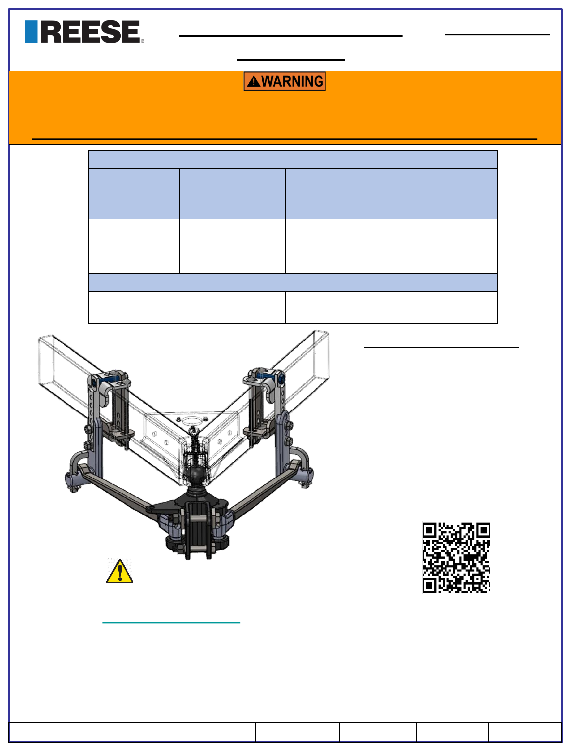
Experience the ultimate in sway control and weight distribution. The Dual Cam II, High Performance System
continually works to ensure the highest level of towing safety. The stronger the sway force, the more the
Dual Cam II System works to stop it. It’s the difference between active sway and passive sway control
where our unique design literally forces the trailer to stay in a straight line behind the tow vehicle. The newly
redesigned Dual Cam II system is now easier than ever to install and offers even broader application
coverage to work with the most popular trailer frames.
➢Fully automatic, active sway control system forces trailer to stay straight behind tow vehicle
➢No Drill installation
➢No need to relocate items on top of A-Frame to install Dual Cam II High-Performance Sway Control
➢Simple installation and adjustment
➢Hooking up spring bars automatically hooks up sway control
➢No U-bolts to interfere with bottle racks or another A-Frame mounted items
➢Limited lifetime warranty
➢Reduced noise when traveling
➢Rated for weight carry of 10,000 lbs
➢Includes pre-torqued 2-5/16” hitch ball
➢Works with both 1-1/2” and 2” frame widths
➢Works with frame heights of 4”-7”
Frequently asked questions:
➢What is a Weight Distribution Kit / Hitch?
Ans: Weight distribution kit or hitch is a system where it acts as a leverage between the tow vehicle & the
trailer causing the Tongue weight to be carried by all axles of the tow vehicle & trailer.
➢What is Gross trailer weight , Tongue weight & FALR?
Ans: Gross trailer Weight: Weight of a fully loaded trailer, inclusive of cargo.
Tongue Weight: The downward force that is exerted on the hitch ball by the trailer coupler.
FALR: Front Axle Load Restoration
➢Is a Sway Bar needed with this kit?
Ans: The kit is built in with a Sway prevention. Sway bars are not required.
➢Can the Kit be used on an Aluminum trailer?
Ans: Yes, the kit can be installed on an aluminum trailer. However, an Isolator shall be used to avoid
Galvanic corrosion. Polypropylene tape or a heavy-duty Packaging tape maybe used as an Isolator.
➢Can a lower rating Spring bars be used to tow higher load?
Ans: No, Higher loads cannot be towed with a lower rated Spring Bars.
©2022 Horizon Global America Inc. Page 2 of 16 66091N 02/03/2022 Rev. E

Installation Instructions
Dual Cam II Part Number(s):
66091, 66092, 66093
BALL MOUNT ASSEMBLY
CAM & BRACKETASSEMBLY
©2022 Horizon Global America Inc. Page 3 of 16 66091N 02/03/2022 Rev. E

Installation Instructions
Dual Cam II Part Number(s):
66091, 66092, 66093
BALLMOUNT . QTY -1
1 2 3 4
567
8
ADJUSTABLE WASHERS.
QTY -2
HEX BOLT: ¾” 10x 5-1/2” .
QTY -1
HEX BOLT: ¾” 10x 4-1/2” .
QTY -1
HEX NUT: ¾” -10. QTY -2
LOCK WASHER: ¾”.
QTY -2
SPRING BARS: 600lbs FOR WD KIT No: 66091. QTY-2
SPRING BARS: 800lbs FOR WD KIT No: 66092.. QTY-2
SPRING BARS: 1,200lbs FOR WD KIT No: 66093. QTY-2
BALLMOUNT SPACER .
QTY -1 UPPER CAM WELDMENT.
QTY -2 INNER BRACKET.
QTY -2
910 11
HEX BOLT: 5/8” 11x 4” .
QTY -2
12
HEX LOCK NUT: 5/8”-11.
QTY -2
13
LOWER CAM WELDMENT.
QTY -2
14
HEX BOLT: 5/8” 11x 3-1/2” . QTY -2 ( FOR 2” FRAMES)
HEX BOLT: 5/8” 11x 3” . QTY -2 ( FOR 1-1/2” FRAMES)
©2022 Horizon Global America Inc. Page 4 of 16 66091N 02/03/2022 Rev. E

Installation Instructions
Dual Cam II Part Number(s):
66091, 66092, 66093
CONICAL WASHERS: 5/8 .
QTY -2
15 16 17
18 19
21
BOLT ON CAM. QTY -2
HEX NUT: ½ ” -13. QTY -4
22 23
LYNCH PIN . QTY -2
CARRIAGE BOLT: ½” – 13X 8-1/2” . QTY -4 CONICAL WASHERS: ½” .
QTY -4
HEX BOLT: 5/8” 11x 1-1/4” .
QTY -4
LOCK WASHER: 5/8”.
QTY -4
BAR RETAINER. QTY -2
20
REQUIRED TOOLS
•1-1/8” SOCKET
•1-1/8” WRENCH
• 15/16” SOCKET
• 15/16” WRENCH
• 3/4” SOCKET
• 3/4” WRENCH
•TORQUE WRENCH: UP-TO 450 ft-lbs
•TAPE MEASURE
24
SPRING BAR LEVER QTY -1
©2022 Horizon Global America Inc. Page 5 of 16 66091N 02/03/2022 Rev. E

Failure to read warnings and follow instructions may result in serious personal injury or death, vehicle crash, and/or property
damage.
•Do not modify.
•Do not tow one trailer behind another (Tandem Towing).
Avoid putting any part of your body under the trailer or between the truck and trailer. Unexpected or accidental movement of
the truck or the trailer can cause serious injury or death
If you must place any part of your body under the trailer or between the truck and trailer you MUST perform ALL the following
steps:
•Check that the truck transmission is in park
•Check that the emergency brake is set
•Block in front of and behind all trailer tires
•Check that the trailer landing gear are resting on firm ground
Hitch balls may have reduced load rating. Ball rating must equal or exceed trailer GVWR.
Installation Instructions
Dual-Cam II Part Number(s):
66091, 66092, 66093
Assembly and Installation
INITIAL SET-UP: BALL MOUNT
1. .
2.
3.
➢Line up tow vehicle and trailer on level pavement, in a
straight line, uncoupled.
➢Make sure trailer is level both sides (Front to Back)
➢To achieve proper Weight Distribution, Measure the height
of the front truck fender to the ground and record that
height.
Note:
If the truck is equipped with Air Bags, It may be necessary to
turn off the system & wait for 20 minutes to make sure the air
bags are deflated. Please refer to your vehicle’s owner’s manual
for proper towing before Installation. Weight Distribution
between the truck & trailer may be improper if the air bags
deflate instructions are not followed.
➢Install the appropriate Hitch Bar (Not provided with the Kit) in
the truck receiver, and secure with the hitch bar pull pin &
retainer clip (Not provided with the kit). Depending on the
towing setup the Hitch Bar can be used in Rise or Drop
position.
Note: Dual Cam II WD Kit does not include Hitch Bar. Reese
part number: 3357 ( 2-Inch Hitch Bar) is shown in the picture
as reference.
©2022 Horizon Global America Inc. Page 6 of 16 66091N 02/03/2022 Rev. E

Pre-Assembled Ball
(Torqued to 450 ft-lbs)
Ball must be torqued to 450 ft-lbs.
Please check before each use.
!
➢Insert the 5-1/2” long bolt (2) through the
adjustment washer (3), the ball mount (1), the
hitch bar, the second adjustment washer (3),
lock washer (4), and nut (5). Also insert the
bottom 4-1/2” bolt (6) through the ball mount
(1), the shank, lock washer (4), and nut (5).The
adjustment washers and ball mount slot allow
for up to 15⁰ of adjustment . Hand tighten
Upper & lower nuts onto bolt.
➢Coupler’s Height adjustment:-
Level the trailer. Measure & record the
distance from the ground to the top of the
coupler ball socket.
THE HEIGHT OF THE HITCH BALL NEEDS TO BE ~1 INCH ABOVE THE
COUPLER. THIS IS TO COMPENSATE FOR VEHICLE SQUAT WHEN
THE TRUCK & TRAILER ARE CONNECTED
➢Slide the Ball mount (1) from the top or bottom of
the Hitch Bar, aligning the holes until the top of
the Ball is ~1 from the top of coupler
•Note: If needed fill any gap between the Ball
mount (1) & the Hitch Bar with a Ball mount spacer
provided (8).
•This kit comes with a 2-5/16” ball pre-assembled
on the Ball mount. Confirm that the trailer coupler
is 2-5/16” or replace the hitch ball on the ball
mount. This ball mount requires a ball with a 1-1/4”
shank thread size.
Installation Instructions
Dual-Cam II Part Number(s):
66091, 66092, 66093
4.
5.
©2022 Horizon Global America Inc. Page 7 of 16 66091N 02/03/2022 Rev. E

6.
7.
8.
➢Install Spring Bars (7) into Ball mount (1) by rotating
the bars horizontally, slipping the lower trunnion
posts into the pockets, then rotating the bars into
position parallel to trailer frame rails
Note: Height of the Coupler may vary based on
the type of the couplers.
➢Ensure the adjustment washers are in the same tooth
position on either side of the ball mount by counting the
number of exposed teeth on either side. Washer teeth
must be parallel to ball mount teeth for proper
engagement. Secure the ball mount pitch by tightening
the top bolt to 300 ft-lbs of torque. Then tighten the
bottom bolt to 300 ft-lbs of torque
Note: At max tilt adjustment of the ball mount (1) not all
teeth on the adjustment washers may mate to all teeth on
the ball mount .This may be a common scenario.
Installation Instructions
Dual-Cam II Part Number(s):
66091, 66092, 66093
➢Manually lift the bars until the Ball mount aligns
straight up to the upright position.
➢Note the tooth position of the adjustment washers
on the Ball mount when the Spring bars are lifted to
the max height. This should be the positioned where
the adjustment washers need to be tightened to
achieve the proper Ball mount angle.
➢Make sure that the hitch ball is ~1” above the
trailer's coupler
!
©2022 Horizon Global America Inc. Page 8 of 16 66091N 02/03/2022 Rev. E

9.
10.
11.
➢For proper bracket positioning, couple the trailer to the
truck. Make sure to secure the coupler on to the ball
mount with the lock.
➢Reinstall the Spring Bars
➢Using Brackets fastener kit . For one side of the trailer,
loosely assemble, Upper Cam Weldment (9), inner
frame bracket (10) upper bracket hex bolt (11)(4” long
for 2” wide frames 3-1/2” long for 1-1/2” wide frames,),
and lock nut (12).
➢Slip brackets over the trailer frame so that the center
of the brackets is in line with center of the convex
portion of the Cam (19) in the Spring Bars as shown
in the picture.
➢Repeat the step on the other side of the trailer frame.
Installation Instructions
Dual-Cam II Part Number(s):
66091, 66092, 66093
©2022 Horizon Global America Inc. Page 9 of 16 66091N 02/03/2022 Rev. E

12.
13.
➢Slide the lower frame bracket (13) around the inner
frame bracket (10), between the outside of the
trailer frame and the outer frame bracket as shown
in picture. Secure the lower bracket with the
appropriate lower bracket bolt (14)(3” long for 1-1/2”
wide frames, 3-1/2” long for 2” wide frames) &
conical washer (15).
➢Partially tighten upper (11) and lower bracket
bolts(14) until both brackets become flush with
inside and outside surfaces of the trailer frame.
Allow for some sliding to position the brackets and
cam correctly for the spring bars to rest on the Cam.
➢Repeat the step on the other side of the trailer
frame.
Installation Instructions
Dual-Cam II Part Number(s):
66091, 66092, 66093
➢Select carriage bolts (16) , ½” nuts (18) and ½”
washers (17). Slide in the carriage bolts through
the upper cam weldment (9) as shown. Bolts shall
pass through the square holes of the lower cam
(13). Install the fasteners as closely to the frame
as possible. Tighten bolts and nuts until the lower
frame bracket is held securely against the bottom
of the frame.
➢Do not fully torque the carriage bolts. Allow for
some sliding of the assembly brackets to position
the brackets correctly so that the spring bars shall
align on to the Cam.
➢Repeat the step on the other side of the trailer
frame.
©2022 Horizon Global America Inc. Page 10 of 16 66091N 02/03/2022 Rev. E

14.
Installation Instructions
Dual-Cam II Part Number(s):
66091, 66092, 66093
➢Slide Cam (19) over Upper Cam Weldment (9). Position the bottom of the Cam (19) surface ~
4” above the top of the spring bar surface.
➢Bolt the cam in position using the 5/8” bolts (21) and lock washers (20).
➢Ensure bolts do not use the same threaded hole as the lower frame bolt. Cam bolts
may have either 1 or 2 open holes between then. Both bolts need to be installed in
threaded holes
➢Torque both the Carriage Bolt (16) fasteners to 130 ft-lbs.
➢Torque both the Cam (19) fasteners to 100 ft-lbs.
➢Repeat the step on the other side of the trailer frame.
!
!
©2022 Horizon Global America Inc. Page 11 of 16 66091N 02/03/2022 Rev. E

15.
16.
Installation Instructions
Dual-Cam II Part Number(s):
66091, 66092, 66093
➢With the trailer coupled to the Ball mount, use the trailer jack
to lower the trailer to remove the load on the spring bars so
that the spring bars can be swung on top of the cams without
any excessive force. Sometimes a block may be required
under the jack to get the required jack extension length.
➢With the Spring bars being loaded & installed over the Cam,
use the trailer jack to raise the trailer to its original position.
➢Install the spring bar retainer (22) and secure it with
Lynch pin (23).
➢Repeat the step on the other side of the trailer
frame.
Note: (Raise up the jack)
➢Remeasure the distance between the Fender & the ground to make sure the weight is evenly
distributed. The measurement needs to be the same as measured before installing the Weight
Distribution system.
➢In case of Higher measurements: The Front Axle Load may be lower. Which says the system needs
additional weight distribution loads. This could be done by adjusting the Cam hole position. Raise
the Cam by one bolt hole to restore the Front Axle Load.
➢In case of Lower measurements: The Front Axle Load may be higher. To lower the front axle load,
lower the Cam by one bolt hole & fasten the bolts.
➢Please make sure to double check all the bolts of the system are securely fastened
Note:
In some applications the trailer jacks may not available or
could not be used. In such cases, Springs bars shall be
installed manually using the spring bar lever (24). Extreme
caution needs to be followed while installing the Spring
bars.
Lynch Pin Orientation:
©2022 Horizon Global America Inc. Page 12 of 16 66091N 02/03/2022 Rev. E

Installation Instructions
Dual-Cam II Part Number(s):
66091, 66092, 66093
OPTIONAL BALLMOUNT SPACER KIT
Use the Ball mount spacer provided when needed to fill any gap between the ball mount and shank.
It is easier to install the shim from the top. In doing so, you will encounter one of three scenarios:
a. Ball mount spacer will align with both holes. If this is the case, use the entire spacer in the gap.
NOTE: It is conceivable in rare combinations, two spacers could be used. In these cases, contact
Customer Service at 800-632-3290 for a free additional spacer service kit part number 58207.
a. Ball mount spacer will not fit between the ball mount and shank. In this case, discard the spacer and
continue with installation.
b. Spacer will not go in far enough to reach both holes. In this case, cut shim in half and use only the top
half of the spacer for the top bolt hole. Discard the cut spacer remnants.
INITIAL SET-UP: Measurement and adjustment
➢After reviewing all fasteners and brackets, ensuring spring bars are properly seated in the ball mount
and on the cam brackets, retract the trailer jack until the jack foot plate lifts off the ground.
➢Measure the same truck fender location measured in Step 1 Initial Set-up: Ball Mount. If the fender
height is:
a. Higher than unloaded: Increase front axle load restoration by raising the cams (19) one bolt
hole or adjusting the ball mount (1) so that the spring bar cam ends are lower.
b. Lower than unloaded: Decrease front axle load restoration by lowering the cams (19) one bolt
hole or adjusting the ball mount (1) so that the spring bar cam ends are higher.
➢LOADED BALL HEIGHT SHOULD NEVER BE GREATER THAN UNCOUPLED BALL HEIGHT.
Front wheel overload and loss of rear wheel traction can result, and can lead to unstable
handling, reduced braking ability, and a tendency to "jackknife" when turning and braking at
the same time.
➢IF LOADED BALL HEIGHT IS GREATER THAN UNCOUPLED HEIGHT, reduce take-up on
spring bars and re-measure until proper height is obtained. When backing trailers in tight
areas use caution not to jackknife trailer or similar conditions. Trunnion bars swing left and
right a limited amount and can damage ball mounts if over rotated (remove if necessary)
!
Maintenance Recommendations:
➢Trunnions, Ball & Cam (Spring bar & Cam interface) shall be lubricated the first 250 miles
with lithium grease or heavy oil. Make sure to wipe clean the rag before lubricating. This
allows the bars to “embed” properly in the cams.
➢Its also recommended to mark the spring bars so you know which one is the driver’s side
or passenger side. Switching sides with the bars every trip is not recommended and can
cause excessive noise.
Note:
➢Metal to metal contact may result in noises, especially at slower speeds.
➢Spring bars & Cams are not expected to be at the same angle.
➢Springs bars may not necessarily sit flat on the Cams.
©2022 Horizon Global America Inc. Page 13 of 16 66091N 02/03/2022 Rev. E

➢DO NOT TOW MULTIPLE TRAILERS:
Do not attempt to tow any type of trailer behind another trailer. Towing multiple trailers may cause
severe instability, loss of control and/or structural failure, and may result in vehicle accident,
property damage and personal injury. Towing multiple trailers is illegal in many jurisdictions.
➢MAINTENANCE BEFORE EVERY TRIP:
Keep trunnions and sockets in head assembly free of dirt/debris and well lubricated. Excessive
wear in this area may indicate overload or inadequate lubrication. Some elongation of socket
openings ("seat in“) is normal.
•Keep head assembly exterior clean, especially the trunnion sockets. Do not allow dirt or debris to
lodge between trunnions and head.
•Keep hitch painted to prevent rust and maintain a good appearance. (Do not paint over labels)
➢AT THE BEGINNING OF EVERY TRIP:
a) Clean ball and coupler socket and coat ball lightly with grease.
b) Check spring bars and bolts for wear. Replace any component before becoming worn halfway
through.
c) Check to see that all bolts are properly tightened, and hitch pin and clip are securely in place.
d) Check to see that electrical hookups are in working order, and that safety chains are securely
connected.
TOWING TIPS
➢DRIVING: Good habits for normal driving need extra emphasis when towing. The additional weight
affects acceleration and braking, and extra time should be allowed for passing, stopping, and
changing lanes. Signal well in advance of a maneuver to let other drivers know your intentions.
Severe bumps and badly undulating roads can damage your towing vehicle, hitch, and trailer, and
should be negotiated at a slow steady speed. IF ANY PART OF YOUR TOWING SYSTEM
"BOTTOMS" OUT, OR IF YOU SUSPECT DAMAGE MAY HAVE OCCURED IN ANY OTHER WAY,
PULL OVER AND MAKE A THOROUGH INSPECTION. CORRECTANY PROBLEMS BEFORE
RESUMING TRAVEL.
➢CHECK YOUR EQUIPMENT: Periodically check the condition of all your towing equipment and
keep it in top condition.
IMPORTANT INFORMATION ON TOWING
Failure to heed warnings and follow instructions may result in serious personal injury or
death, vehicle crash, and/or property damage.
➢Do not modify.
➢Do not tow one trailer behind another (Tandem Towing).
!
Installation Instructions
Dual-Cam II Part Number(s):
66091, 66092, 66093
©2022 Horizon Global America Inc. Page 14 of 16 66091N 02/03/2022 Rev. E

➢TRAILER LOADING:
Proper trailer loading is important. Heavy items should be placed close to the floor near the trailer
axle. The load should be balanced side-to-side and firmly secured to prevent shifting. Tongue
weight should be about 10-15 percent of the gross trailer weight for most trailers. Too low a
percentage of tongue weight will often produce a tendency to sway. Excess weight on the tongue
can also lead to sway and damage hitch and/or tow vehicle.
➢TIRE INFLATION:
Unless specified otherwise by the towing vehicle or trailer manufacturer, tires should be inflated to
their maximum recommended pressure.
➢TOWING VEHICLE AND TRAILER MANUFACTURER’S RECOMMENDATIONS: Review the
owner’s manual for your towing vehicle and trailer for specific recommendations, capacities, and
requirements.
➢POLE (STRAIGHT) TONGUE TRAILERS:
If your trailer has a straight tongue (instead of an A-frame tongue), it will be necessary to use a pole
tongue adapter. This adapter attaches to the trailer tongue, providing a place to attach the
bracketry.
➢PASSENGERS IN TRAILERS:
Trailers should NOT be occupied while being towed, under any circumstances.
➢TRAILER LIGHTS, TURN SIGNALS, AND ELECTRIC BRAKES:
Always hook up trailer lights, turn signals, electric brakes and break-away switch connection (if
equipped) even for short trips.
➢REMOVE SPRING BARS WHEN BACKING UP:
It is recommended to remove the spring bars while backing up into campsites, driveways, etc.
➢REMOVE HITCH WHEN NOT TOWING:
Remove hitch from towing vehicle receiver when not towing, to prevent contamination of head
sockets, reduce chance of striking hitch on driveway ramps or other objects, and minimize damage
in the event of a rear-end collision.
IMPORTANT INFORMATION ON TOWING
Installation Instructions
Dual-Cam II Part Number(s):
66091, 66092, 66093
©2022 Horizon Global America Inc. Page 15 of 16 66091N 02/03/2022 Rev. E

Part Number Purchased:
Place of Purchase:
Date of Purchase:
Part Manufactured Date (located on the ball mount):
Product Instructions:
Dual-Cam II
NOTES:
Horizon GlobalAmerica, Inc
47912 Halyard Drive Suite 100
Plymouth, MI 48170
LIMITED LIFETIME WARRANTY
1. Limited Lifetime Warranty (“Warranty”). Horizon Global (“We” or “Us”) warrants to the original
consumer purchaser only (“You”) that the product will be free from material defects in both material and
workmanship for a period of lifetime of ownership, ordinary wear and tear excepted; provided that
installation and use of the product is in accordance with product instructions. There are no other
warranties, express or implied, including the warranty of merchantability or fitness for a particular
purpose. This warranty is not transferable.
2. Limitations on the Warranty. This Warranty does not cover: (a) normal wear and tear; (b) damage
through abuse, neglect, misuse, or as a result of any accident or in any other manner; (c) damage from
misapplication, overloading, or improper installation; (d) improper maintenance and repair; and (e)
product alteration in any manner by anyone other than Us, with the sole exception of alterations made
pursuant to product instructions and in a workmanlike manner.
3. Obligations of Purchaser. To make a Warranty claim, contact Us at 47912 Halyard Drive Suite 100,
Plymouth, MI, 48170, 1-800-632-3290, identify the product by model number, and follow the claim
instructions that will be provided. Any returned product that is replaced by Us becomes our property.
You will be responsible for return shipping costs. Please retain your purchase receipt to verify date of
purchase and that You are the original consumer purchaser. The product and the purchase receipt must
be provided to Us in order to process Your warranty claim.
4. Remedy Limits. Product replacement is Your sole remedy under this Warranty. We shall not be liable
for service or labor charges incurred in removing or replacing a product or any incidental or
consequential damages of any kind.
5. Assumption of Risk. You acknowledge and agree that any use of the product for any purpose other
than the specified use(s) stated in the product instructions is at Your own risk.
6. Governing Law. This Warranty gives You specific legal rights, and You also may have other rights
which vary from state to state. This Warranty is governed by the laws of the State of Michigan, without
regard to rules pertaining to conflicts of law. The state courts located in Oakland County; Michigan shall
have exclusive jurisdiction for any disputes relating to this Warranty.
Product Registration:
www.reeseprod.com/support/products/registration
©2022 Horizon Global America Inc. Page 16 of 16 66091N 02/03/2022 Rev. E
This manual suits for next models
3
Table of contents
Other Reese Automobile Accessories manuals

Reese
Reese Sidewinder 61302 User manual

Reese
Reese TransRACK 70552 User manual

Reese
Reese 50026 User manual

Reese
Reese 30054 User manual

Reese
Reese M5 User manual

Reese
Reese 30886 User manual

Reese
Reese Elite Series User manual

Reese
Reese SWAY CONTROL User manual

Reese
Reese 56011 User manual

Reese
Reese Revolution 86016 User manual
Popular Automobile Accessories manuals by other brands

LSD-Doors
LSD-Doors 50025002 Installation instructions manual

Cruz
Cruz Evo Rack Module E37 Assembly instructions

Metra Electronics
Metra Electronics 88-00-3302 installation instructions

DV8
DV8 LBBR-01 installation manual

Warn
Warn 103638 installation instructions

WeatherTech
WeatherTech No-Drill MudFlap installation instructions