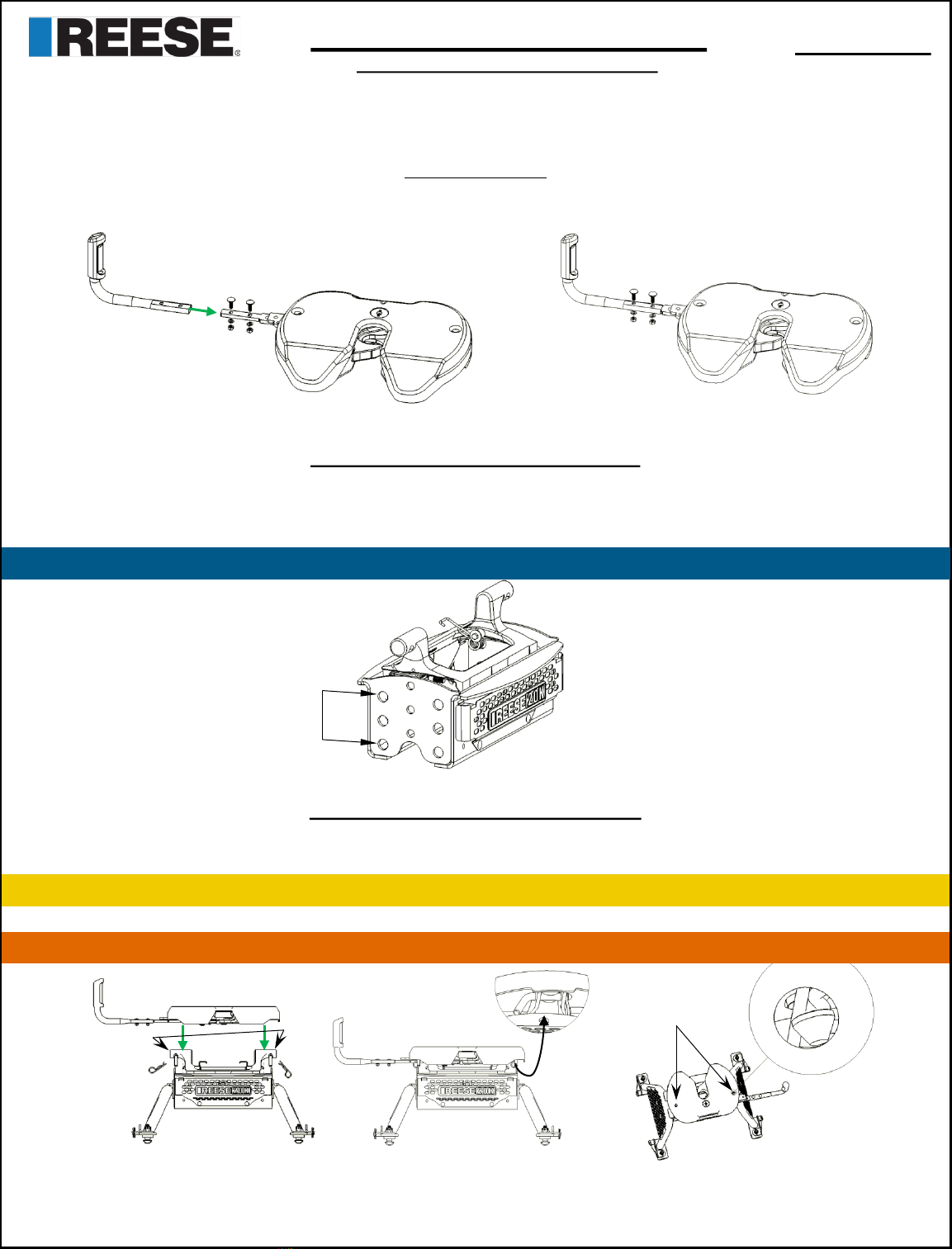
M5 HEAD & CENTER SECTION Part Number:
30892 & 30884
FOR INSTALLATION WITH
M5 MOUNTING LEGS HITCHING PROCEDURE
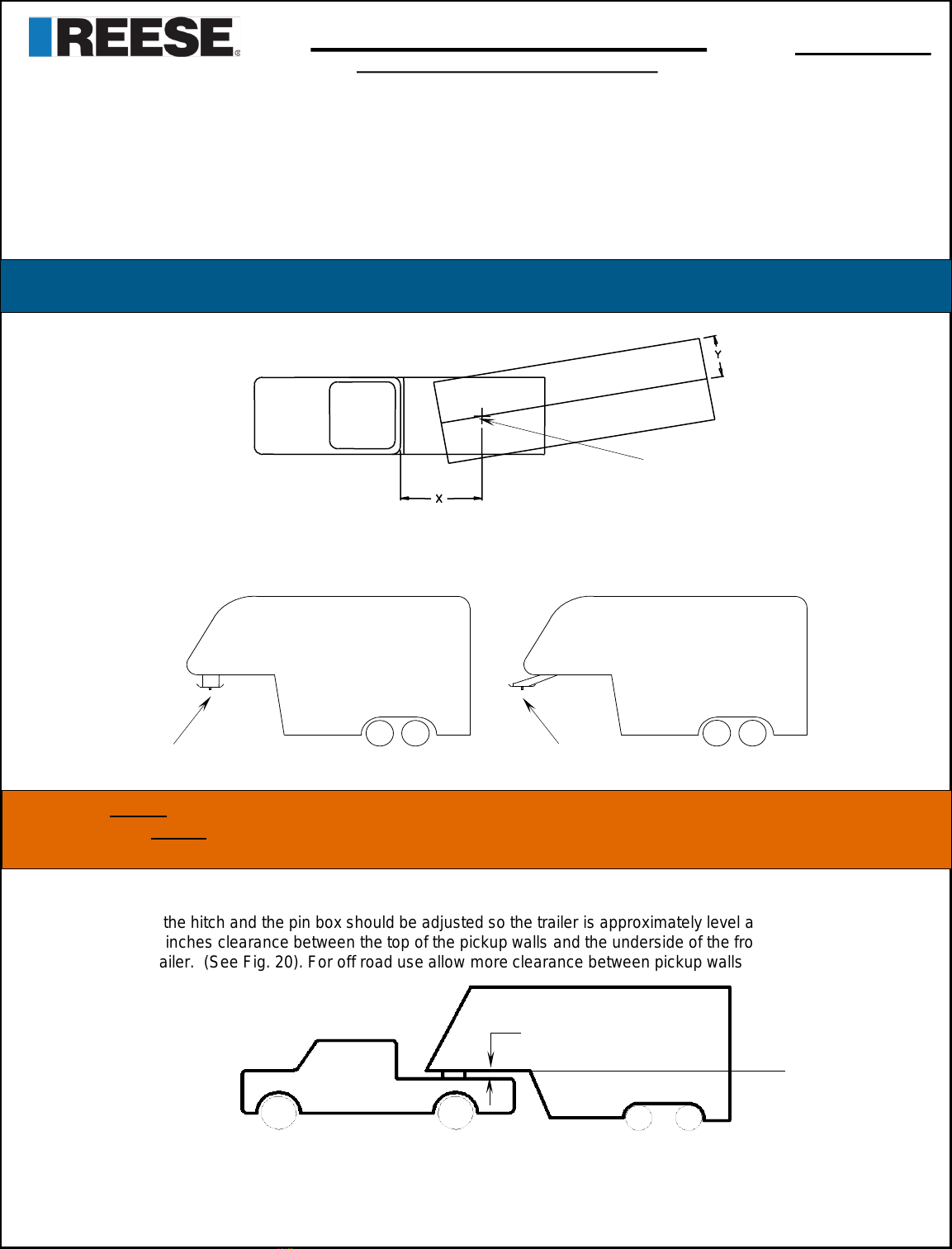
Before hitching to a trailer, make sure your 5th wheel hitch height is correct. Guidelines on how to properly set the
height of your 5th wheel hitch can be found in the on page 5.
1. Make sure the truck and trailer are in position to couple
A. 5th wheel hitch is correctly secured to truck
B. Truck tailgate is lowered if necessary
C. Blocks/Chocks are firmly against each trailer wheel to prevent any possible forward or rearward motion.
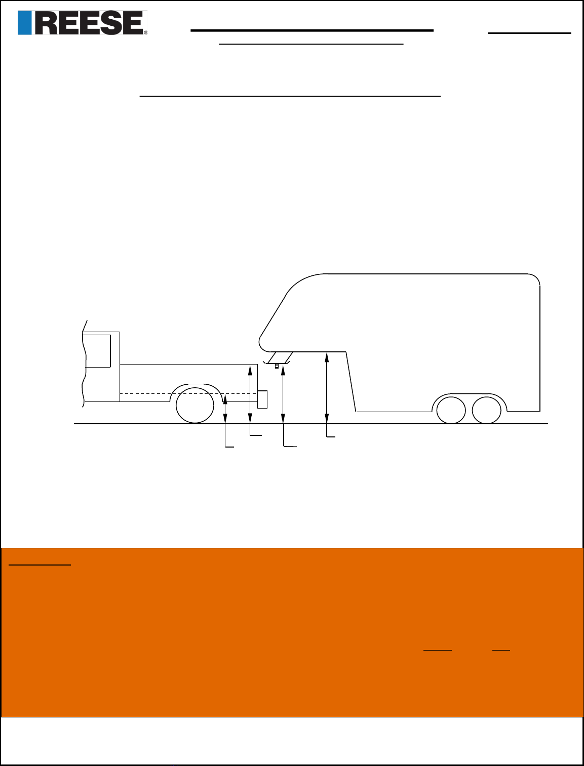
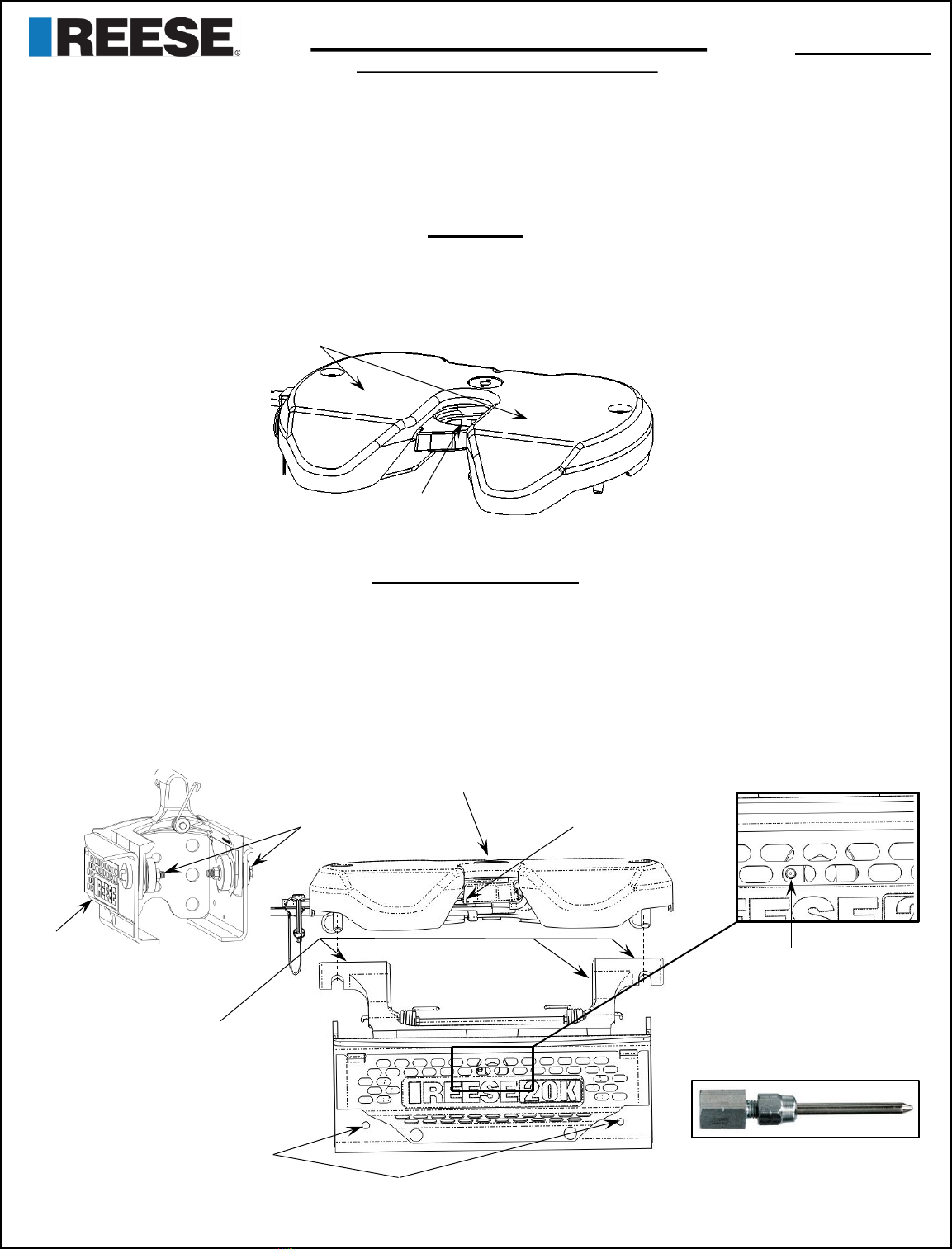
D. Pin box is at correct height for hitching (fig. 13 & 14).
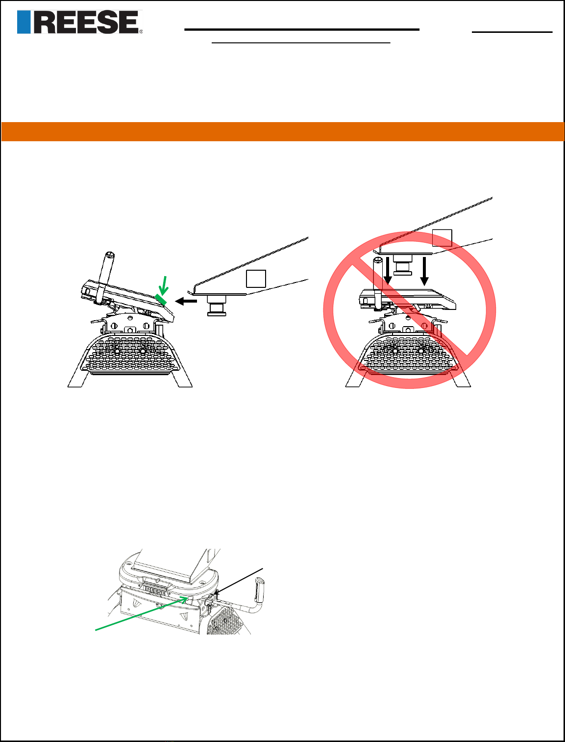
E. Make sure head is in Ready-to-Receive position (pg. 4, fig.10)
2. Back truck slowly into trailer so the trailer king pin and 5th wheel funnel align. Hitch will latch automatically when truck is
backed completely into trailer king pin. When this occurs, the indicator will be 100% green (pg. 4, fig. 11).*
3. Perform Pull Test
A. With trailer wheels still firmly blocked, trailer landing gears firmly on the ground supporting trailer weight, and trailer
brake on, make sure no one is between the truck and trailer.
B. Try to pull trailer slowly forward. If trailer is properly hitched, proceed to Step 4. If trailer is not properly hitched,
trailer will separate from hitch, and truck will move forward - Repeat steps 1 thru 3.
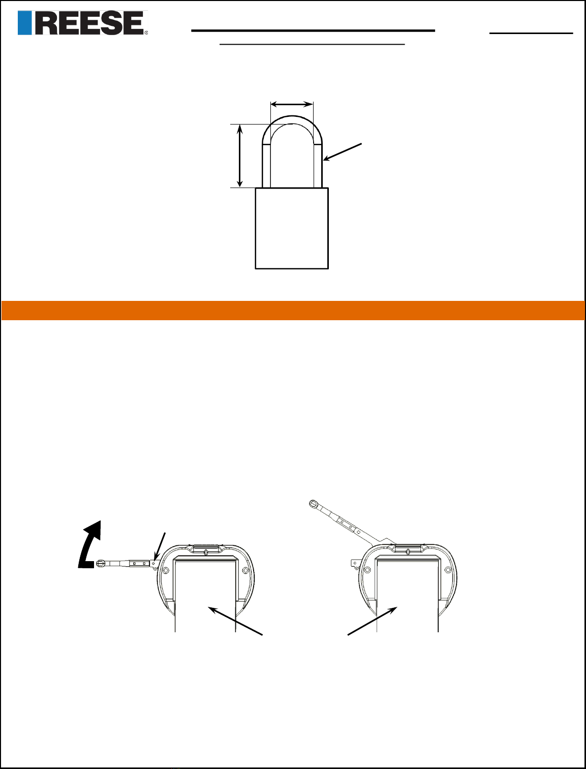
4. Insert bail pin into bail pin hole, as shown in figure 15, or lock for added security. Possible lock dimensions shown on
page 10.
1. Connect electrical cable and breakaway switch cable between truck and trailer, raise tailgate as necessary.
2. Remove chocks/blocks and lift trailer jacks.
*Jaw may not close if it is under high compression load. If fully backed into trailer and not fully latched, pull truck slightly forward to remove load on jaw.
Handle will latch automatically.
FIG. 13 FIG. 14
Bottom of Pin Box to be
0 to 2 inches below top of
Skid Plate ramp
Bail pin shown in the inserted & latched position
FIG. 15
CONTACT ZONE
0-2”below top of skid
plate ramp
Indicator shows
Green
WARNING: Failure to follow these instructions may result in property damage, serious injury, or death.
Installation Instructions