Le istruzioni sono fondamentali per il corretto uso e funzionamento dell’apparecchio;
pertanto devono essere accuratamente conservate anche dopo l’installazione, per ogni
futura consultazione.
NOTE GENERALI
• Conformità: Norme Europee EN 60598-1:2008+A11:2009, EN 60598-2-2/A1 e EN
60598-2-22/A2 (per gli apparecchi in emergenza), Direttive comunitarie BT 2006/95/CE
EMC 2004/108/CE.
• La linea di prodotti SUPERTECHNE è costituita da apparecchi da incasso
esclusivamente per ambienti interni o aventi vano d’incasso asciutto, privo di acidi, olii
e grasso.
• Il grado di protezione degli apparecchi si differenzia tra quelli:
con vetro di protezione e flangia continua IP44 (parte esposta)
e IP20 (parte incassata);
privi di vetro o con vetro di protezione e flangia areata IP23 (parte esposta)
e IP20 (parte incassata).
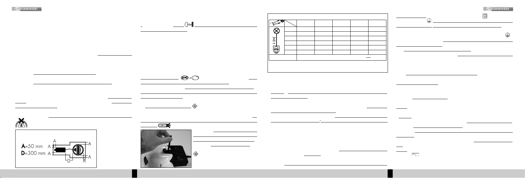
• Tutti gli apparecchi della linea SUPERTECHNE sono idonei al montaggio diretto su
superfici normalmente infiammabili. In particolare, come per tutti
gli apparecchi da
incasso,
è importante verificare che le pareti laterali dell’apparecchio
distino almeno
50mm dalle pareti dell’incasso,
mentre la parte superiore può essere a diretto contatto
con materiali normalmente infiammabili; montare il distanziale fornito a corredo ove
previsto (fig.
), ma in
nessun caso, dovranno essere coperti con materiale isolante.
Il gruppo separato di
alimentazione, deve
essere posto a lato ad
una distanza minima di
300mm dall’apparecchio
e ad almeno 50mm dalla
parete laterale
dell’incasso, il
cavo di
quest’ultimo (Tipo Y) in caso di danneggiamento dovra essere sostituito dalla Reggiani
SpA o dal suo servizio di assistenza o da personale qualificato (fig.
).
•
Il
numero racchiuso nel
simbolo indica -in metri- la distanza minima alla quale
va posto l’oggetto da illuminare;
tale distanza viene misurata lungo l’asse ottico
dell’apparecchio, dalla parte della lampada all’oggetto illuminato più vicino. Gli
oggetti fotosensibili, se esposti all’azione dei raggi solari o di sorgenti di luce
artificiale possono scolorire. Al fine di aumentare la sicurezza ed il tempo di
esposizione è consigliabile utilizzare lampadine a limitata emissione di raggi UV, le
così dette UV-STOP.
Attenzione: l’efficacia del filtro anti-UV è subordinata al livello dell’illuminamento
(Lux), alla distanza della sorgente luminosa, alla durata dell’esposizione ed alla
fotosensibilità dei singoli oggetti. La REGGIANI SPA ILLUMINAZIONE non si assume
alcuna responsabilità per eventuali deterioramenti degli oggetti esposti.
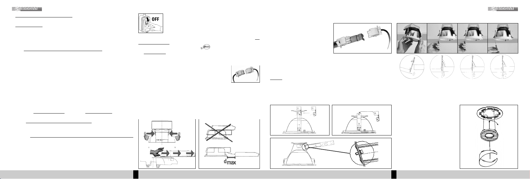
•
Gli schermi di sicurezza
se presenti sull’apparecchio,
vanno
tassativamente sostituiti in caso di danneggiamento o rottura,
prima di procedere
all’accensione dell’apparecchio,
richiedendoli alla REGGIANI SPA ILLUMINAZIONE.
Avvertenza: gli apparecchi possono essere utilizzati solo se completi dello schermo
di protezione dati in dotazione.
• Gli
apparecchi a bassissima tensione
(QR-CB) sono caratterizzati da elevatissime
correnti, si consiglia di consultare la tabella orientativa riportata (tabella
), prima di
procedere con l’installazione, per valutare la sezione dei cavi necessaria; inoltre,
per
il collegamento tra alimentatore e lampada, utilizzare cavi resistenti alle alte
temperature .
Attenzione:
la conformità alla norma è
garantita se e solo se l’apparecchio è
alimentato da un trasformatore di sicurezza,
o
equivalente,
conforme alle norme vigenti.
Gli apparecchi a bassissima tensione marcati
,
non devono essere collegati ai conduttori
di terra.
•
Il simbolo
indica che l’apparecchio è soggetto a tensioni di picco di 4,5kV in fase di
accensione della lampada.
Dunque è indispensabile prestare la massima attenzione
sia in fase d’installazione sia in fase di sostituzione della lampada, al fine di prevenire
qualsiasi rischio derivato dalla tensione d’alimentazione. In particolare
il collegamento
alla lampada, deve essere eseguito con cavi
resistenti ai picchi di tensione per
l’innesco lampada (4,5kV), con caratteristiche
non inferiori al tipo H05S-K (gomma
siliconica) e sezione max tra 1,5 mm
2
, con guaina esterna di protezione di Ø 8mm max,
rispettando le polarità previste, ovvero, il morsetto deve corrispondere al morsetto
LAMP del gruppo d’alimentazione.
Avvertenza: con lampada a fine vita, ovvero, al decadimento del flusso luminoso, è
doverosa la sostituzione della lampada stessa per prevenire gravi danni al gruppo
d’alimentazione, che potrebbero ripercuotersi sull’impianto tutto.
• Per un utilizzo ottimale delle lampade a scarica,
la variazione della tensione di rete
deve essere contenuta
entro +/-3%
dei valori nominali riportati sulle indicazioni di
targa.
• Utilizzare
per il cablaggio alla rete di alimentazione usare cavi flessibili con conduttori
in doppio isolamento,
bipolari per gli apparecchi in Classe II e tripolari per gli
apparecchi in Classe I ,
con caratteristiche non inferiori al tipo H07 RN F e sezione
compresa tra 1,5 e 2,5mm
2
, con guaina esterna di protezione di Ø 8 mm max.
• Altresì importante, rispettare le le polarità previste: Fase -polo F/L o morsetto 1-,
Neutro -polo N o morsetto 2- e, per gli apparecchi in Classe I, Terra -polo -
utilizzando il cavo giallo/verde.
A collegamento eseguito coprire i morsetti con
l’apposito coperchietto serracavo.
• Per il
cablaggio esterno degli apparecchi in emergenza,
nel caso in cui l’alimentazione
dell’apparecchio derivi da un sistema trifase,
è indispensabile utilizzare linee separate
di medesima fase. Altresì importante, rispettare le polarità previste: Fase Ordinaria -
morsetto 3-, Neutro Ordinario- morsetto N-; Fase Primaria -morsetto 2-, Neutro
Primario- morsetto 1-.
N. B.
La linea Primaria non deve essere mai interrotta,
se non volutamente per
operazioni di manutenzione.
±
Flusso luminoso in emergenza,
dopo 60 secondi dalla mancanza dell’alimentazione di
rete, per tutta la durata dell’autonomia, ~20% flusso lampadina in funzionamento
ordinario.
±Durata dell’
autonomia in emergenza:
2 ore per lampadine fino a 26W ed 1 ora per
lampadine 32/42W FSMH.
±
Batterie
: Ni/Cd max 50°C esenti da manutenzione; 3.6V - 4Ah per lampadine fino a
26W e 6V - 4Ah per lampadine 32/42W FSMH.
±Il
led verde
indica il normale funzionamento del circuito inverter – batteria;
±Negli apparecchi in emergenza bi-lampada, un
pallino verde sul portalampada
,
identifica la
lampadina del circuito d’emergenza.
±E’ opportuno
verificare semestralmente la funzionalità dell’impianto di illuminazione
di emergenza
ed effettuare una scarica completa delle batterie con successiva ricarica
per mantenerli in efficienza. Intervallo prudenziale per la
sostituzione delle batterie: 4
anni,
oppure in caso di mancato rispetto dell’autonomia.
±
Ricarica
: 24 ore.
• Il simbolo , specifico degli apparecchi con alimentatore elettronico, indica la
possibilità di alimentare l’apparecchio indifferentemente con corrente continua od
alternata, con valori di tensione compresi tra i 198V e 254V.
Tabella
DIMENSIONAMENTO CAVI
12 V = Wx1 24 V = Wx2 6 V = W:2
S= SEZIONE CONDUTTORI L= DISTANZA TRASFORMATORE: LAMPADA
1m
2m
4m
6m
8m
10 m
1.0 mm
2
120 W
80 W
40 W
25 W
20 W
15 W
AMPERE =W
V
LS1.5 mm
2
180 W
110 W
55 W
35 W
25 W
20 W
2.5 mm
2
240 W
200 W
140 W
65 W
50 W
40 W
4.0 mm
2
380 W
320 W
160 W
100 W
80 W
65 W
6.0 mm
2
550 W
500 W
250 W
160 W
120 W
100 W
SUPERTECHNE ITALIANO32
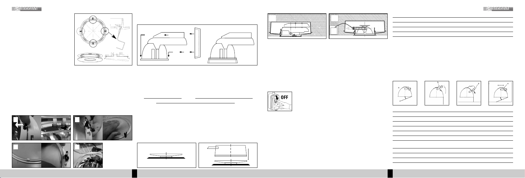
ISTRUZIONI DI MONTAGGIO SUPERTECHNE
Fig.
Fig.