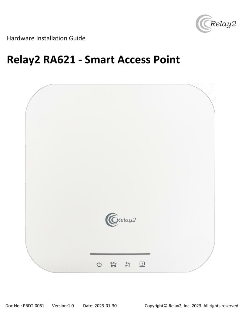
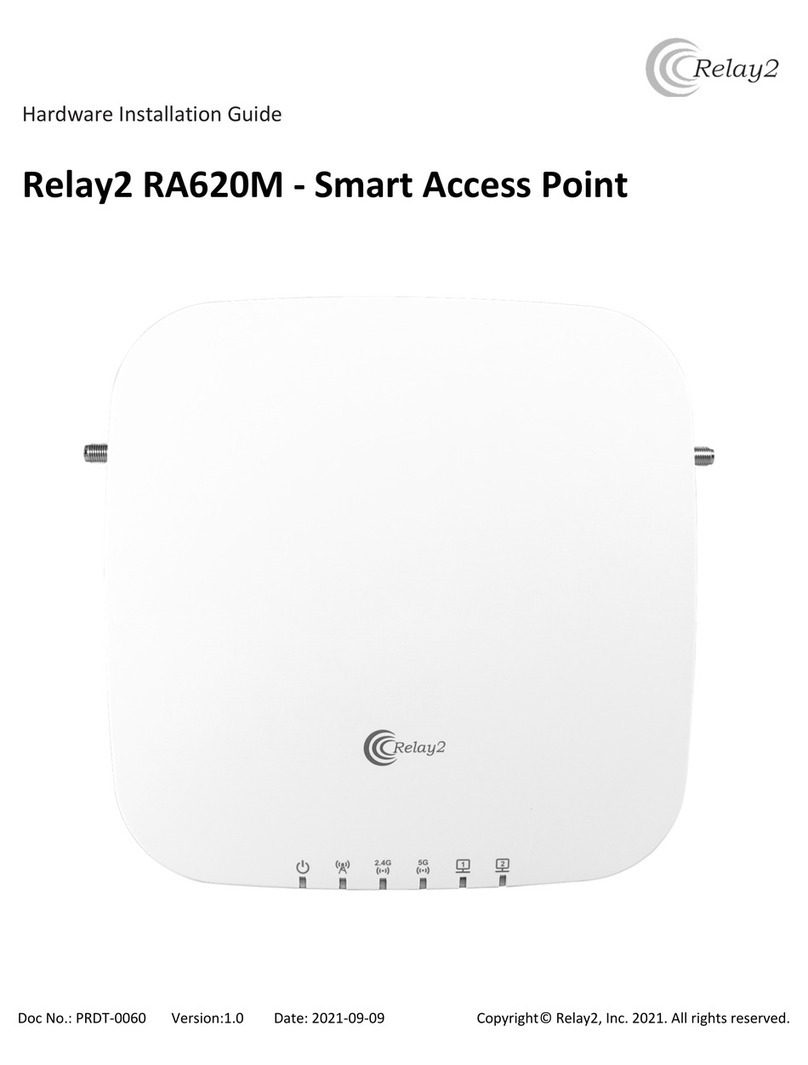
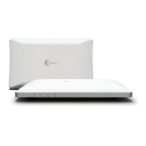
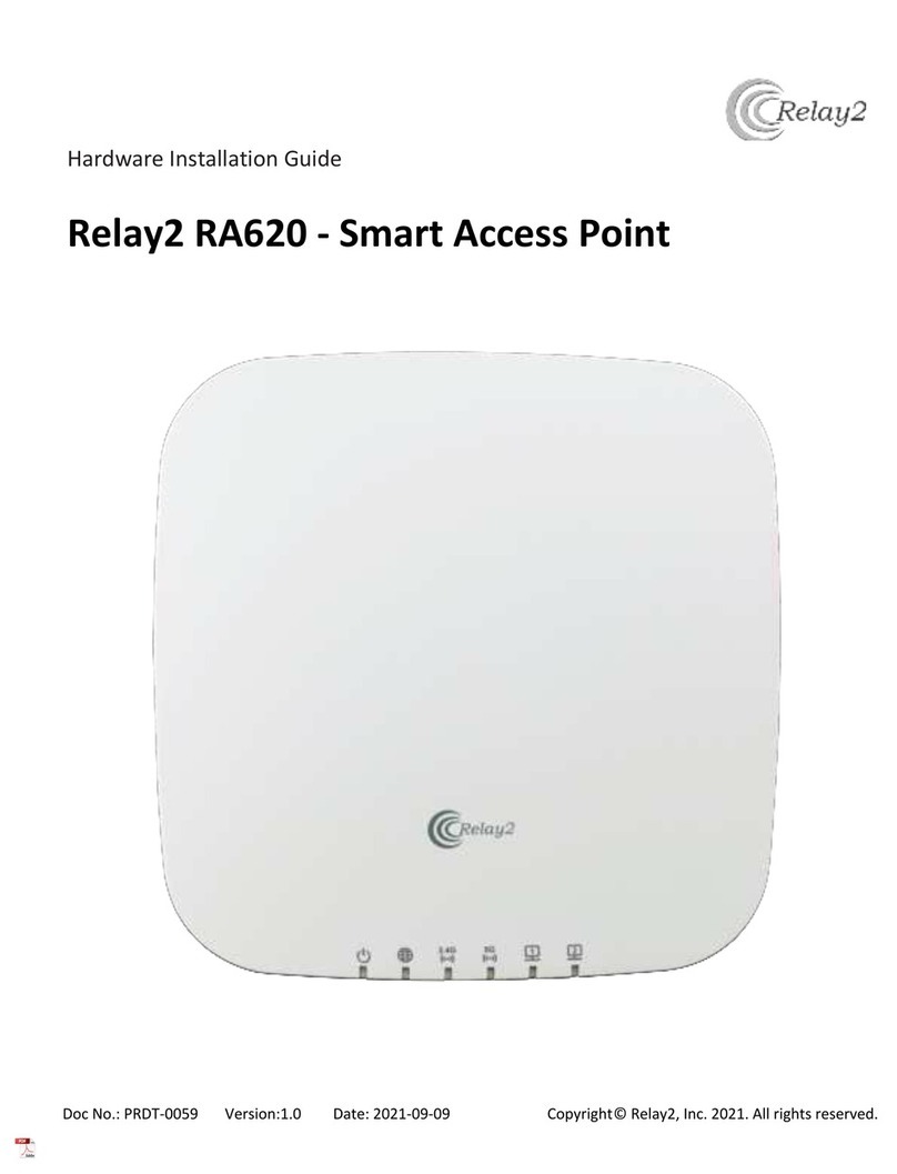
Relay2 RA621EX Manual

HARDWARE INSTALLATION GUIDE
RA621EX OUTDOOR SERVICE POINT
Doc No.: PRDT-0046 | Version 2.0 | Date 2023-12-13

RELAY2
TRADEMARKS
COMPANY HEADQUARTERS
The Relay2 logo is a trademark of Relay2, Inc.
of the US.
1525 McCarthy Boulevard, Suite 209
Milpitas, CA 95035, USA
www.relay2.com
+1 (408) 380-0031
PRODUCT OVERVIEW
The RA621EX is a cloud-managed Outdoor Service
Point, offering Edge Computing and storage
capabilities integrated with a high-performance
wireless access point. It enables businesses to
deliver superior venue experiences, enhance
business operations, and create competitive
advantages.
For more information about the RA621EX, please
refer to www.relay2.com.

Opening the Package
• Please ensure that all ordered optional
accessories are included in the separate
accessory box.
• Please peel off the protective lm before using
the AP.
• Please do not use a different power adapter
than the one included with the package.
• Please check the packaging list rst. If there are
any missing or broken parts, please contact
the authorized distributor of Relay2, Inc.
Warranty
• Please provide the device model, MAC
address, and serial number shown on the
tag of the side panel.
• The warranty does not cover any product
that has been opened without authorization
from Relay2 Inc.
• Reasonable repair and shipping costs will
be charged for product faults or damage
caused by using non-Relay2 accessories or
improper operation.
Safety
• Read the hardware installation guide carefully
before installation and power-up.
• Power supply is IEEE 802.3at-compatible PoE+.
• Make sure the power input matches the voltage
range of the power adapter.
• To avoid overheating, make sure the AP allows for
proper heat dissipation, and leave enough room
for air circulation.
• Do not directly touch the bottom of the AP to
avoid scalding. When the AP is in operation, the
surface temperature of the back plate will be
very hot.
• Any unauthorized modication of the product
structure and safety design is not allowed.
• Do not put anything on top of the AP. If the AP
gets liquid in it, please disconnect the power
supply, disconnect all network connections, and
contact authorized distributor of Relay2, Inc.
Before You Start
• Before installation, a signal detecting test can be
used to determine the best installation position.
• Keep your body at least 20 cm away from the AP
during installation and operation.
• Install the AP at least 1 m distance from any
metal obstructions to avoid the radio signal
being affected by metal shielding.
• To avoid radio interference, keep the device
away from magnets or magnetic elds (e.g., do
not place near a microwave, refrigerator, etc.).
• If there is a statement prohibiting the use
of wireless devices in restricted places and
explosive areas, please do not install this wireless
AP.

PACKAGE CONTENT - RA621EX
Access Point 2.4 GHz Detachable Antenna
5 GHz Detachable Antenna
Pole/Wall Mount Kit Ground Cable
and screw Screws

Wall Mount the AP
A. There are two types of anchors and screws set. One is for drywall and the other is for
concrete.
Determine where the AP is to be placed and mark the location on the surface for the
four mounting holes. You may adjust the position with a level.
Use the appropriate drill bit to drill four 8 mm diameters and 25 mm depth holes in the
markings and hammer the bolts into the openings. (conrete wall case)
B. Fasten mounting base with the screws.
C. Slide the AP into the wall mounting plate.

Pole Mount the AP
A. Determine where the AP is Placed. Then, set the mounting plate with provided band.
Note that the provided band is able to apply from 40 mm to 63 mm diameters of the
pole.
B. Slide the AP to the mounting kit.
Vertical Placement
Horizontal Placement

LAN Cable Connection
A. Use LAN cable for outdoor deployment.
Thread cinch nut and strain-relief clip to the cable, and put the rubber seals to the
cable.
Then, connect the LAN cable to the AP. Make sure the cinch nut is set to the connector
properly, and is tightened correctly.
Cinch Nut
Seals
Strain-relief
Clip
Antenna
Connectors
RJ-45 Receptacle
and Connector

LED
• There are 4 status LEDs at a side face of the AP.
• Power Status
• Ethernet Link Status
• 2.4GHz Radio Status
• 5GHz Radio Status
LEDs

VERIFY RA621EX FUNCTIONALITY
Table 1 RA621EX LED booting states
States AP Status LED Display
State 1:
Power on
(until kernel up)
Orange solid Off Off Off then
green solid
State 2:
R2OS starting Orange solid Green solid Green solid Green solid
State 3:
R2OS initializing Orange solid Green slow
blinking Green slow
blinking Green slow
blinking
State 4:
Radio up and ready Orange solid Green solid Green solid Green slow
blinking
State 5:
SCM connecting Orange solid Green solid Green solid Green fast
blinking
State 6:
CWCL connecting Orange solid Green solid Green solid Green fast
blinking
State 7:
AP up and running Orange solid n/a n/a Green solid
State 8:
Image upgrade Orange solid n/a n/a Green fast
blinking
State 9:
AP connected Orange solid n/a n/a Green solid
First, check if the power LED is solid orange. During the rst boot, it is highly likely that the
AP is automatically updating its rmware, indicated by green fast blinking the Ethernet
LED. The Eth LED should turn solid green after the upgrade process has nished (normally
within a few minutes). See LED indicator table below for more details.
Verify access point connectivity—use any 802.11 client device to connect to the RA621 AP
and verify network connectivity using the client device web browser by going to a well-
known web page.
Check network coverage and conrm good signal strength in the desired coverage area.

FCC Disclaimer
§ 15.19 Labeling Requirements
This device complies with part 15 of the FCC Rules.
Operation is subject to the following two conditions:
(1) This device may not cause harmful interference,
and (2) this device must accept any interference
received, including interference that may cause
undesired operation.
§ 15.21 Information to User
Any changes or modications not expressly
approved by the party responsible for compliance
could void the user’s authority to operate the
equipment.
§ 15.105 Information to the User
This equipment has been tested and found to
comply with the limits for a Class B digital device,
pursuant to part 15 of the FCC Rules. These limits are
designed to provide reasonable protection against
harmful interference in a residential installation. This
equipment generates uses and can radiate radio
frequency energy and, if not installed and used
in accordance with the instructions, may cause
harmful interference to radio communications.
However, there is no guarantee that interference
will not occur in a particular installation. If this
equipment does cause harmful interference to
radio or television reception, resolve the interference
by one or more of the following measures:
• Reorient or relocate the receiving antenna.
• Increase the separation between the equipment
and the receiver.
• Connect the equipment to an outlet on a circuit
different from that to which the receiver is
connected.
• Consult the dealer or an experienced radio/TV
technician for help.
This equipment complies with FCC radiation
exposure limits set forth for an uncontrolled
environment.
This equipment should be installed and operated
with a minimum distance of 20 cm between the
radiator and your body.
Operations in the 5.15–5.35 GHz band are restricted
to indoor usage only.

CE Disclaimer
• Manufacturer: Emplus Technologies, Inc.
• Address: 10F., Building B, No. 209, Sec. 1, Nangang Rd., Nangang Dist., Taipei City 11568, Taiwan
• Product Name: Smart Access Point
• Trademark: Relay2
• Model Number: RA621EX
• This device is in compliance with the essential requirements and other relevant provisions of Directive
2014/53/EU. All essential radio test suites have been carried out.
EU Declaration of Conformity
• We, Relay2, Inc. (1525 McCarthy Blvd., Suite 209, Milpitas, CA 95035, USA) hereby declares that this Smart
Access Point is in compliance with the essential requirements and other relevant provisions of Directive
2014/53/EU.
• According to Article 10(2) of Directive 2014/53/EU, RA621 can be used in Europe without restriction.
Function Operation Frequency Max RF Output Power Limit
Wi-Fi 2.4 G 2412–2472 MHz 19.93 dBm ≤20 dBm
Wi-Fi 5.8 G 5745–5825 MHz 13.98 dBm ≤23 dBm
BE BG CZ DK DE EE IE EL
ES FR HR IT CY LV LT LU
HU MT NL AT PL PT RO SI
SK FI SE NO IS LI CH TR

(APPENDIX A) DEVICE MANAGER USER INTERFACE
Introduction
The Relay2 Access Point (AP) starts functioning without preconguration under typical
network condition. The AP is able to connect to the Relay2 NMS when the following
prerequisites are met:
• The DHCP server is reachable, and the AP can get an IP address.
• The AP is able to reach the DNS server.
• The AP is able to send https packets to the internet directly.*
• Uplink packet, MTU = 1500, from the AP is accepted by the network.
• The L2 packet is accepted by the network without VLAN tagging.
In case any item in the list above is not supported—which is a special environment for
Relay2 AP and requires manual preconguration—this document shows the procedure of
such manual conguration through the Relay2 Device Manager UI.
The procedure in this document shows the example of the minimal environment in which
the AP is only connected to a PC.
*No proxy between AP and NMS
Preparation
This section shows the preparation for the manual conguration.
Hardware
The required hardware for the conguration is listed below:
• Relay2 AP to congure
• AC adapter or POE+ connection
• PC (web browser used for the conguration)
• LAN cable (with RJ45 connectors)
• Ethernet hub (in case it is necessary to connect the AP and PC via the hub)

Additional Information Needed
The information listed below is used during the preconguration process:
• MAC address and serial number of the target AP (You can nd them on the label at the
bottom of the AP.)
• IP address for the target AP in case conguring AP is executed under a network with a
DHCP server
IP Address of the AP
The IP address of the target AP is used to access DM GUI even at stand-alone.
Link-Local IP Address of RA621EX
The link-local IP address of the Relay2 AP, 169.254.0.0 network, is calculated from the right
four digits of the AP MAC address. For example, if the MAC address is B4:82:C5:00:6B:E6,
then the link-local IP address of that AP is 169.254.107.230. (i.e., hex: 6B => dec: 107 and hex:
E6 => dec: 230).
IP Address for the PC
The Ethernet port of the AP shall be in the same VLAN for the AP.
In case the PC is connected with the AP directly, the AP assigns the link-local IP address to
itself. Thus, the IP address of the PC shall be the same network.
A normal PC assigns its own IP address in the 169.254 network and in the same manner as
the AP.
Connecting the AP with the PC
DM GUI Step 1: Connect between the AP LAN port and the PC with a LAN cable. Then power
up by connecting the DC power unit to the power connectors.
Conrm that the Ethernet link is active with the LED at the LAN port or the LED on the AP.
• In the case that the AP and PC are connected directly for RA621EX, both nodes utilize
the link-local IP address with the 169.254.0.0 network.

Accessing the DM GUI
DM GUI Step 2: Access to https://<AP IP address>:9999 with any browser application on the
PC.
E.g., in the case that the AP IP address is 169.254.107.230, then https://169.254.107.230:9999.
Note: Relay2 AP is not registered for CA certication, so a warning message for a privacy
error could be seen upon the rst DM GUI access, like below. Please continue the access.
DM GUI Step 3: In the case of MS Edge, continue by clicking “advanced.”
Figure 2: Advanced window at privacy error (edge)
(Proceed to 192.168.100.54 (unsafe)
at the bottom line)
Figure 1: Example of privacy error (Microsoft edge)

DM GUI Step 4: Click “Proceed to <IP address> unsafe” for the DM GUI page to be shown.
(Refer to Figure 3 below)
DM GUI Login
Fill in the username and password, then click “Login.” At default,
Username: AP mac address without colons (“:”)
Password: AP S/N with capital letters
E.g., MAC address = B4:82:C5:00:7D:DB, S/N = EMP6610100C00617
Username: b482c5007ddb
Password: EMP6610100C00617
If login is successful, the initial page, as below, is shown.
Figure 4: DM GUI initial page
Figure 3: DM GUI login window

Error Case
In case the PC and AP are in different segments, the browser will display a time-out error.
• Please double-check the AP IP address and that there is no typo in the browser input.
• Please check that the PC IP address and AP IP address are in the same VLAN.
• Please check that there is no IP address conict in the network.
Figure 5: Sample of error case (Safari)
DM GUI Device Operation
DM GUI provides commands, congurations, and diagnosis.
Commands
By clicking the “+” mark to right of the Commands tab, the list of available
commands opens.
Figure 6: Commands

Reboot AP
By clicking “Reboot AP” and “OK” on the conrmation pop-up window, the AP is rebooted.
Factory Reset AP
Factory reset is initiated by clicking “Factory Reset AP” followed by “OK” on the
conrmation window.
Note that the AP conguration, including AP logs, will be cleared by a factory reset.
Start LED Blinking
By clicking “Start LED Blinking” followed by “OK” on the conrmation window, the three LEDs
below will start blinking. This feature can be used to identify deployed APs easily at the
site.
Note that LEDs do not show the AP status when this command is active.
Figure 7: Conrmation pop-up
window for reboot action
Note: A conrmation pop-up window
will appear for all “command” actions.
Designated action is triggered by
clicking “OK.”

LEDs
Stop LED Blinking
This is to stop the “blinking” triggered in the previous section and set the LEDs back to
normal.
Congurations
All congurable parameters via DM GUI are shown by clicking the “+” mark to the right of
Conguration.
Input designated values in “New Cong” while “Current Cong” shows the setting in the AP.
After the input is completed, click “Apply and Reboot AP.” Then click “OK” in the
conrmation pop-up. A new conguration will be valid once the reboot is completed.
You can leave the parameters empty in case you want to keep the current values.
Figure 8: AP conguration

LAN Network
These are the AP LAN-related conguration parameters for the target network:
Protocol IP address allocation for that AP (DHCP or Static)
IP Address (Valid for “Static” only) AP IP address
Netmask (Valid for “Static” only) netmask of the network
Gateway (Valid for “Static” only) Gateway address of the network
DNS Server (Valid for “Static” only) DNS server address of the network
VLAN VLAN ID for tag on AP management packet
(if unnecessary, set “0”)
MTU Packet length of the network
HTTP Proxy
These are the parameters of proxy in case the network requires it for communication
with NMS:
Server
Address IP address of HTTP proxy server
Port Port number of http packets toward the proxy server
Username Username for authentication for the proxy server access if it is required
Password Password for authentication for the proxy server access if it is required
Cellular (not applicable for RA641)
USIM Parameters for LTE Module in RA620M and LTE Dongle (NCXX-UX302NCR) for RA621
and RA620
PIN PIN for USIM access if PIN is enabled
(PIN is recommended for disabling the operation. There is a risk of locking
the USIM by using the wrong PIN if the AP retries many times in the case of a
failed authentication.)
APN APN for USIM
Auth Authentication mode of network access via USIM (both, chap or pap) (small
letters only)
Username Username for authentication of network access

Password Password for authentication of network access
Modes Target cellular mode
LTE or “” (blank: WCDMA + LTE)
Local Local subnet via LAN1
Subnets (With RA620M only, the Wi-Fi user is able to access the local network subnet
connected with LAN1 port. This parameter denes that subnet.)
Local NTP Server
In the case that access to the NTP server in the internet is blocked by a rewall, and in
the case that the NTP server is located in an intranet, these parameters are congured to
make the AP access to the server for calendar clock sync:
Server
Address NTP server address
Port Port for NTP access
Versions
This is the information of the AP software image and DM GUI:
R2OS AP software image version
Device
Mtmt GUI DM GUI version
Diagnostics
Diagnostics help to identify the issue when the AP fails to reach NMS.
Available diagnostics options are shown by clicking the “+” mark to the right
of Diagnostics.
Figure 9: Diagnostics
Note: The results of diagnostics
appear in a pop-up window. Please
allow pop-ups on this site (IP
address) before the execution.
Table of contents
Other Relay2 Wireless Access Point manuals
Popular Wireless Access Point manuals by other brands

Allied Telesis
Allied Telesis AT-TQ4400e Quick installation guide

Ruckus Wireless
Ruckus Wireless Unleashed T610 Quick setup guide

Extreme Networks
Extreme Networks AP60C Hardware user's guide

D-Link
D-Link AirPlus DWL-900AP+ user manual

NETGEAR
NETGEAR WAX638E user manual

Williams AV
Williams AV BluePOD Solo AP BP2 quick start guide