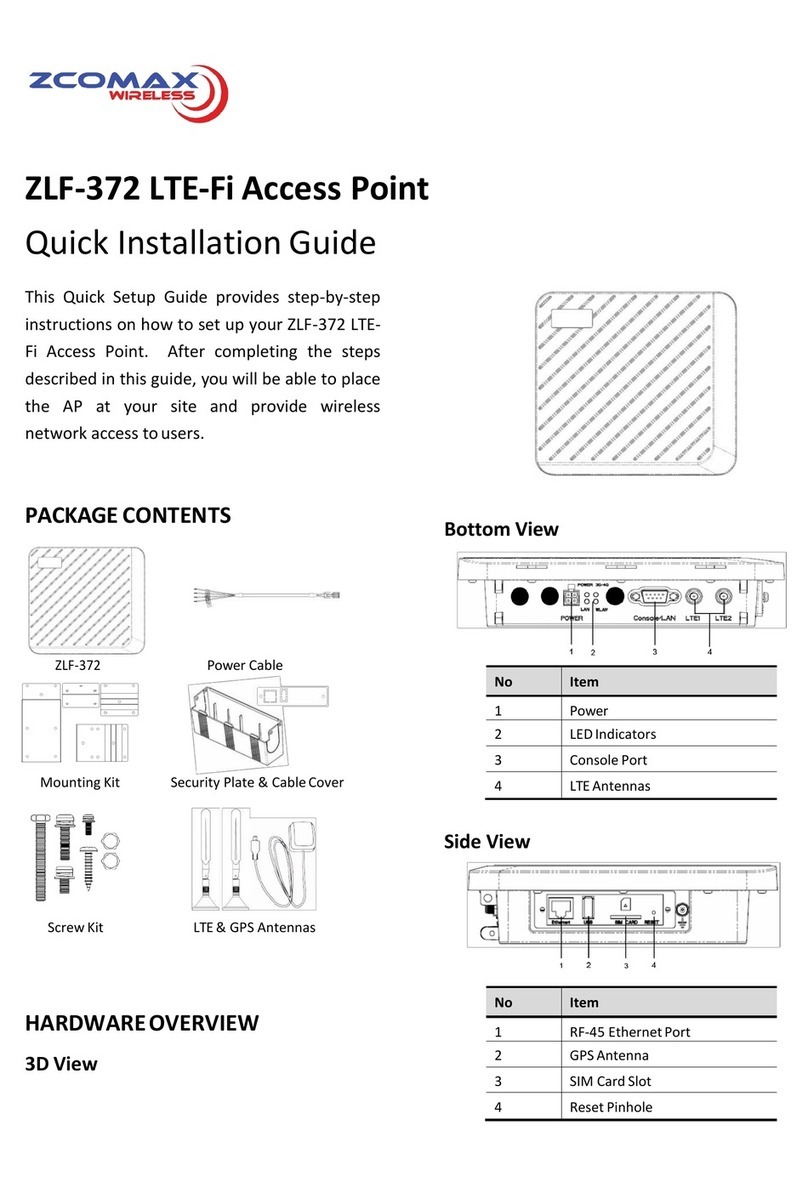
ZComax ZN-1000-ZBS User manual

ZN-1000-ZBS
Smart Access Point
Quick Setup Guide
This Quick Setup Guide provides step-by-
step instructions on how to set up your ZN-
1000-ZBS Smart Access Point. After
completing the steps described in this
Guide, you will be able to place the AP at
your site and provide wireless network
access to users.
PACKAGE CONTENTS
HARDWAREOVERVIEW
Front View
No. Item
1 Metal caps for optional 5GHz antennas
2 LED Indicators
LED Indicators on the Device
LED Indicators on the PoE Injector
No
LED
State
Description
1
Smart
Function
On
(Yellow)
Training
On
(Blue)
Training complete
Off
Disabled
2
AP
Mode
Blinking
(Yellow)
Connected in AC
mode
On
(Yellow)
Connected in AC
mode
On
(Blue)
Connected in FAP
mode
3
System
Blinking
(Red)
System is initializing
On
(Red)
System is unstable
On
(Green)
System is stable
Off
The 2.4G wireless
radio is off
4
PWR
On
(Green)
Power is being
supplied to the
device
via the Ethernet
port
5
PoE
On
(Amber)
Network connection
is established
Blinking
(Amber)
Ongoing data
transmission

SETUP REQUIREMENTS
Before installing your ZN-1000-ZBS accesspoint,
be sure that you have the following:
•
A computer running Windows 7, Vista, orXP
•
A CAT5 UTP cable of required length
•
One of the following power sources:
-IEEE 802.3at-compliant Power over Ethernet
(PoE) source
-Power adapter came with thepackage
STEP 1: POWER ON THE AP
The Smart Access Point comes with a PoE
injector kit for connecting to power over the
Ethernet port. The Smart Access Point
automatically turns on as soon as it is connected
to a power source.
1. Insert one end of an Ethernet cable tothe
P+D/OUT port on the PoE injector.
2. Insert the other end to the LAN/PoE port
on the Smart Access Point.
3. Connect a power cord to the PoE injector.
4. Connect the power plug to a wall socket.
STEP 2: CONNECT THE AP TO YOUR PC
1. Insert one end of an Ethernet cable to the
Data/IN port on the PoE injector as figured
above.
2. Insert the other end to the assigned LAN port on
your PC as figured above.
3. From your computer, go to Start > Settings >
Network Connections or Start > Control Panel>
Network Connections.
4. When the Network Connections window
appears, right-click the icon for Local Area
Connection, and then click select Properties.
5. Select Internet Protocol (TCP/IP) from the
scrolling list, and then click Properties.
6. Select Use the following IP address option (if it
is not already selected), and then make the
following entries:
•
IP address: Any address in the 192.168.1.x
network
• Subnet mask: 255.255.255.0
7. Click OK to save your changes, and exit the
dialog box.
STEP 3: LOG INTO THE AP
1. On your PC, open a Web browser window.
2. In the browser, type https://192.168.1.1 and
press <Enter> to connect to the AP.
3. When a security alert dialog boxappears,
click OK/Yes to proceed.
4. When the login page appears, enter the
following:
•
Username: admin
•
Password: password
5. Click Login.
STEP 4: CONFIGURE THE AP
1. On the Web interface menu, click Advanced
Settings.
2. Select Wireless Mode: FAT AP.
3. Select DHCP Client to obtain an IP address
from the DHCP server automatically, or
select STATIC to enter the values manually.
Click Apply to save changes.
4. Go to RF Configure > Wireless Settings. (For
dual band 5G setting, select Card 2first
then go to RF Configure > WirelessSettings.)
5. Select your location fromCountry/Region.
Click Apply to save the changes.
6. Select a clean channel.
7. Go to RF Configure > SecurityProfile
8. Select a profile (eg. #1) , then click Edit.
9. Type the name of the network in the SSID
field.
10. Enable authentication and encryption as
needed. Click Apply to save the changes.
11. Repeat Steps 8-9 for each Profile #interface
that you want to enable.
12. Click Logout to exit the Webinterface.
Cautions:
1. Use only the power adapter and PoE injector
that came with the wireless AP.
2. Make sure that the PoE injector is properly
grounded
Note:
If the AP is deployed with an AP controller,
follow the section INSTALL THE AP to proceed.

STEP 5: INSTALL THE AP
1.
Disconnect the AP’s power adapter from the
power outlet (or disconnect the PoE cable).
2.
Move the AP to its permanent location
(accessible to both power source and
network connections).
MOUNTING ON A FLOATING CEILING
1. Secure the smart antenna to the
mounting base with the providedscrews.
2. Press the mounting bracket to the T-bar
at a pre-determinedlocation.
3. On the opposite side of the T-bar,
position the T-bar clip.
4. Insert the washers over the retaining
screws and insert through the T-barclip
and into the mountingbracket.
5. Secure the Smart Access Point and
mounting base to the mounting bracket
with the spring washers and screws.
6. Align the Smart Access Point and
mounting base assembly with the
mounting bracket.
7. Insert the adjusting screws throughthe
mounting base and secure.
STEP 6: WATERPROFFING THE CABLE
For outdoor installation, you need to waterproof the
LAN port using the supplied sealingcap.
1. Slide the locking nut over the bare endof
the Ethernet cable.
2. Slightly pry open the gasket and rubber
stopper, and insert the Ethernet cable.
3. Slide the gasket and rubber stopper into
the locking nut.
4. Connect the RJ-45 connector into the
smart antenna LAN port.
5. Flush the gasket, rubber stopper and
locking nut together into the LAN port
opening, then twist the locking nut to seal
the opening.
6. Slide the sealing cap over the bare endof
the Ethernet cable.
7. Tighten the sealing cap.
Note:
Do not tighten the screws completely at this
time to allow for final tilt down adjustments.
Note:
The Smart Access Point is ideal for closed and
semi-outdoor environments. The signal strength
it will receive depends largely on its position, so
make sure that sufficient survey has been made
to determine the best placement for maximum
range, coverage, and network performance
before installing.

INSTALLING THE ANTENNA (OPTIONAL)
You may install optional 5GHz antennas on top
of the Smart Access Point to extend the rangeof
your wireless network.
1. Unscrew the metal caps protecting theantenna
connectors.
2. Connect the 5GHz antennas to the standardN-
type female antenna connectors on theAP..
3. Attach waterproof tapes to the connectors to
protect the antennas from water and dirt.
STEP 7: POWER AND CONNECT
1. Connect the Ethernet cable from the DataIn
port on the PoE injector to your network’sswitch.
2. Connect the PoE injector to an AC power
source.
3. Perform a spot-check to verify if the PWR and
LAN LED are lit to make sure the AP is
operating normally
STEP 8: VERIFY THE CONNECTION
1.
Use any wireless-enabled computer or mobile
device to search for and select the wireless
network you’ve previouslyconfigured.
2.
If you can connect, open a browser and linkto
any public Web site.
If you are using AP Controller to manage the AP,
please refer to the AP Controller user guide to
learn how to configure and manage the AP from
the AP Controller Webinterface.
The latest versions of user manuals areavailable
for download on the ZDC website at:
www.zcom.com.cn
Copyright © 2016 Zcomax Technologies, Inc. All
rights reserved. All other company and product
names mentioned in the documentation are held to
be trademarked (and registered) by the primary
holders.
Cautions:
1. Make sure that you disconnect the Smart
Access Point from the power source before
connecting the optional antennas
2. Do not remove the metal caps if you are not
installing 5GHz antennas
Other ZComax Wireless Access Point manuals
Popular Wireless Access Point manuals by other brands

Cisco
Cisco Aironet 2600 Series Getting started guide

Juniper
Juniper Mist AP32 Deployment guide

Formosa
Formosa AG-3621 manual

NETGEAR
NETGEAR WAG302 - ProSafe Dual Band Wireless Access... Reference manual

Netgate
Netgate Wireless Multi-Client Bridge user manual

Beijer Electronics
Beijer Electronics JetWave 4020 Series user manual