Reliance electric PSC7000 User manual

Instruction Manual 23030-6E
PSC7000 Control Card
for PSC7000 Controller
Instruction Manual
Reliance Electric Limited

The information in this instruction manual is subject to change without notice.
Reliance Electric assumes no responsibility for errors that may appear in this manual.
Reproduction of a part or an entirety of this instruction manual is prohibited without any writ-
ten approval of Reliance Electric Limited in advance.
Throughout this manual, the following attentions are used to alert you to safety consideration.
ATTENTION: Identify information about practices and circumstances that can lead
to personal injury or death, property damage, or economic loss.
Important: Identify information that is critical for successful application and understanding
of the products.
ATTENTION: Only qualied personnel familiar with the construction and operation
of this equipment and hazards involved should install, adjust, operate or service
this equipment. Read and understand this instruction manual and other applicable
manuals in their entirety before processing. Failure to observe this precaution could
result in bodily injury and/or damage to the equipment.
ATTENTION: Inserting and removing the control Card or its connecting cables may
result in unexpected machine operation. Power to machines should be turned off be-
fore inserting or removing the card or its connecting cables. Failure to observe this
precaution may result in bodily injury or damage to the equipment and/or machines.
ATTENTION: The Control Card contains electrostatic discharge-sensitive compo-
nents. Careless handling may result in severe damage on the components. Do not
touch the connections on the back of the Control Card. Failure to observe this pre-
caution may result in damage to, or destruction of, the equipment.
!
!
!
© 2008 Reliance Electric Limited
!

i
Table of Contents
Table of Contents
2 Components Formation ........................................................................... 2-1
2.1 PSC7000 Control Card ............................................................................... 2-1
2.2 Peripheral Devices ..................................................................................... 2-2
3 Description of Mother Chassis................................................................ 3-1
3.1 Status Indicator........................................................................................... 3-2
3.2 System Switch ............................................................................................ 3-2
3.3 Terminal Connector .................................................................................... 3-2
3.4 Up & Down Button Switch .......................................................................... 3-2
3.5 CPU OK LED Indicator ............................................................................... 3-2
3.6 BAT. OK LED Indicator ............................................................................... 3-2
3.7 Access LED Indicator................................................................................. 3-2
3.8 CF Card Insert Inlet .................................................................................... 3-2
4 Specications ........................................................................................... 4-1
4.1 Mother Chassis........................................................................................... 4-1
4.2 DSP Modules (DSPM-1A & DSPM-2A) ....................................................... 4-2
4.3 PG Modules (MCIM-1 & MCIM-2)............................................................... 4-3
4.4 SERCOS Module (SRCS-1) ........................................................................ 4-4
4.5 Terminal Block for PG Module .................................................................... 4-4
4.6 Boundary Dimensions ................................................................................ 4-5
4.6.1 Mother Chassis (include Modules)................................................ 4-5
4.6.2 Terminal Block of PG Module and cable....................................... 4-5
4.7 Installation Dimensions............................................................................... 4-6
5 Mounting and Dismounting of Modules ................................................. 5-1
5.1 Mounting Procedures of Modules............................................................... 5-1
5.2 Dismounting Procedures of Modules ......................................................... 5-3
6 Change of Battery..................................................................................... 6-1
6.1 Battery replacement for DSPM-1A ............................................................. 6-1
6.2 Battery Replacement for DSPM-2A ............................................................ 6-3
7 CompactFlash (CF) Memory Card........................................................... 7-1
7.1 Outline of CF Memory Card........................................................................ 7-1
7.2 External Appearance of CF Memory Card ................................................. 7-1
7.3 Inserting Method of CF Memory Card........................................................ 7-2
7.4 Removing Method of CF Memory Card...................................................... 7-2
7.5 Saving Method into CF Memory Card ........................................................ 7-2
7.6 Downloading Method from CF Memory Card............................................. 7-3
8 Connection with PSC Terminal ................................................................ 8-1
8.1 Connecting Method of USB Cable ............................................................. 8-1
8.2 Connecting Method for DCS Programmer Cable....................................... 8-2
Contents ...................................................................................................................i
Preface ...................................................................................................................v
1 Outline ....................................................................................................... 1-1

ii PSC7000 Control Card Unit
9 Connect PG Module and External Wiring ............................................... 9-1
9.1 Connect PG Signal Input............................................................................ 9-2
9.2 Connect Mark & Origin Point Signal Inputs ................................................ 9-3
9.3 Connect Analog Signal Output................................................................... 9-3
9.4 Other Terminals on Terminal Block of PG Module ...................................... 9-3
10 Programming .......................................................................................... 10-1
10.1 System Variables ...................................................................................... 10-1
10.1.1 Counter Variable (CHn_COUNTER!) ........................................... 10-1
10.1.2 Latch Variables............................................................................ 10-2
10.1.3 Pulse Multiplying Rate Variable (CHn_MULT!) ............................ 10-3
10.1.4 Input Logic Variables .................................................................. 10-4
10.1.5 Input Selection Variables............................................................. 10-5
10.1.6 Analog Output Variable (CHn_ANALOG_OUT!) ....................... 10-13
10.1.7 Latch Signal Status Input Variables (CHnZZZ@,
CHnMRK@, & CHnORG@)........................................................ 10-13
10.1.8 System Switch Variable (AUTORUN@) ..................................... 10-13
10.1.9 Battery Status Variable (BATTERY@)......................................... 10-13
10.1.10 Battery Status Warning Variable (BTYWAR@) ........................... 10-13
10.1.11 SynchroCard Synchronizing Status Variable............................. 10-13
10.1.12 SynchroCard Interval Variable................................................... 10-13
10.2 Using Method of System Variables......................................................... 10-14
10.3 List of System Variables.......................................................................... 10-14
10.4 Wire-Breaking Detection Function of PG Module................................... 10-19
11 Error Codes ............................................................................................ 11-1
12 Troubleshooting...................................................................................... 12-1
12.1 CPU OK Lamp is Off................................................................................. 12-1
12.2 BAT. OK Lamp is Off................................................................................. 12-1
13 Appendix ................................................................................................. 13-1
13.1 Devices for PSC7000 Series Controllers .................................................. 13-1
13.2 Use Restrictions of PSC Option Cards ..................................................... 13-2

iii
Table of Contents
List of Figures
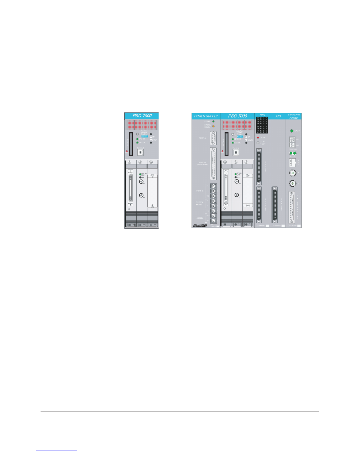
Figure 1-1 PSC7000 Control Card .......................................................................1.1
Figure 1-2 PSC7000 Controller (System)............................................................ 1-1
Figure 2-1 Components Formation for PSC7000 Control Card .......................... 2-1
Figure 2-2 Peripheral Devices for PSC7000 Controller....................................... 2-2
Figure 3-1 Names of Indicators, Buttons & Inlet................................................. 3-1
Figure 4-1 Boundary Dimensions of Mother Chassis ......................................... 4-5
Figure 4-2 Boundary Dimensions for Terminal Block of
PG Module and Cable ....................................................................... 4-5
Figure 4-3 Installation Dimensions...................................................................... 4-6
Figure 7-1 External Appearance of CF Memory Card........................................ 7-1
Figure 7-2 Inserting Method of CF memory Card............................................... 7-2
Figure 7-3 Downloading Method from CF Memory Card to
PSC7000 Controller ........................................................................... 7-3
Figure 8-1 Connecting Method for USB Cable................................................... 8-1
Figure 8-2 Connecting Method for DCS Programmer Cable.............................. 8-2
Figure 9-1 Connecting method for Cable of PG Module .................................... 9-1
Figure 9-2 Interface Circuit for PG Signal Input of MCIM-1................................ 9-2
Figure 9-3 Interface Circuit for PG Signal Input of MCIM-2................................ 9-2
Figure 9-4 Interface Circuit for Mark Signal & Origin Point Inputs...................... 9-3
Figure 9-5 Interface Circuit for Analog Signal Output ........................................ 9-3
Figure 10-1 Example for Transition of Counter Variable
(4 Times Multiplying) ..................................................................... 10-1
Figure 10-2 Example for Transition of Z Pulse Latch Variable .......................... 10-2
Figure 10-3 Counting Edges at One-Time Mode (MCIM-2 only)...................... 10-3
Figure 10-4 Counting Edges at Two-Time Mode .............................................. 10-4
Figure 10-5 Counting Edges at Four-Time Mode ............................................. 10-4
Figure 10-6 Example for Transition of Input Logic Variable .............................. 10-4
Figure 10-7 Variable 0 (Up Edge of Origin Signal at Reverse Rotation)......... 10-10
Figure 10-8 Variable 1 (Up Edge of Origin Signal at Forward Rotation.......... 10-10
Figure 10-9 Variable 2 (Up Edge of Origin Signal at Both of Forward
and Reverse Rotation)................................................................ 10-11
Figure 10-10 Variable 3 (Up Edge of Origin Signal
When Z Pulse is True at Reverse Rotation)............................... 10-11
Figure 10-11 Variable 4 (Up Edge of Origin Signal
When Z Pulse is True at Forwartd Rotation) ............................. 10-11
Figure 10-12 Variable 5 (Up Edge of Origin Signal When Z Pulse is
True at Both of Forward and Reverse Rotation)........................ 10-11
Figure 10-13 Variable 6 (Down Edge of Z Pulse When Origin Signal is
True at Reverse Rotation) ......................................................... 10-12
Figure 10-14 Variable 7 (Up Edge of Z Pulse When Origin Signal is
True at Forward Rotation) ......................................................... 10-12
Figure 10-15 Variable 8 (Equal to OR of Variables 6 and 7)........................... 10-12
Figure 10-16 Counter Points of PG Signal ...................................................... 10-19
Figure 13-1 Devices for PSC Series Controllers ............................................... 13-1

iv PSC7000 Control Card Unit
List of Tables
Table 2-1 List of Components for PSC7000 Control CardFigure .........................2.1
Table 4-1 Specications for Mother Chassis ...................................................... 4-1
Table 4-2 Specications for DSP Modules.......................................................... 4-2
Table 4-3 Specications for PG Modules............................................................ 4-3
Table 4-4 Specications for SERCOS Module.................................................... 4-4
Table 9-1 List for PG Module Signals.................................................................. 9-1
Table 9-2 List of Other Terminals of PG Module ................................................. 9-4
Table 10-1 Selected Items for Standard Latch Input Selection Variable
(Channels 1 to 3) ............................................................................ 10-6
Table 10-2 Selected Items for Standard Latch Input Selection Variable
(Channels 4 and 5)......................................................................... 10-7
Table 10-3 Selected Items for Standard Latch Input Selection Variable
(Channels 6 to 8) ............................................................................ 10-8
Table 10-4 Selected Items for Standard Latch Input Selection Variable
(Channels 9 to 10) .......................................................................... 10-9
Table 10-5 Selected Items for Origin Point Latch Input Selection Variable .... 10-10
Table 10-6 List of Common System Variables ................................................ 10-14
Table 13-1 List for PSC Series Various Option Cards ....................................... 13-2

Preface
Preface
This PSC7000 control card described in this instruction manual is manufactured or dis-
tributed by Reliance Electric Limited.
This instruction manual describes all functions necessary to attain with this product re-
garding, its outline, mounting and dismounting procedures, operating methods for the
PSC7000 control card. Please read and understand all functions of the product prior to
the use of the product. Further, keep this instruction manual within easy reach of per-
sonnel necessary for the manual.
ATTENTION: Only qualied electric personnel familiar with the construc-
tion and operation of this equipment and the hazards involved shall install,
adjust, operate or service the equipment. Read and understand this
instruction manual and other applicable manuals in their entirety before
processing. Failure to observe this precaution could result in bodily injury
or damage on this equipment.
This revised instruction manual contains the update contents as of April 2008. The ver-
sion of the operating system (OS) of the PSC7000 Controller is 0.67. The version of the
PSC Terminal software is 0.22.
Upon arrival of the equipment, the user is responsible to thoroughly inspect the equip-
ment before accepting the shipment. If any items are missing or are found obviously
damaged, notify our ofce or our agent of the fact.
Notes on Handling
When the PSC7000 Control Card is installed, adjusted, operated, or serviced, the fol-
lowing precaution must be paid in advance and/or during the operation because the
product is made of ne electronic components.
1) The operating temperature range is 0 to 55 degree C (32 to 131 degree F).
Do not operate or store the card at a place under direct sunshine, close to a
heater, or with high humidity.
2) Any heavy shocks or vibrations shall be avoided from the product.
3) Prevent metallic foreign materials such as paper clips from entering into the
product.
4) Upon installing the equipment, only electric personnel familiar with construction
and operation of the product and applicable codes and standards shall perform
installing work.
5) Turn off the power source to the PSC7000 controller before installing or removing
the product. Installing or removing the card while the PSC7000 system is
powered on might cause trouble or damage to the product.
6) The product uses electrostatic-discharge sensitive components. Exercise caution
to electrostatic-discharge which might cause destruction of such components.
7) Do not touch connectors and/or surface of the circuit board in the product to
prevent possible failure of their electrically connecting conditions.
8) Do not perform what the items do not described in this manual is recommended
9) When inserting or pulling out the connectors, recommend to hand the plug instead
of pulling their cables in order to prevent future contact trouble of the connectors.
!
v

Preface
vi
10) Please observe the mounting, adjusting, testing, or dismounting procedures
described in this manual. Otherwise, unexpected damage or trouble of the product
might be caused.
11) When disconnecting cables, please pull out their connectors instead of the cables
in order to avoid damage on cable connection.

1-1
Outline
Chapter 1
Outline
The PSC7000 Control card is a control card packing major necessary functions into
one card in order to realize servo controlling. The PSC7000 controller has realized
the servo control functions so that the users can arbitrarily program the control card,
and also has input and output circuits necessary for servo control such as feedback
input and analog output.
Three slots mountable for various modules are provided at the lower part of the
PSC7000 control card. At the present time, the following modules such as DSP mod-
ule, PG module or the like can be mounted into the slots in the case of need.
• DSP Module:
This module includes the built-in DSP processor in order to execute servo control
programs. At least one DSP module is necessary in this control card.
• PG Module:
This module provides 5 channels for incremental pulse encoder input (hereafter
called as PG input), and 5 channels for analog output.
• SERCOS Module:
This module is the SERCOS master module in order to realize SERCOS communi-
cation with the drive system.
The PG module mountable on the PSC7000 control card has independent 5 chan-
nels each for input and output circuits. Therefore, one PG module can control
independent ve axes at the same time. The PSC7000 control card can provide the
maximum two PG modules, which can control ten axes. Each channel has the follow-
ing input and output.
• PG input: Two phase pulse with 90 degree phase-difference, and Z pulse.
• Respective mark and origin latch input.
• +/-8V or +/-10V analog output.
Figure 1-1 PSC7000 Control Card Figure 1-2 PSC7000 Controller (System)

1-2 PSC7000 Control Card
Application programs are necessary for servo control, and programming and down-
loading of the application programs are carried out in the PSC7000 controller by
using the PSC terminal software (type: MH-5009, component No: 881030) installed
in the PC.
Flash memories memorizing the downloaded programs are built in the DSP module
of the PSC7000 control card. Therefore, these downloaded programs are not disap-
peared in the control card even though its power source is turned off or the PSC7000
control card is dismounted from the PSC backplane. The battery for the DSP module
is used to save nonvolatile variables (NVMEMDEF and NVLOCAL variables). The
values changeable at real time can be also saved.
The application programs can be also saved in the optional compactash (CF)
memory card as an optional card. The application programs saved in the CF memo-
ry card can be again downloaded to the PSC7000 controller by means of operation
of the system switch. Therefore, when the current control card is exchanged with the
new PSC7000 control card, the same application programs can be downloaded to
the PSC7000 controller without aids of the PSC terminal.
The PSC7000 control card is the enhanced version of the PSC5000 control card.
The boundary dimensions are compatible with the control cards of the PSC series
products such as the PSC3000, PSC4000, and PSC5000. The programmable servo
controller can be realized by using together with the power supply card, the back-
plane, and various option cards as well as the PSC series controllers.
Major Features of PSC7000 Control Card:
High Speed Processing Capability:
Realize high speed calculation of 150MFLOPS by means of DSP
Increase for Number of Controlling Axes:
Realize the maximum 10 axes for motor control per one control card when two sets
of the PG modules are mounted.
Improved Freedom for Signal Feedback:
Realize the control system using the SERCOS module by replacing modules as
well as conventional PG signal feedback.
The following functions are also provided to realize satisfactory user interfaces:
USB2.0:
Realize high speed communication with the PC, and shorten required download
ing and uploading time of the application programs during programming or main
tenance service.
CF Memory Card:
Adopt the compact CF memory card with large volume and high speed accessing
as a record medium for application programs.
Dot Matrix LED Display:
Display the status of the PSC7000 control card, and also display error codes when
any error happens.

2-1Components Formation
Components Formation
2.1 PSC7000 Control Card
The PSC7000 control card is organized of the following components.
Chapter 2
The various modules shown above are mounted on the slots (Conform to Compact-
PCI Standard, see the note 1) located at the lower part of the PSC7000 control card
(conform to the compact PCI standard, see the note 1) if necessary. The PSC7000
controller applicable to various applications can be organized. The DSP module
should be mounted at the slot 3 located at the far right.
Table 2-1 List of Components for PSC7000 Control Card
Name
Mother Chassis
DSP Module
PG Module
SERCOS
Module
Blank Panel
Type (Drawing No)
Mother chassis
(WR-D4008)
DSPM-1A (S-D4031)
DSPM-2A (S-D4041) *2
MCIM-1 (WR-D4009)
MCIM-2 (S-D4043) *3
SRCS-1 (S-D4039)
Blank panel MB-D4017
Part No
843001
843705
843710
843708
843712
843709
133003
Description
Necessary modules such as DSP
module are mounted on lower slots.
Mounted on the slot 3 (far right side) at
the bottom of the mother chassis.
Necessary modules are mounted on
the slot 1 or 2 at the bottom of the
mother chassis.
Necessary module is mounted on the
slot 1 or 2 at the bottom of the mother
chassis.
It is mounted on the open slot at the
bottom of the mother chassis.
Note *1: PICMG and CompactPCI are registered trade marks of PCI Industrial Computer Manufacturers Group.
*2: DSPM-2A is the grade-up version of the DSPM-1A.
*3: MCIM-2 is the grade-up version of the MCIM-1.
Figure 2-1 Components Formation for PSC7000 Control Card
Mother Chassis
SERCOS Module PG Module DSP Module Blank Panel

2-2 PSC7000 Control Card
2.2 Peripheral Devices
The following peripheral devices are provided for the PSC7000 controller.
NAME
Terminal Block for PG Module
Cable for PG Module
Compact Flash Memory
Card, 256MB
Compact Flash Memory
Card, 512MB
PSC Terminal
(CD-ROM)
USB Cable
DCS Programmer Cable
Battery for DSPM-1A Module
(for replacement)
Battery for DSPM-2A Module
(for replacement)
TYPE
PS7XW-10080
MB-D5021
MB-D4014
MB-D4015
MH-D5009
B Type Cable
certified by USB-IF
M-82170
BR-AGC2P
CR2032
(FDK or Maxel)
Part No
365705
174015
882001
882002
881030
-
884015
370861
-
Description
This terminal block relays external
wires connected with PG module,
and are used in the control cabinet.
Connect between PG module and
the terminal block.
Memorize and store data such as
user application programs.
Memorize and store data such as
user application programs.
This is the software tool used for pro-
grams and maintenance, which oper-
ates on the PC.
Connect between the PC and
PSC7000 controller.
Connect between the PC and
PSC7000 controller.
Backup memory of DSPM-1A
module.
Backup memory of DSPM-2A
module.
Figure 2-2 Peripheral Devices for PSC7000 Controller
PSC 256 PSC 512
Terminal Block for PG Module
PSC Terminal
(CD-ROM)
Cable for PG Module
USB Cable
CompactFlash Memory Card
(256MB & 512MB)
Battery for DSPM-2A Module
(For Replacement)
Battery for DSPM-1A Module
(For Replacement)

3-1
Description of Mother Chassis
The mother chassis of the PSC7000 control card is used by mounting it into the slot
0 of the base unit for the PSC7000 controller. Various modules applicable to various
applications can be mounted on the slots (slot 1, slot 2, and slot 3 from the left side)
at the lower part of the mother chassis. The DSP module must be connected with the
slot 3 at the far right side on the lower part of the mother chassis. The status indica-
tor (dot-matrix LED indicator), system switch, Terminal connector, UP button switch,
DOWN button switch, CPU-OK LED indicator, and Access LED indicator, and CF
memory card insertion inlet are mounted on the faceplate of the mother chassis.
Chapter 3
Access LED Indicator
CF Card Insert Inlet
BAT. OK Led Indicator
CPU OK LED Indicator
Status Indicator
(Dot Matrix LED Indicator)
System Switch
UP & DOWN Button
Switches
Terminal Connector
Figure 3-1 Names of Indicators, Buttons & Inlet

3-2 PSC7000 Control Card
3.1 Status Indicator
The status indicator displays characters and gures which show current status of
them when the PSC7000 control card or the system detects any error.
When performing special operation such as downloading of user data from the CF
memory card, the current status of downloading is displayed.
Please refer to the section 7 "Functions and Operation of CF Memory Card" for more
information. When the power source is normally turned on, the display will start from
"Init...", "vX.XX", "PSC7" in order. The "vX.XX" means the version of the OS used for the
PSC7000 controller.
3.2 System Switch
The system switch sets up the AUTORUN of the tasks at the time of starting of the
PSC7000 controller. The tasks will automatically run if this system switch is set at the
neutral position. When pushing down the system button more than three seconds,
the PSC7000 controller will restart, and is initialized. When the CF memory card is
inserted into the mother chassis, user tasks can be downloaded from the CF memo-
ry card, and they can are executed when letting the pushed button go loose.
Please refer to the section 7 "Functions and Operation of CF memory Card" for more
information.
3.3 Terminal Connector
The terminal connector is a connector to connect the PSC terminal by using the USB
cable. The PSC terminal and USB cable are separately prepared for your use in Reli-
ance Electric Limited. Refer to the section 8 "Connection with PSC Terminal" for more
information.
3.4 Up & Down Button Switch
The UP and DOWN button switch is used to display the history of errors on the status
indicator of the PSC7000 controller.
3.5 CPU OK LED Indicator
The CPU-OK LED indicator lights on when the DSP module of the PSC7000 control
card operates properly. When lighting off this LED indicator, refer to the section 11
"Troubleshooting" in this manual for more information.
3.6 BAT. OK LED Indicator
The BAT.OK LED indicator lights on when voltage of the battery in the DSP module
is designated voltage or over. If the indicator is turned off, refer to the section 11
"Troubleshooting" for more information.
3.7 Access LED Indicator
The Access LED indicator lights on when the PSC7000 controller accesses to the CF
memory card.
3.8 CF Card Insert Inlet
The CF card insert inlet is provided to insert the CF memory card. The front surface
of the card is turned to the LED side.

4-1
Specications
Specications
4.1 MotherChassis
The mother chassis is the main body of the PSC7000 control card. The mother chas-
sis is provided with three compactPCI type slots for mounting various modules, and
the indicators and system switches can display the operational status of these mod-
ules.
Table4-1SpecicationsforMotherChassis
Compact PCI Slot
Auxiliary Memory
Provide 3 slots. PICMG2.1, rev3.0
Signal Voltage VIO: 3.3V, 32Bits, 33MHz
CompactFlash memory card
(conformity to PC Card ATA)
Display current status (Error codes)
Turn on when watchdog timer is normal.
Turn on when battery voltage is 2.7V or more.
Turn on while compactFlash memory card is ac-
cessed.
Switchable AutoRun Enable & Disable modes, and
Reset operation
USB ports (for connection with PSC terminal)
Supply 5V power from power card via backplane
5V, 4A: DSPM-1A(x1), MCIM-1(x2), 20x7 dot-matrix
are all turned ON, 10V output for all channels of ana-
log output, maximum current consumption of com-
pactFlash card slot
Storage: -20 to 85 degree C,
Operation: 0 to 55 degree C
W65 x H220 x D222 mm (No modules)
W65 x H220 x D250 mm (when mounting modules)
1718 grams (excluding mounted modules)
Display
Functions
Dot-Matrix 20x7
CPU OK (Green)
Battery OK (Green)
CF Access (Red)
System Switch
External Connection
Power Supply
Capacity for Power Supply
Storage & Operating Temperature
Boundary Dimensions
Weight
Chapter 4
※ Regarding the screw position when installing the PSC rack to the board, please
refer to the 4.7 "Installation Dimensions".

4-2 PSC7000 Control Card
4.2 DSPModule(DSPM-1A&DSPM-2A)
The DSP modules have the built-in high speed processors, and are the modules to
execute servo controlling programs programmed by users. This DSP modules are
inserted at the far right side of the slots in the PSC7000 control card.
Table4-2SpecicationsforDSPModules
Processing Type
DSP Clock
User Memory
Main Memory
Back up Memory
Flash Memory
Batteries for DSP Modules
Loading for User Tasks
Programming Language
Scanning Time
Processing
Speed
BASIC Tasks
PC Ladder Tasks
Control Block Tasks
Consumed Current
Temperature for operation & storage
Boundary dimensions
Weight
Specication of ComactPCI
Multitask & real time processing.
75MHz
2M Byte
1M Byte
8M Byte
DSPM-1A Module:
BR-AGC2P (Matsushita 3.0V 2200mAh)
Memory Support Time: 13.6 years (standard)
Minimum 6.8 years
Recommended Exchange Interval: 5 years
DSPM-2A Modulle:
Coin-type Manganese Dioxide Lithium Battery
CR2032 (Made in FDK or Maxecel, 3.0V,
210mAh)
Memory Support Time: 8 years (standard)
Recommended Exchange Interval:5 years
Built-in ash memory
PSC BASIC language, Control block
language, and PC ladder language
Applicable one of 50 or 62.5 microseconds as
minimum scanning time.
Addition of real number (32 bits): 0.67 microsec-
onds.
Contact : 0.013 microseconds,
Coil: 0.013 microseconds
Addition of real number (32 bits): 0.013-0.08
microseconds
700 mA (3.3V)
Operation: 0 to 55 degree C,
Storage: -20 to 85 degree C
W20 X H130 X D213 mm
193 grams for DSPM-1A
170 grams for DSPM-2A
Signal Voltage VIO: Applicable one of 5V/3.3V
Note: As for the memory support time of the battery, the standard time is based on the conditions of sup-
port current standard value 17.2 uA at ambient temperature 20 degree C.
AS for the minimum memory support time is based on the conditions of support current maximum
value 28.4 uA at ambient temperature -30 degree C.

4-3
Specications
Connector
Storage & Operating Temp.
Boundary Dimensions
Weight
Specication of CompactPCI
5 channels (Signal COM common)
Resolution: +/- 13bits
Gain Error: +/- 55 LSB, Offset Error: +/- 11 LSB,
Low Pass Filter: 1.6 KHz
5 channel each for A, B, & Z phases, totally 15 inputs
5V differential input, RS-422 output type (Equivalent to
Output Drive Am26LS31).
12V emitter follower, 12V totem pole, or 12V open cor-
rector are applicable when using the terminal block of PG
module,
The above are isolated by photo couplers.
For 5V differential input terminal: 2.3V or above.
For 12V input terminal: 5V or above.
MCIM-1, 5V system:
2.5V, 16mA (standard), Impedance=150 ohms
3.0V, 32mA (standard), Impedance=100 ohms
MCIM-1, 12V system:
10V, 9mA (standard), Impedance=1.1K ohms
MCIM-2, 5V system:
2.5V, 8mA (standard), Impedance=300 ohms
3.0V, 13mA (standard), Impedance=230 ohms
MCIM-2, 12V system:
10V, 9mA (standard), Impedance=1.1K ohms
300 KHz per single phase, 1.2 MPPS ( four times)
5 channels each (MARK, ORG), totally 10 inputs
12-24V input
MCMI-1:
ON Voltage= 5.5V+/-1V, OFF Voltage= 4.6V+/-1V
MCIM-2:
ON Voltage=6.5V+/-1V, OFF Voltage=5.5V+/-1V
Time delay: 0.1 milliseconds
80 pins, Screw lock type (Type: Hirose, DX10BM-80S)
Storage:-20 to 85 degree C, Operation: 0 to 55 degree C
W20 X H130 X D213 mm
272 grams for MCIM-1
164 grams for MCIM-2
MCIM-1: Applicable both 5/3.3V for signal voltage VIO
MCIM-2: Applicable 3.3V only for signal voltage VIO
No. of Channel
Output Type
Output Property
No of Channels
Input Type
Threshold
Line Current
Max. Frequency
No of Channels
Input Type
Threshold
Input Property
Analog Refer-
ence Signal
Output
PG Signal
Input
Inputs for
Mark Detect-
ing Signals &
Origin Point
Detecting
Signals
4.3 PGModules(MCIM-1&MCIM-2)
The PG modules are modules with feedback signal input and analog signal output.
The modules are inserted into the slot of the PSC7000 control card if necessary.
Table4-3SpecicationsforPGModules

4-4 PSC7000 Control Card
4.5 TerminalBlockforPGModule
Number of Terminals
Screw size for Terminals
Rated Voltage
Rated Conducting Current
Recommended Wire
Insulated Resistance
Regular Voltage-Resistance
Specied Thunder Impulse
Tightening Torque of Terminal Screw
Storage & Operating Temperature
Relative Humidity
100 terminals (two sets of terminal blocks with
each 50 terminals)
M3 screw
DC 24V
0.5A
1.25 mm2
Beyond 1000 M ohms (between grounds at
DC500V insulation tester)
AC1000V at one minute (between grounds)
1.2 to 50 microseconds at 1500V (between
grounds, Type of transient over-voltage: II class)
0.5 to 0.75 N-m (when using pressure terminal)
Storage: -30 to 85 degree C,
Operation: -20 to 55 degree C
45 to 85 % R.H.
4.4 SERCOSModule(SRCS-1)
The SERCOS module is a module to be used for SERCOS communication with the
drive system. This module is mounted on the PSC7000 control card if necessary.
This module emits invisible radiant light. Therefore, do not look at the sectioned fac-
es of the connectors and optical cables, or any connectors of optical transmission
products to the connection destination, or direrectly red light. It may cause damage
on your eyes.
Table4-4SpecicationsforSERCOSModule
Optical ring
4 Mbps
62.5 microseconds to 10 milliseconds
Max. 16
12 registers per node at both of upward and downward
Max. 20 meters
RFA3051TV-xxx (Made of Mitsubishi Rayon)
(xxx:length of cable, 10 cm Min., Ex. 050 = 500 cm= 5 m)
Storage: -20 to 85 degree C, Operation: 0 to 55 degree C
W20 X H130 X D213 mm
150 grams
Signal Voltage VIO: 5V/3.3V
Transmission Type
Communication Speed
Transmitting Interval
Number of Nodes
Interval Data
Distance between Nodes
Applicable Optical Cable
Storage & Operating Temp.
Boundary Dimensions
Weight
Specication of CompactPCI
Notes: Regarding signal voltage VIO 3.3V for the CompactPCI, the MCIM-2 can not be used together
with the mother chassis of the version REV 1.0 or older, accordingly.
The MCIM-2 can not be mounted by means of the protect key built-in the connector.
Therefore, do not force to mount the MCIM-2. Otherwise, it may cause damage of equipment
or troubles caused by erroneous control operations.

4-5
Specications
4.6 BoundaryDimensions
4.6.1 MotherChassis(includeModules)
Figure4-1BoundaryDimensionsofMotherChassis
Figure4-2BoundaryDimensionsforTerminalBlockofPGModuleandCable
4.6.2 TerminalBlockofPGModuleandCable

4-6 PSC7000 Control Card
Figure4-3InstallationDimensions
4.7 InstallationDimensions
The Figure 4-3 shows the installation dimensions for 4 slots (FSPB-1).
( ): Dimensions for 5 slots (FSBP-2)
[ ]: Dimensions for 6 slots (SSBP-2)
Other manuals for PSC7000
1
Table of contents
Other Reliance electric Control Unit manuals

Reliance electric
Reliance electric GV3000 User manual

Reliance electric
Reliance electric 57C430B User manual

Reliance electric
Reliance electric AutoMax R-Net User manual

Reliance electric
Reliance electric AutoMax DPS User manual

Reliance electric
Reliance electric AutoMax 57C430A User manual

Reliance electric
Reliance electric GV3000 User manual

Reliance electric
Reliance electric MD65 User manual