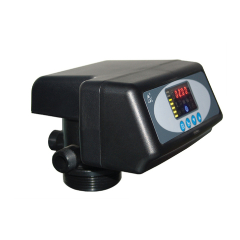
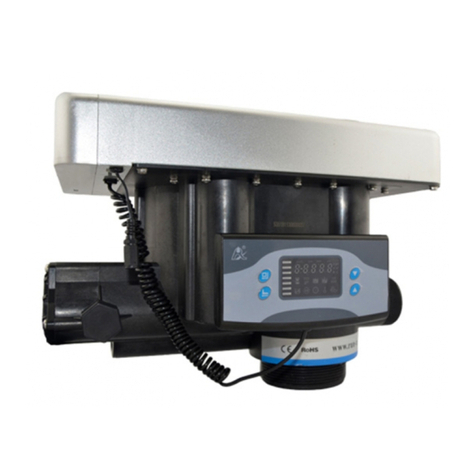
Runxin F139 User manual

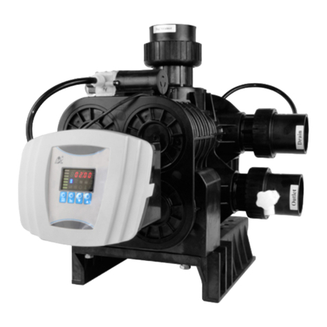
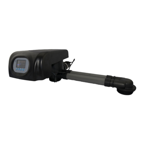
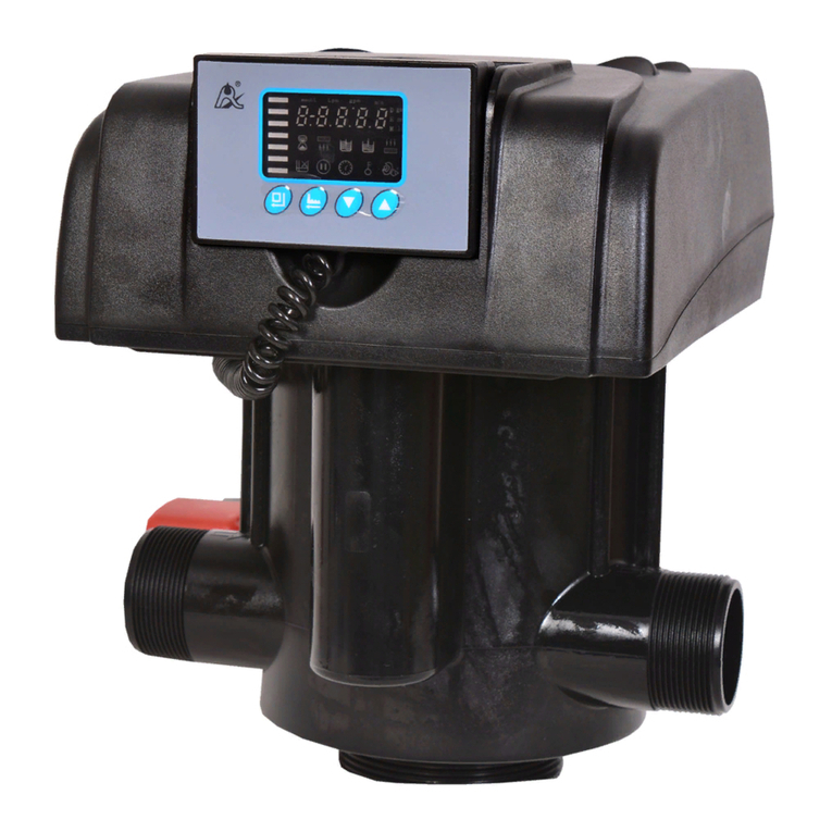
53524 (F139)
51524 (F139S)
Multi-functional Flow Control Valve for
Swimming Pool System
Instruction Manual
Please read this manual in details
before using this valve and keep it properly
in order to consult in the future
0WRX.466.756
WENZHOU RUNXIN MANUFACTURING MACHINE CO.,LTD
ADD: NO.169, RUNXIN ROAD, SHANFU TOWN, WENZHOU, ZHEJIANG, CHINA.
TEL.:0086-577-88630038, 88576512, 85956057 FAX:0086-577-88633258
E-MAIL: [email protected] http://www.run-xin.com
Rev.A. 1082

Before the valve put into use, please fill in the below content so as to help us to refer in
the future.
Filter System Configuration
Tank Size: Dia. mm, Height mm;
Refilled Filter Material Kg;
Granularity of Filter Material mm;
Control Valve Model ; Number ;
Pressure of Inlet Water MPa;
Turbidity of Inlet Water FTU.
Parameter Set
Parameter Unit Factory Default Actual Value
Time of Day
Service Days (By Day)
Rinsing Time
Backwash Time
Rinse Time
h:m
D
/
min
min
Current Value
10
02:00
10
10
MODEL:53524-F139/51524-F139S
-1-

3
4
4
4
4
5
6
8
8
11
13
13
15
16
17
18
20
23
Notice
1.Product Overview
1.1.Main Application & Applicability
1.2.Product Characteristics
1.3.Service Condition
1.4.Product Structure and Technical Parameters
1.5.Installation
2.Basic Setting & Usage
2.1.The Function of PC Board
2.2.Basic Setting & Usage
3.Applications
3.1.Flow Chart
3.2.The Function and Connection of PC Board
3.3.System Configuration and Flow Rate Curve
3.4.Trial Running
3.5.Trouble-Shooting
3.6.Assembly & Parts
4.Warranty Card
MODEL:53524-F139/51524-F139S
Catalogue Notice
●To ensure normal operation of the product, please consult with professional installation
or repairing personnel before use it.
●If there are any of pipeline engineering and electric works, there must be finished by
professional at the time of installation.
●Do not use the control valve with the water that is unsafe or unknown quality.
●Depending on the changing of working environment and water requirement, each par-
ameter of filtration should be adjusted accordingly.
●Test water periodically to verify that system is performing satisfactorily.
●Do not put the valve near the hot resource, high humidity, corrosive, intense magnetic
field or intense librations environment. And do not leave it outside.
●Forbidden to use the drain pipe or other connectors as support to carry the system.
●Please use this product under the water temperature between 5~50℃, water pressure
<0.25MPa. Failure to use this product under such conditions voids the warranty.
●If the water pressure exceeds 0.25MPa, a pressure reducing valve must be installed in
front of the water inlet.
●It is suggested to install PPR pipe, corrugated pipe or UPVC pipe, instead of TTLSG
pipe.
●Do not let children touch or play, because careless operation may cause the procedure
changed.
●When the attached cables or transformer of this product are broken, they must be changed
to the one that is from our factory.
-2- -3-
MODEL:53524-F139/51524-F139S

1.Product Overview
1.1. Main Application & Applicability
Used for swimming pool filtration equipment.
1.2. Product Characteristics
●Simple structure and reliable sealing
It adopts hermetic head faces with high degree pottery and corrosion resistance for
opening and closing. It combines with Filter, Backwash, Rinse, Waste, Recirculation and
Closed.
●Manual function
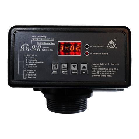
Under unlock status, realize rinsing immediately by pressing “ ” at any time.
●Long outage indicator
If outage overrides 3 days, the time of day indicator “12:12” will flash to remind people
to reset new time of day. The other parameters do not need to be reset. The process will
continue to work after powering on.
●Buttons lock
No operations to buttons on the controller within 1 minute, button lock indicator lights
on which represents buttons are locked. Before operation, press and hold the “ ” and
“ ” buttons for 5 seconds to unlock. This function can avoid incorrect operation.
●Remote handling connector
This connector can receive external signal and control the valve remotely. (The wiring
refers to Figure 3-2)
●All parameters can be modified
According to the water quality and usage, the parameters in the process can be adjusted.
●The service days can be set
Under the situation of service reaching the setting days and the pressure not yet, it could
enter into rinsing process when current time is the same as rinsing time.
1.3. Service Condition
This control valve should be used under the below condition.
Item Requirement
Working
conditions
Working
environment
Inlet water quality
Water pressure
Water temperature
Environment temperature
Relative humidity
Electrical facility
Water turbidity
●When the water turbidity exceeds the conditions, the impurity in the inlet water should
be coagulated and precipitated firstly.
1.4. Product Structure and Technical Parameters
A.Dimension (The appearance is just for reference. It is subjected to the real product)
28
47 28
150170
225.2 225.2
84 (315)
51
Φ149
51
F139 Structure chart
Pressure
Gauge
Drain
Inlet
Outlet
Top Strainer
Riser Pipe
B. Technical parameter
The suitable transformer output of control valve: DC24V, 1.5A.
F139
F139S
24
-4- -5-
MODEL:53524-F139/51524-F139S MODEL:53524-F139/51524-F139S
<0.25MPa
5℃~50℃
5℃~50℃
≤95%(25℃)
AC100~240V/50~60Hz
<20FTU
Model
Connection Size Backwash
Flow Rate
3
m /h
@0.1MPa
Remark
Glue Connection
for Inlet/
Outlet/Drain
Base Riser Pipe
2"D-GB
(OD:63.3 mm
UPVC pipe)
or 2.375"OD
(OD:60.3mm
UPVC pipe)
Clamp (Suitable
for tank internal
diameter with
150mm)
1.5"D-GB
(OD:50mm)
or 1.9″OD
(OD:48.3mm)
Pressure or
time to initiate
backwash
Manual

② As the Figure 1-3 shows, installation of Outlet/Inlet/Drain Pipeline.
a.A water pump should be installed at the inlet, and filter net should be installed in front
of the water pump.
b.The back end of the outlet pipeline can be connected to “other system”, such as heating
systems, disinfection systems, and so on.
c. The drain pipeline is connected to the sewer, and there must be a certain gap between
the two.
Outlet
-6- -7-
MODEL:53524-F139/51524-F139S MODEL:53524-F139/51524-F139S
Note:
There are two types of riser pipe: Chinese Standard 1.5"D-GB and American Standard
1.9"OD.
There are two types of glue connection for Inlet/Outlet/Drain: Chinese Standard 2"D-GB
and US Standard 2.375"OD. The factory default is Chinese Standard 2"D-GB. If you need
others, please specify when ordering.
1.5. Installation
A.Installation notice
Before installation, read all those instructions completely. Then obtain all materials and
tools needed for installation.
The installation of product, pipes and circuits, should be accomplished by professional
to ensure the product can operate normally.
Perform installation according to the relative pipeline regulations and the specification
of Water Inlet, Water Outlet, Drain, and Drain Connector.
B.Device location
①The filter should be located closely to drain.
②Ensure the unit is installed in enough space for operating and maintenance.
③The unit should be kept away from the heater, and not be exposed outdoor. Sunshine
or rain will cause the system damage.
④Please avoid installing the system in one acid/alkaline, magnetic or strong vibration
circumstance, because above factors will cause the system disorder.
⑤Do not install the device, drain pipeline in circumstance which temperature may drop
below 5℃, or above 50℃.
⑥Install the system in the place where with minimum loss in case of water leaking.
C. Pipeline installation, take F139 as example
①Install control valve
a. As the Figure 1-1 shows, glue the riser pipe and bottom strainer. Put it into the bottom
of the tank, and then assemble the bottom strainer. The size from the mouth of the tank to
the surface “A” end of the riser pipe is 42-52mm, and cut off excess riser pipe and round it.
b. Fill the filter material to the tank.
c. As the Figure 1-2 shows, insert the riser pipe into the top strainer of the control valve.
Then install the clamp and the inlet, outlet, and drain connectors.
Note:
●Avoid filling floccules substance together with filter material to the mineral tank.
●Avoid O-ring of the base and riser pipe falling out while installing control valve.
A
Figure1-1
Round
External Part
Riser Pipe
Bottom
Strainer
Connector
Bottom
Strainer
Branch
Figure1-2
Control Valve Inlet
Connector
Drain
Connector Outlet
Connector
Clamp
and Screw
Clamp
and Nut
Base O-ring
Riser Pipe
O-ring
Filter Tank
Filter Material
Top Strainer
Bottom
Strainer
Drain Inlet
Fixed
Holder Valve B
Water
Pump
Filter Net
Swimming Pool
Other System
Sewer
Fixed Holder
Fixed
Holder
Note:
●When installing, make sure that each pipeline is horizontal and vertical, and must
be supported and fixed with a fixed holder.

① Process Display
When the power is on, the digital tube and all the indicators are displayed, and then the
model "F139" is displayed, and it enters the working status after a few seconds.
② Filter status display
A1 A2 A3
B2 B1
C2C1
-8- -9-
MODEL:53524-F139/51524-F139S MODEL:53524-F139/51524-F139S
2. Basic Setting & Usage
2.1. The Function of PC Board
Day Minute
Display area
Menu/Confirm
Manual/Return
Indicator light
Waste
Recirculation
Closed
Up
Down
In filter status, the A1, A2 and A3 interfaces are displayed separately for 15 seconds, and
then displayed in a loop.
a) A1 is the interface of remaining days in the filter status, and 10 in 1-10 means there are
10 remaining service days. The day indicator lights on and the other indicators light off.
b) A2 is time of day display interface of the filter status, and 12:30 means that the current
time is 12:30, ":" flashes.
c) A3 is the display interface of the rinsing time, means rinsing time is 02:00, ":" is always
displayed.
Operations of switching to other status operation under filter status.
a) In filter status, valve will switch from the filter status to the backwash status if it receives
the pressure passive switch signal is closed and the signal duration is longer than or equal
to 1 minute.
b) In the unlocked filter status, press the manual button to switch the valve from the filter
status to the backwash status.
c) In the unlocked filter status, press the manual button to switch the valve from service
status to waste status.
d) In the unlocked filter status, press the manual button to switch the valve from the filter
status to the recirculation status.
e) In the unlocked filter status, press the manual button to switch the valve from the filter
status to the closed status.
③Backwash status display
In backwash status, the B1 and B2 interfaces will be displayed separately for 15 seconds,
and then displayed in a loop.
a) B1 is the display interface for remaining minutes at the backwash status, and 10 in 2-10
means there are remaining 10 minutes at the backwash status. The minute indicator lights
on and other indicators lights off.
b) B2 is time of day display interface of the backwash status, and 12:30 means that the
current time is 12:30, ":" flashes.
Operations of switching to rinse status under backwash status
In the unlocked backwash status, shortly press the manual button to switch from the bac-
kwash status to the rinse status.
④Display of rinse status
●When turning threaded pipe fittings onto plastic fitting, use care not to cross thread
or broken valve.
●Control valve should be higher than drain outlet, and be better not far from the drain
hose.
●For detailed pipeline installation and connection with "other system", please follow
the recommendations of the complete equipment supplier!

-10- -11-
MODEL:53524-F139/51524-F139S MODEL:53524-F139/51524-F139S
In the rinse status, the C1 and C2 interfaces will be displayed separately for 15 seconds,
and then displayed in a loop.
a) C1 is the display interface for remaining minutes at rinse status, and 10 in 3-10 means
there are 10 minutes left at the rinse status. The minute indicator lights on and the other
indicators lights off.
b) C2 is the current time display interface of rinse status, and 12:30 means that the current
time. T":" flashes.
Operations of switching to filter status under rinse status
In the unlocked rinse status, press the manual button to switch from the rinse status to the
filter status.
Display of the motor rotating
D1
Display D1 when the motor is rotating.
Working process
Filter→Backwash→Rinse→Filter
⑤Display of waste status
a) The four digitals of nixie tube at waste status displays the current time interface. The
":" flashes.
b) Waste indicator lights on and the other indicators light off.
c) Switch from other status to the waste status, the four digitals of nixie tube display the
D1 interface when the motor rotates, and the waste indicator flashes before reaching waste
status. When the waste status is reached, the waste indicator lights on, other indicators
lights off.
Operations of switching to other status under waste status.
a) In the unlocked waste status, press the manual button to switch from the waste status to
the filter status.
b) In the unlocked waste status, press the recirculation button to switch the valve from the
waste status to the recirculation status.
c) In the unlocked waste status, press the closed button to switch the valve from the waste
status to the closed status.
⑥Display of recirculation status
a) The four digitals of nixie tube at the recirculation status displays the current time inte-
rface. ":" flashes.
b) Recirculation indicator lights on and the other indicators light off.
c) Switch from other status to the recirculation status, the four digitals of nixie tube display
the D1 interface when the motor rotates, and the recirculation indicator flashes before
reaching the recirculation status. When the recirculation status is reached, the recirculation
indicator lights on, other indicators light off.
Switch to other status operation under recirculation status.
a) In the unlocked recirculation status, press the manual button to switch from the recirc-
ulation to the filter status.
b) In the unlocked recirculation status, press the waste button to switch the valve from the
recirculation status to the waste status.
c) In the unlocked recirculation status, press the closed button to switch the valve from the
recirculation status to the closed status.
⑦Display of closed status
a) The four digitals of nixie tube at the closed status displays the current time interface.
":" flashes.
b) Closed indicator lights on and the other indicators light off.
C) Switch from other status to the closed status, the four digitals of nixie tube display the
D1 interface when the motor rotates, and the closed indicator flashes before reaching the
closed status. When the closed is reached, the closed indicator lights on, other indicators
light off.
Operations of switching to other status operation under closed status.
a) In the unlocked closed status, press the manual button to switch from the closed to the
filter status.
b) In the unlocked closed status, press the waste button to switch the valve from the closed
status to the waste status.
c) In the unlocked closed status, press the closed button to switch the valve from the closed
status to the recirculation status.
2.2. Parameter setting
When the button lock indicator lights on, press and hold and for 5 seconds to
unlock, and then press to enter program inquiry mode. Press or to inquiry
corresponding parameters according to the following sequence (press to exit program
inquiry mode).

3. Applications
3.1.Filter Flow Chart
-12- -13-
MODEL:53524-F139/51524-F139S MODEL:53524-F139/51524-F139S
Item Process steps Symbol
Time
of Day
When time of day "12:12" flashes continuously, it reminds
to reset. Under unlock state:
1.Press to enter time of day inquiry as Figure S1
shows, then press to enter time of day set mode, the
hour value flashes, press or to adjust the time
of day hour value.
2.Press again, the minute value flashes, press or
to adjust the time of day minute value.
3.Press , then finish adjustment, then press to
turn back.
1.In program inquiry mode, press or to select
rinsing time inquiry as Figure S2 shows, and it displays
"02:00". Press to enter the rinsing time set mode,
the default 02 hour value flashes, press or to
adjust the rinsing time hour value.
2.Press again, the default 00 minute value flashes,
press or to adjust the rinsing time minute value.
3.Press , then finish adjustment, then press to
turn back.
Service
Days
1.In the program inquiry mode, press or to select
the filter days inquiry as Figure S3 shows, and "1-10" is
displayed. Press to enter filter days set status, the
default 10 flashes.
2.Press or to adjust filter days;
3.Press , then finish adjustment, then press to turn
back.
Backwa-
sh Time
1.In the program inquiry mode, press or to select
the backwash time inquiry as Figure S4 shows, and "2-10"
is displayed. Press to enter the backwash time set
mode, the default 10 flashes.
2.Press or to adjust backwash time.
3.Press , then finish adjustment, then press to
turn back.
S1
S2
S3
S4
S5
S6
Rinsing
Time
1.In the program inquiry mode, press or to select
the rinse time inquiry as Figure S5 shows, and "3-10" is
displayed. Press to enter rinse time set mode, the
default 10 flashes.
2.Press or to adjust the rinse time.
3.Press , then finish adjustment, then press to turn
back.
Rinse
Time
1.In the program inquiry mode, press or to select
the valve address inquiry as Figure S6 shows, and "1" is
displayed. Press to enter valve address set mode, the
default slave valve address 1 flashes.
2.Press or to adjust the valve address.
3.Press , then finish adjustment, then press to turn
back.
Valve
Address
For example, backwash time of a filter valve is 10 minutes. After each rinsing, if the
turbidity of outlet water is higher than normal at the beginning of filter status, indicating
that there is not enough time for backwash. It needs to lengthen the backwash time to 15
minutes, the modification steps as follows:
①Press and hold and to unlock the button (the buttons lock indicator lights off).
②Press key, the last decimal point of the four digitals of nixie tube lights on.
③Press or continuously until the four digitals of nixie tube displays “2-10”, and
M indicator lights on.
④Press , 10 flashes.
⑤Press continuously until 10 is changed to 15.
⑥Press the again, there is a sound “Di” and the number will stop flashing, and program
back to enquiry status.
⑦If you want to modify other parameters, you can repeat the steps from 3 to 6; if you
don't, press the key and quit from the inquiry status, the display will show the current
service status.
Filter
Pump Swimming Pool
Backwash
Pump
Swimming Pool
24V
GND
GOM
NC
NO
- + A B
A.Remote Handling Connector
When the valve is used to make pure water or other systems that can be monitored online
or connected to a PC, when the conductivity or other parameters reach the set value or the
PC sends a signal, it can be transmitted to the system through a signal line when the system
needs to be rinsed. The remote control port on the main board of the valve body enables
the valve to rinse immediately. After receiving the signal, this port is equivalent to pressing
the manual button. The wiring is as below Figure 3-2:
Figure 3-1
GND DC 5-2
Figure 3-2 Wiring of Remote Handling Connector
-14- -15-
MODEL:53524-F139/51524-F139S MODEL:53524-F139/51524-F139S
Rinse
Waste
Recirculation
(Recirculation
without filtration)
Closed
Pump Swimming Pool
Pump
Swimming Pool
Pump Swimming Pool
Pump Swimming Pool
3.2.The Function and Connection of PC Board
Open the front cover of control valve, you will see the main control board and connection
port as below Figure 3-1:
Locating Board Connector DC24V Connector
Display
Board
Connector
Motor
Connector
Remote
Handling
Connector RS-485 Port
Pressure Switch Connector
Passive Switch
Connector of
Water Pump

-16- -17-
MODEL:53524-F139/51524-F139S MODEL:53524-F139/51524-F139S
3.3. Product System Configuration and Flow Rate Curve
A.Product Configuration
Product configuration with tank, filter material:
Tank Size Weight of
Filter Material
Sand Filter
Filtering Flow
Rate @0.1MPa
Backwash Flow
Rate @0.1MPa
mm
φ700
φ635
φ534
φ454
kg
210
155
85
40
3
m /h
19
16
12
8
3
m /h
20
17
12
8
Note: The filtering flow rate is based on linear velocity 25m/h; the backwash flow rate is
2
based on 15L (m *s) backwash intensity.
B.Flow Rate Characteristics
1). Pressure-flow rate curve
psi bar
43.500 3.00
39.875 2.75
36.250 2.50
32.625 2.25
29.000 2.00
25.375 1.75
21.750 1.50
18.125 1.25
14.500 1.00
10.875 0.75
7.250 0.75
3.625 0.25
3
m /h
USgal/min 15 18 21 24 27 30 33 36 39 42
66.0 79.2 92.4 105.6 118.8 132.0 145.2 158.4 171.6 184.8
Service Flow Velocity-Kv=21.26
Backwash Flow Velocity-Kv=24.81
Pressure
Drop
Flow Rate
3.4.Trial Running (Take F139 as an example)
① After power on and setting up relevant parameters of the control valve, please conduct
the trial running as follows:
A. Press and enter into Backwash position, and slowly open the inlet "valve B" as
"Figure 1-3" shows to the 1/4 position, making the water flows into the tank. You can hear
the sound of air-out from the drain pipeline. After all air is out of pipeline, then open inlet
"valve B" completely and clean the filter materials in the tank until the outlet water is clean
(It can be observed from the transparent joint of the drain). It will take 8~10 minutes to
finish the whole process.
B. Press , turning the position from Backwash to Rinse, It will take 10~15 minutes to
finish the whole process.
C. Take out some outlet water for testing: if the water reaches the requirement, press
to finish the Rinse; then the control valve will turn to Filter Status.
Note: In the process of rinsing, the program will be finished automatically in accordance
with the setting time; press , it can end one step in advance and proceed to the next
step.
Note:
●If water inflows too fast, the filter matieral in tank will be damaged. When water
inflows slowly, there is a sound of air emptying from drain pipeline.
●After changing the filter materials, please operate from steps A to C.
●In the process of trial running, please check the water situation in all position, and
ensure there is no filter materials leakage.
●The time for Backwash and Rinse can be set and executed according to the suggestions
from the control valve suppliers.
②The function and significance of the main components of the pressure gauge:
Name Function
Black pointer The actual pressure reading of the control valve.
Red pointer
The upper limit pressure value. When the pressure
value of the "black pointer" exceeds the red pointer
for 1 minute, the control valve will immediately
switch from the filter status to the rinse status.
Adjustment
knob It can be used to adjust the value of the "red pointer".
Green pointer This valve does not have this function.
Junction box The pressure value is fed back to the control board
of valve through the lead wire.
Remark
F139S does
not have this
function.

-18- -19-
MODEL:53524-F139/51524-F139S MODEL:53524-F139/51524-F139S
Red pointer
Black pointer
Green pointer
Junction box
Adjusting knob
Schematic diagram of pressure gauge
For example, for the first time to load quartz sand or change sand, after steps A to C, the
black pointer reads 0.1MPa. At this time, adjust the red pointer to 0.15MPa as shown in
above figure, when the filter tank is in the filter status for a long time, and the quartz sand
is too dirty, the pressure of filter tank increases to 0.16MPa (over 0.15MPa of the red
pointer) and lasts for 1 minute. The pressure gauge will generate a passive switch signal
and transmit it to the control valve. At this time, the control valve will immediately turn
from the filter status to backwash status, after completing the set time of backwash, it will
then switch from the backwash status to the rinse status, and complete the set time of rinse,
at this time, the sand tank pressure is reduced to 0.1MPa (less than 0.15MPa), then the
control valve will not receive the "passive switch signal", so the control valve will turn to
the filter status to work.
Note:
●"Red pointer" value (factory default is 0.2MPa), please readjust according to user
needs before use.
3.5. Trouble-shooting
A.Control Valve Fault
Problem Cause Correction
1.Filter fails to
rinse.
2.Filter supplies
raw water.
3.Water
pressure is lost.
4.Loss of filter
materials
through drain
line.
5.Control valve
cycles continu-
ously.
6. Drain flows
continuously.
A. Internal valve leaks.
B. Electricity fails to supply
when the valve is in backwash
or rinse status.
A. Electrical service to unit has
been interrupted.
B.The rinse time is not set
correctly.
C.The controller is damaged.
A. Riser pipe leaks.
B. Interval valve leaks.
A. Iron is massed in the water
supply pipe.
B. Iron is massed in the filter.
A.There is air in the system.
B.The strength of backwash is
too high.
C. Strainer is broken.
A. Wire of locating board breaks
down.
B.The controller is damaged.
C. Foreign material stuck the
driving gear.
A. Check and repair valve body or
replace it.
B. Turn off bypass valve and restart
when power on.
A. Assure permanent electrical service
(Check fuse, plug, pull chain or switch).
B. Reset time.
C.Check or replace the controller.
A. Make sure riser pipe and O-ring are
not cracked.
B. Check or change valve body.
A. Clean the water supply pipeline.
B. Clean valve and add filter materials
cleaning chemical, increase frequency
of rinsing.
A. Assure that well system is dry and
has proper air eliminator control.
B.Reduce the strength of backwash.
C. Replace the strainer.
A. Check and connect wire of locating
board.
B. Replace the controller
C. Take out foreign material.
B.Controller Part
Problem Cause Correction
1.The nixie tube
and indicator
light on the
display board.
2.No display
on the display
board.
3.E1 Flashes.
4.E2 Flashes.
5.E3 or E4
Flashes. A.The control board is damaged.
A. Wire between display board
and control board is damaged.
B.The control board is damaged.
C. The power adapter is damp or
damaged.
D.Electrical service is unstable.
A. Wire between display board
and control board is damaged.
B. Display board is damaged.
C.The control board is damaged.
D. Electricity is interrupted.
A.Wire between locating board
and control board is damaged.
B. Locating board is damaged.
C. Motor gear and big gear is
damaged.
D.The control board is damaged
E.Wire between motor and
control board is damaged.
F. Motor is damaged.
A.Hall element of locating
board is damaged.
B.Wire between locating board
and control board is damaged.
C.The control board is damaged.
A. Replace the locating board
B. Replace wire.
C. Replace control board.
A. Replace wire.
B.Replace the control board.
C.Check or replace the power adapter
D.Check and adjust electrical service.
A. Replace wires.
B. Replace display board.
C. Replace control board.
D. Check electricity supply.
A. Replace wires.
B. Replace locating board.
C. Check motor gear and big gear.
D. Replace control board
E.Replace wire between motor and
control board.
F. Replace the motor
A.Replace the control board.

F139 Valve Body Components:
1
2
3
4
5
6
7
8
9
10
11
12
13
14
15
16
17
18
19
20
21
8378361
8378308
8378124
5022210
5022210A
5457048
8323032
6342003
8370166
8469126
8459116
8258037
8216028
8378110
5512001
8092043
6380087
8909008
5516004
8109168
6382217
8909004
8909014
1
1
1
4
2
1
1
1
1
1
1
2
2
1
1
7
1
1
1
2
6
22
23
24
25
26
27
28
38
39
40
8084027
8865198
8005115
6381075
5512001
5511005
8909018
8458318
8458339
8378201
8457071
8458305
6
1
1
1
1
1
1
2
1
3
3
29
30
8241040
5513011
1
1
1
-20- -21-
MODEL:53524-F139/51524-F139S MODEL:53524-F139/51524-F139S
3.6.Assembly & Parts
F139 Valve Body Assembly
1
2
3
4
5
6
7
8
9
10
11
12
13
14
15
16
17
18
19
20
21
22 23
24
25
26
27
28
29
30
31
32
33
34
35
36
37
38
39 40 41
Item
NO. Description Part No. Quan-
tity
Quan-
tity
Part No.
Description
Item
NO.
O-ring 145×5.7
O-ring 50.47×2.62
O-ring 47.7×3.55
Valve body
(Chinese standard)
Valve body
(US standard)
Cable gland
Plug
Pressure gauge
Seal ring
Fixed disk
Moving disk
Shaft
Anti-friction washer
O-ring 59.92×3.53
O-ring 142.24×5.33
Fitting nut
Locating board
Screw, cross
ST2.9×9.5
Wire
Fixed base
Control board
Screw, Cross
ST2.2×6.5
Screw, Cross
ST3.9×16
Decorating
component
Label
Dust cover
Display board
Wire for
display board
Wire for
loading board
Screw, cross
ST4.8×19
Big gear
Wire for power
31
36
8909044
8371001
4
2
32
33
34
35
8994009
8241008
6158038
8371114
1
1
1
1
Screw, cross
ST3.9×16
Pin
Small gear
Motor
Seal washer
Screw, cross
ST2.9×16
37 8371008 3
Seal washer
Connector
(ABS+GF10)
Connector
(transparent PC)
O-ring 41.7×3.5
Connector
(Chinese standard)
Connector
(US Standard)
41 8947028 3
Animated nut

-22- -23-
MODEL:53524-F139/51524-F139S MODEL:53524-F139/51524-F139S
4. Warranty Card
Dear client:
This warranty card is the guarantee proof of Runxin brand multi-functional flow control
valve. It is kept by client self. You could get the after-sales services from the supplier
which is appointed by Runxin manufacturer. Please keep it properly. It couldn't be
retrieved if lost. It couldn't be repaired free of charge under the below conditions:
1. Guarantee period expired. (One year from the valve manufacturing date);
2. Damage resulting from using, maintenance, and keeping that are not in accordance
with the instruction;
3. Damage resulting from repairing not by the appointed maintenance personnel;
4. Content in guarantee proof is unconfirmed with the label on the real good or be altered;
5. Damage resulting from force majeure.
When product needs warranty service, please fill in the below content and send this
card together with the product to the appointed suppliers or Runxin company.
End-user
Company Name
Purchase
Company Name
Tel/Cel.
Tel/Cel.
Model Code of Valve Body
Problem
Description
Product
Name
Multi-functional Control Valve
for Swimming Pool System
Model Code of
Valve Body
Purchase
Company
Name
Tel/Cel.
Problem
Solution
Date of
Repairing
Date of
Accomplishment
Maintenance
Man Signature
Tank Size φ × Water Source:
Ground-water□ Tap Water □
Filter Material
Backwash Time
Service Time D min
L
Rinse Time min
This manual suits for next models
3
Table of contents
Other Runxin Control Unit manuals

Runxin
Runxin F79A-LCD User manual

Runxin
Runxin 53515 User manual

Runxin
Runxin 53520 User manual

Runxin
Runxin F71B1 User manual

Runxin
Runxin 51215 User manual

Runxin
Runxin 63510 User manual

Runxin
Runxin 17603 User manual

Runxin
Runxin 55504 User manual

Runxin
Runxin 73605 User manual

Runxin
Runxin 63504 User manual
Popular Control Unit manuals by other brands

Kilowatt Labs
Kilowatt Labs Sirius 7100-48-B-2C-M-SD-A-G user manual

Minebea
Minebea MPC-201B-25 instruction manual

Agilent Technologies
Agilent Technologies HP E1355A user manual

ADLINK Technology
ADLINK Technology SMARC LEC-PX30 user guide

Pfeiffer
Pfeiffer 14c Series maintenance

rako
rako RA-IBB instruction manual