Sony HXCU-FB80 4K/HD User manual

4K/HD Camera Control
Unit
Operating Instructions
Before operating the unit, please read this manual thoroughly
and retain it for future reference.
HXCU-FB80
4-734-405-12 (1)
© 2017 Sony Corporation

2
Table of Contents
Overview .................................................................... 3
System Configuration Examples ..................................... 4
Locations and Functions of Parts ........................... 7
Front Panel ..................................................................... 7
Rear Panel .................................................................... 10
Setup ........................................................................ 12
Area Settings ................................................................ 12
Settings when Connecting with Only Single-Mode
Optical Fiber Cable .................................................... 12
Signal Format Setting ................................................... 13
Output Signal Setting .................................................... 13
HD HDR Mode Setting .................................................. 14
Status Display ......................................................... 16
Displaying the Status Screen ........................................ 16
Status Display Screen .................................................. 16
Setup Menu .............................................................. 19
Changing Menu Item Settings ...................................... 19
Menu Tree .................................................................... 21
Menu List ...................................................................... 23
Appendix.................................................................. 34
Notes on Use ................................................................ 34
About Transmission Distance ....................................... 34
Error Messages ............................................................ 35
Specifications ................................................................ 35
Pin Assignment ............................................................. 36

3
Overview
The HXCU-FB80 4K/HD Camera Control Unit (CCU) connects
to an HXC-FB80/HXC-FB75/E75 HD Color Camera or to a
CA-FB70 HD Camera Adaptor that is attached to a
PXW-Z450/X500/X400/X320 Solid-State Memory Camcorder
or PDW-850 Professional Disc Camcorder. It performs signal
processing, provides an interface for external equipment, and
supplies power to the camera.
Long distance connection is also supported using single-mode
fiber cables.
The CCU can be combined with an RCP-1000-series Remote
Control Panel (optional) to form a camera control system.
When combined with an HXC-FB80, it supports up-scaled
output at 4K (3840×2160) or HD-HDR signal (HLG) output.
The version of the unit and the HXC-FB80 to connect to the unit must
both be upgraded to version 1.10 or later for HD-HDR signal support.
For details, contact a Sony sales or service representative.
Note

4
System Configuration Examples
4K SDR and HD SDR signal operation (HXC-FB80 connection)
When sub camera is connected (HXC-FB80 connection)
HXCU-FB80
4K/HD Camera
Control Unit
Sync signal
input HD prompter
video input
a) The maximum transmission distance is 600 m (1,970 ft) when Sony CCFN-25/50/100/150/200/250 Hybrid Fiber Cable is used.
b) 4K/3G output and 2K/3G output are not supported at the same time.
c) LAN cable connection is supported only for RCP-1500/1501/1530. Power must be supplied via a PoE hub or power supply must be
connected to EXT DC IN connector of RCP-1500/1501/1530.
Intercom
headset
4K compatible
picture monitor
HXC-FB80
HD Color Camera
VBS
prompter
video input
AC power
CCA-5 cable/LAN
cable c)
Intercom headset RCP-1000-series
Remote Control Panel
SLOT2:
4K/12G,
4K/3G, or
2K/3G video
output b)
SLOT1: HD
SDI/SD SDI
video output
Return video
input
Optical
composite
cable a)
Prompter video output
Picture
monitor
HXC-P70 etc.
sub camera
HXCU-FB80
4K/HD Camera
Control Unit
Sync signal
input
a) The maximum transmission distance is 600 m (1,970 ft) when Sony CCFN-25/50/100/150/200/250 Hybrid Fiber Cable is used.
b) Operation supported when the signal format is not set to 1080/50P, 59.94P.
c) LAN cable connection is supported only for RCP-1500/1501/1530. Power must be supplied via a PoE hub or power supply must be
connected to EXT DC IN connector of RCP-1500/1501/1530.
d) For details about a D-Sub remote adapter, contact a Sony service representative.
Intercom
headset
AC-DN10
AC Adaptor
HD SDI OUT
HD TRUNK
IN b)
HXC-FB80
HD Color Camera
Optical
composite
cable a)
Prompter video output
SLOT1:
HD SDI/
SD SDI video
output
AC power D-Sub n8 pin d)
Intercom headset RCP-1000-series
Remote Control Panel
CCA-5 cable
HD prompter
video input
VBS
prompter
video input
Return video
input
Picture
monitor
HD picture
monitor
CCA-5 cable/LAN
cable c)
SLOT2:
HD TRUNK
video
output b)

5
HD HDR and HD SDR signal operation (HXC-FB80 connection)
Connection using single-mode optical fiber cable only
For information on the menu setting, see “Settings when Connecting with Only Single-Mode Optical Fiber Cable” (page 12).
HXCU-FB80
4K/HD Camera
Control Unit
Sync signal
input
a) The maximum transmission distance is 600 m (1,970 ft) when Sony CCFN-25/50/100/150/200/250 Hybrid Fiber Cable is used.
b) HD TRUNK output supported when the signal format is set to 1080/50i HDR, 59.94i HDR.
c) LAN cable connection is supported only for RCP-1500/1501/1530. Power must be supplied via a PoE hub or power supply must be
connected to EXT DC IN connector of RCP-1500/1501/1530.
Intercom
headset
HXC-FB80
HD Color Camera
Prompter video output
AC power
Intercom
headset RCP-1000-series
Remote Control Panel
Optical
composite
cable a)
CCA-5 cable/LAN
cable c)
HD HDR compatible
picture monitor HD picture
monitor
Picture
monitor
HD prompter
video input
VBS
prompter
video input
Return video
input
SLOT2:
HD HDR
video
output
SLOT2:
HD SDR or
HD TRUNK
video output b)
SLOT1:
HD SDI/SD
SDI video
output
HXC-FB80/FB75/E75
HD Color Camera
HXCU-FB80
4K/HD Camera
Control Unit
Single-mode optical fiber
cable (pair) a)
Intercom
headset
RCP-1000-series
Remote Control Panel
CA-FB70
HD Camera Adaptor
or
PXW-Z450/X500/X400/X320
Solid-State Memory Camcorder
PDW-850
Professional Disc Camcorder
a) The maximum transmission distance is 10 km (32,800 ft) when a general single-mode optical fiber cable with an LC connector is used.
b) Operation supported when connected to HXC-FB80.
c) Operation supported when connected to HXC-FB80 and the signal format is not set to 1080/50P, 59.94P.
d) LAN cable connection is supported only for RCP-1500/1501/1530. Power must be supplied via a PoE hub or power supply must be connected
to EXT DC IN connector of RCP-1500/1501/1530.
Intercom
headset
AC-DN2B/DN10
AC Adaptor
Prompter
video output
HD picture
monitor
Sync signal input
Return video
input
HD prompter
video input b)
4K compatible
picture monitor
VBS
prompter
video input
Picture
monitor
AC power
SLOT1: HD SDI/SD
SDI video output
CCA-5 cable/LAN cable d)
SLOT2:
HD TRUNK
video output c)
SLOT2:
4K/3G video
output b)

6
Connection using the HXCE-FB70 Power Supply Unit
HXC-FB80/FB75/E75
HD Color Camera
Optical composite
cable a)
Intercom
headset
CA-FB70
HD Camera
Adaptor
or
PXW-Z450/X500/X400/X320
Solid-State Memory Camcorder
PDW-850
Professional Disc Camcorder
a) The maximum transmission distance is 250 m (820 ft) when Sony CCFN-25/50/100/150/200/250 Hybrid Fiber Cable is used.
b) The maximum transmission distance is 10 km (32,800 ft) when a general single-mode optical fiber cable with an LC connector is used.
c) Operation supported when connected to HXC-FB80.
d) Operation supported when connected to HXC-FB80 and the signal format is not set to 1080/50P, 59.94P.
e) LAN cable connection is supported only for RCP-1500/1501/1530. Power must be supplied via a PoE hub or power supply must be
connected to EXT DC IN connector of RCP-1500/1501/1530.
Single-
modeoptical
fiber cable b)
HXCE-FB70
Power Supply
Unit
AC power
Prompter
video output
HXCU-FB80
4K/HD Camera
Control Unit
Sync signal
input
Return video
input
HD prompter
video input b)
4K compatible
picture monitor
VBS
prompter
video input
AC power
CCA-5 cable/LAN cable e)
Intercom headset RCP-1000 series
Remote Control Panel
SLOT2:
HD TRUNK
video output d)
HD picture
monitor
Picture
monitor
SLOT2:
4K/3Gvideo
output c)
SLOT1: HD SDI/SD
SDI video output

7
Locations and Functions of Parts
Front Panel
aTally light
Turns on red to indicate a red tally signal is being received
(such as when the picture from the camera connected to the
CCU is being used). When the CALL button on the camera or
the RCP-1000 series Remote Control Panel is pressed, the
light turns off if lit or turns on if not lit.
Turns on green to indicate a green tally signal is being
received.
A number plate supplied with the CCU can be attached here
(see the following figure).
bCABLE ALARM indicators
OPEN: Turns on when a camera is not connected (open
circuit) to the CAMERA connector on the rear panel via a fiber
cable.
It flashes when there is a problem with the transmission
between the camera and the CCU.
cINTERCOM audio input/output and control block
• INTERCOM (intercom adjustment) knob
Adjusts the receiver audio level of the intercom.
• MIC/PGM (microphone/program) switch
ON: Turns the headset microphone on.
OFF: Turns the headset microphone off.
PGM: Selects program audio output. In this mode, the
INTERCOM knob adjusts the headset program audio level.
• INTERCOM (intercom select) switch
Selects the intercom signal input/output connection source for
the INTERCOM connector on the front panel.
PROD: Connects the producer line.
ENG: Connects the engineer line.
• INTERCOM connector (XLR 5-pin)
Connects the intercom headset.
For information about pin assignment, see “INTERCOM
connector” (page 36) in “Pin Assignment”.
dMENU control block
• DISP/MENU (display/menu) lever and indicator
Selects the status display or setup menu display. In setup
menu mode, the indicator turns on.
• CANCEL/ENTER lever
In setup menu mode, used to cancel and enter settings.
• CONTROL knob (rotary encoder)
In status screen mode, used to change the displayed page. In
setup menu mode, used to move the cursor on a page and to
change menu settings.
PGM
PROD
ENG
MIC-ON
OFF
INTERCOM
INTERCOM (intercom adjustment) knob
MIC/PGM (microphone/program) switch
INTERCOM (intercom select) switch
INTERCOM connector
MENU ENTER
CONTROL
DISP CANCEL
MENU
DISP/MENU (display/menu) lever and indicator
CANCEL/ENTER lever
CONTROL knob

8
Pressing the CONTROL knob performs the same function as
setting the CANCEL/ENTER lever to the ENTER position.
ePANEL ACTIVE button
Activates the control panel to control the camera connected to
the CCU (panel active state). When the button is lit, the
IRIS/MB ACTIVE indicator also turns on simultaneously.
When the button is not lit, the panel is deactivated (panel lock
state) to prevent inadvertent operation.
fSW1, SW2 (assignable switch 1, 2) buttons
Controls the function assigned to each button on the <FRONT
PANEL 1> page in the CCU CONFIGURATION menu. The
button light turns on/off as the assigned function is switched
on/off.
For details, see “ASSIGNABLE/CUSTOM” (page 31) on
<FRONT PANEL 1>.
gBARS (color bars) button
Switches on the color bar signal output to the monitor
connected to the CCU (button light turns on). Pressing the
button again restores the previous signal output.
hSTANDARD button
Stores the current camera settings as the reference file data
values in the camera (button light turns on for a few seconds).
While the button is lit, pressing the button again cancels the
operation and restores the previous data values.
iSHUTTER control block
Controls the shutter settings.
•ONbutton
Switches the normal shutter function, extended clear scan
function, or slow shutter function on/off (button light turns
on/off).
• ECS (extended clear scan) button
Switches the extended clear scan mode on/off (button light
turns on/off).
•Display
When the ECS button is lit: Displays the clear scan frequency.
When the ECS button is not lit: Displays the shutter speed.
The indicator is not displayed when auto shutter is on.
•UP/DOWNlever
When the ECS button is lit: Adjusts the clear scan frequency.
UP increases the frequency, and DOWN decreases the
frequency.
When the ECS button is not lit: Adjusts the shutter speed. UP
increases the shutter speed, and DOWN decreases the
shutter speed.
The number of frames at slow shutter speed increases when
the lever is in the UP position, and decreases in the DOWN
position.
Holding the lever UP or DOWN advances the setting in that
direction.
jMASTER GAIN control block
Controls the video output signal gain in response to the
lighting of the subject.
•Display
Displays the video output signal gain setting (dB units).
The indicator is not displayed when auto gain (AGC) is on.
• UP/DOWN lever
Adjusts the video output signal gain setting (dB units).
UP increases the gain, and DOWN decreases the gain.
Holding the lever UP or DOWN advances the setting in that
direction.
kALARM indicator
Lights up red to indicate an error in the CCU or camera
system.
lOPTICAL CONDITION CAM/CCU (optical reception)
indicator
The CAM indicator shows the reception status of the
connected camera adaptor, and the CCU indicator shows the
reception status of the unit.
Green: The reception level is good.
Orange: The reception level is low.
Red: The reception level is extremely low.
Off: A transmission error has occurred.
mPOWER switch
Switches the power for the entire system on and off, including
the CCU, camera, and the RCP-1000-series Remote Control
Panel connected to the REMOTE connector on the rear panel.
Pressing the “?” side turns the camera system on, and
pressing the “a” side turns it off.
nCAM POWER indicator
Turns on when power is supplied to the camera.
oLOCK switch
Locks the buttons on the front panel. Select the desired
buttons to be locked on the <FRONT PANEL 3> page in the
CCU CONFIGURATION menu.
For details, see “<FRONT PANEL 3>” (page 32).
pNETWORK indicator
Displays the network system connection status.
On: Indicates that external control equipment (RCP-1000-
series Remote Control Panel or other device) is
connected.
Flashing: Indicates a connection problem with the external
control equipment (RCP-1000-series Remote Control
Panel or other device).
Off: Indicates that a LAN cable is not connected or that the
network system connection parameters have not been set.
ECS
ON
DOWN
UP
SHUTTER
ON button
ECS (extended clear scan) button
UP/DOWN lever
Display
DOWN
UP
MASTER GAIN
UP/DOWN lever
Display

9
For details, see “Network diagnostics” (page 18) and
“NETWORK SETTINGS menu” (page 33).
qCALL button
Sends a call signal to the camera connected to the CCU and
any external controller (such as the RCP-1000-series Remote
Control Panel).
The CALL button is commonly used to raise the camera
operator or external control equipment operators on the
intercom.
rCUSTOM (custom volume) knob
Controls the function assigned to the knob on the <FRONT
PANEL 1> page in the CCU CONFIGURATION menu. Turning
the knob adjusts the assigned function.
For details, see “VOLUME” (page 31) on <FRONT PANEL 1>
and “CUSTOM” (page 32) on <FRONT PANEL 2>.
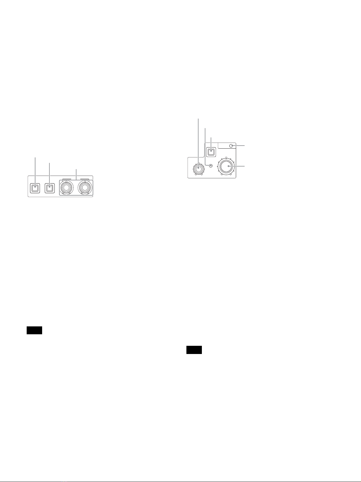
sWhite balance adjustment control block
• ATW (auto tracing white balance) button
The white balance is automatically adjusted in response to the
lighting conditions while this button is turned on and lit.
• PRESET (white balance preset) button
The white balance is automatically adjusted with a 3200K
color temperature preset value while this button is turned on
and lit.
• WHITE (white balance manual adjustment) knobs
Adjusts the white balance manually. The left knob adjusts the
R coefficient, and the right knob adjusts the B coefficient.
The adjustment can be set to relative or absolute value mode
on the <FRONT PANEL 1> page in the CCU
CONFIGURATION menu. The default value is relative value
mode.
For details, see “R/B WHITE” (page 31) on <FRONT PANEL
1> and “R/B WHITE” (page 32) on <FRONT PANEL 2>.
When the ATW button is lit, the WHITE knobs are deactivated.
tAUTO WHITE/BLACK (white balance/black balance
auto adjustment) lever
Initiates the white balance or black balance auto adjustment
function.
WHITE automatically adjusts the white balance, and BLACK
automatically adjusts the black balance.
uBLACK/FLARE (black balance/flare balance manual
adjustment) knobs and indicator
Adjusts the black balance and flare balance manually.
When the indicator is not lit, the knobs adjust the black
balance. When the indicator is lit, the knobs adjust the flare
balance. The left knob adjusts the R coefficient, and the right
knob adjusts the B coefficient.
The indicator operating mode (on/off function) can be set on
the <FRONT PANEL 1> page in the CCU CONFIGURATION
menu.
The adjustment can be set to black balance or flare balance
adjustment in relative or absolute value mode on the <FRONT
PANEL 1> page in the CCU CONFIGURATION menu. The
default value is black balance adjustment in relative value
mode.
For details, see “R/B BLACK” (page 31) on <FRONT PANEL
1> and “R/B BLACK” (page 32) on <FRONT PANEL 2>.
vIRIS/MASTER BLACK adjustment control block
• MASTER BLACK (master black adjustment) knob
Adjusts the master black manually.
The adjustment can be set to relative or absolute value mode
on the <FRONT PANEL 1> page in the CCU
CONFIGURATION menu. The default value is relative value
mode.
For details, see “M BLACK” (page 31) on <FRONT PANEL 1>
and “M BLACK” (page 32) on <FRONT PANEL 2>.
• EXT (lens extender) indicator
Turns on to indicate that the lens extender is in-use on the
camera.
• AUTO (auto iris) button
Switches the lens auto iris adjustment function on/off (button
light turns on/off). The iris is automatically adjusted in
response to the input light level.
When the button is not lit, the iris is adjusted manually.
• IRIS/MB ACTIVE (iris/master black active) indicator
Indicates, when lit, that the iris and master black controls are
active (in panel active state set by the PANEL ACTIVE button).
When the indicator is lit, the iris and master black can be
adjusted from the CCU.
The indicator is not lit when the iris and master black controls in the
RCP-1000-series Remote Control Panel are active.
• IRIS (iris adjustment) knob
When the AUTO button is not lit: Adjusts the lens iris manually.
When the AUTO button is lit: Finely adjusts the auto adjusted
iris value.
The adjustment can be set to relative or absolute value mode
on the <FRONT PANEL 1> page in the CCU
CONFIGURATION menu. The default value is absolute value
mode.
For details, see “IRIS” (page 31) on <FRONT PANEL 1> and
“IRIS” (page 32) on <FRONT PANEL 2>.
Note
WHITE
ATW PRESET
ATW (auto tracing white balance) button
WHITE (white balance manual adjustment) knobs
PRESET (white balance preset) button
Note
IRIS/MB
ACTIVE
EXT
IRIS
AUTO
MASTER BLACK
AUTO (auto iris) button
IRIS/MB ACTIVE (iris/master black active)
indicator
EXT (lens extender) indicator
MASTER BLACK (master black adjustment) knob
IRIS (iris adjustment) knob

10
Rear Panel
a“Memory Stick” slot
For service use only.
bLAN jack (RJ-45, 8-pin)
Connects to a LAN hub (10BASE-T/100BASE-TX), when
using a network connection, via a LAN cable (shielded type,
category 5 or higher).
For safety, do not connect the connector for peripheral device wiring
that might have excessive voltage to this port.
Follow the instructions for this port.
cHD PROMPTER (HD teleprompter connectors) (BNC
type)
When a camera that supports an HD teleprompter function is
connected to the CAMERA connector, the HD-SDI signal input
on this connector is output from the SDI I/O connector of the
camera.
Input an HD-SDI signal having frequency synchronization with the
camera control unit.
dSLOT2, SDI OUTPUT 1 to 4 (4K/3G/HD TRUNK output)
connectors (BNC type)
Outputs the camera signal as 12G SDI signal, 3G SDI signal,
or 1.5G signal (HD TRUNK only).
eRETURN INPUT SDI1, SDI2, VBS1, VBS2 (VBS/SDI
return video) connectors (BNC type)
Inputs the VBS return video signals (2-system), HD SDI or SD
SDI return video signals (2-system).
fAUDIO OUTPUT CH-1, CH-2 connectors (XLR 3-pin)
Outputs audio signals from the camera AUDIO 1 IN and
AUDIO 2 IN connectors.
gCAMERA connector (optical fiber connector)
Connect to the target camera or CA-FB70 HD Camera
Adaptor.
When you use an optical composite cable for connection,
power supply, all camera signals, such as control signal, video
signal and audio signals can be transmitted.
When you use only single-mode optical fiber cables for
connection, all signals (except power supply) can be
transmitted by a pair of single-mode optical fiber cables.
For details about pin assignment, see “CAMERA connector”
(page 37).
If the terminations of the single-mode optical fiber cable or optical
composite cable are contaminated with dust, etc., transmission errors
may occur. Be sure to replace the cap that came with the cable over
the termination when a cable is not in use.
hAC supply input connector
Connects to the AC supply via the specified power cord
(optional). A plug holder (optional) can be used to secure the
power cord to the CCU.
iREFERENCE (reference input) connectors (BNC type)
IN: Inputs an HD tri-level reference sync signal or SD
reference sync signal (black burst signal) for external sync.
OUT: The input signal is output from the other connector as-is
(loop-through output). If the loop-through output is not
used, it is automatically connected to a 75 Ωterminator.
jPROMPTER (teleprompter input) connectors (BNC
type)
IN: Inputs the VBS signal for the teleprompter.
OUT: The input signal is output from the other connector as-is
(loop-through output). If the loop-through output is not
used, it is automatically connected to a 75 Ωterminator.
kREMOTE connector (8-pin)
Transmits and receives control signals from the RCP-1000-
series Remote Control Panel via a CCA-5 cable (optional). It
also supplies power when connected to an RCP-1000-series
Remote Control Panel.
lVBS 1, 2 (composite video signal 1, 2) connectors
(BNC type)
Outputs (2-system) the camera signals in composite signal
format.
mSLOT1, SDI OUTPUT 1 to 4 connectors (BNC type)
Outputs the camera signals in HD SDI or SD SDI signal
format.
The SDI OUTPUT 3 and SDI OUTPUT 4 connectors can also
output signals with superimposed character or marker display.
nPIX (picture monitor output) connector (BNC type)
Outputs a video signal for a picture monitor. It can also output
a signal with superimposed character display.
oSYNC (sync signal output) connector
Outputs a sync signal for connection to the sync signal input
connector of a waveform monitor or picture monitor.
CAUTION
Note
Note

11
pINTERCOM/TALLY/PGM (intercom/tally/program
audio) connector (D-sub 25-pin)
Transmits and receives the various intercom, tally, and
program audio signals. It connects to the
intercom/tally/program audio connector of the intercom
system.
For information about pin assignment, see
“INTERCOM/TALLY/PGM connector” (page 36) in “Pin
Assignment”.
Depending on the PGM MIX LEVEL settings of the camera, PGM
signal may leak into the INTERCOM output. Turn the PGM MIX
LEVEL settings down to reduce the signal interference.
qTRUNK connector (D-sub 9-pin, RS-232C/RS-422A
standard)
Connects to an external device to provide a communication
path via the CCU between that device and another external
device connected to the TRUNK connector on the camera.
You can switch between RS-232C and RS-422A settings in the
menu.
For information about pin assignment, see “TRUNK
connector” (page 37) in “Pin Assignment”.
Note

12
Setup
Area Settings
Before using the unit
When you use this unit for the first time, area setting is
required.
Setting the area
1Turn the power on.
2Set the LOCK switch to OFF and make sure that the
PANEL ACTIVE button is not illuminated.
If the PANEL ACTIVE button lights up, press the button to
turn the light off.
3Press and hold down the SW1 and SW2 buttons at the
same time for more than two seconds.
The unit switches to setting mode and selectable setting
values appear in the SHUTTER display.
4Release the buttons after the unit switches to setting
mode.
5Select the desired area, using the UP/DOWN lever,
within five seconds after the unit switches to setting
mode.
a) NTSC composite video signal output with black setup (7.5 IRE).
System frequency: 59.94i
b) NTSC composite video signal output with no black setup. System
frequency: 59.94i
c) PAL composite video signal output. System frequency: 50i
Setting mode is deactivated unless setup starts within five
seconds after the unit switches to setting mode. Follow step 3
again to activate setting mode.
“- - - - ” appears in the SHUTTER display five seconds after
setting. Area settings are stored and the units switches to
normal mode.
Settings when Connecting with Only
Single-Mode Optical Fiber Cable
LASER DIODE (optical output) setting
When you use only single-mode optical fiber cable to connect
the HD camera adaptor to this unit, configure the optical output
setting in the unit.
Setting LASER DIODE
1Connect the unit and the HD camera adaptor by a
single-mode optical fiber cable.
2Set the POWER switch of this unit to ON.
3Display the menu.
For information about setting menu items, see “Setup
Menu” (page 19).
4Set the optical output to ON.
Display the <OUTPUT SELECT> S01 page of the
SYSTEM OPERATION menu, then set LASER DIODE to
ON.
• This setting is unnecessary when you use optical composite
cables.
• In the factory default setting, LASER DIODE is set to OFF
when this unit starts up. If you want to retain the LASER
DIODE setting you have previously set, from the CCU
CONFIGURATION menu, select <OTHERS> C14 page,
LASER DIODE ON BACKUP, then set to ENABLE.
• Use general, single-mode optical fiber cables with an LC
connector for connection. For details, contact a Sony sales
representative.
Setting Area
60i5 NTSC (except Japan) a)
60i NTSC (Japan) b)
50i PA L c)
Note
SW1, SW2 buttons
LOCK switch
POWER switch
SHUTTER display
PANEL ACTIVE button UP/DOWN lever
Notes

13
Signal Format Setting
You can set the signal format to use in the menu.
For details about menu operations, see “To display the CCU
MENU page” (page 19).
The CAMERA FORMAT settings available for selection vary
depending on the HD HDR mode setting.
For details about HD HDR mode, see “HD HDR Mode Setting”
(page 14).
HD HDR mode is set to OFF by default.
1Display the CCU MENU page.
2Display the MULTI FORMAT page of the SYSTEM
OPERATION menu.
3Refer to the following table and set FREQUENCY and
CAMERA FORMAT.
If the area setting is changed after configuring these items, the
signal format automatically switches to 1080/59.94I or 1080/50I
according to the FREQUENCY setting corresponding to the area
setting.
Output Signal Setting
You can set the SDI signal output of SLOT1 and SLOT2
connectors in the menu.
For details about menu operations, see “To display the CCU
MENU page” (page 19).
The method varies depending on the selected HD HDR mode.
For details about HD HDR mode, see “HD HDR Mode Setting”
(page 14).
When HD HDR mode is OFF
1Display the CCU MENU page.
2Display the OUTPUT FORMAT page of the SYSTEM
OPERATION menu.
3Refer to the following table and set the output signal
for each slot under SLOT-NO.
SLOT1 connector
Values in bold are valid when connected with HXC-FB80
only.
FREQUENCY CAMERA
FORMAT
Remarks
59.94Hz
(525 NTSC)
1080/59.94I NTSC/NTSC (Japan) format
1080/29.97PsF
1080/59.94P HXC-FB80 connection only
1080/23.98PsF HXC-FB80 connection only
720/59.94P
50Hz
(625 PAL)
1080/50I PAL format
1080/25PsF
1080/50P HXC-FB80 connection only
720/50P
Note
<MULTI FORMAT> S03 TOP
FREQUENCY: 59.94Hz
(525 NTSC)
CAMERA FORMAT
: 1080/59.94P
(OETF : SDR)
CAMERA
FORMAT setting
1-1&2 (SDI-1, 2)
setting
1-3&4 (SDI-3, 4)
setting
1080/59.94P
(OETF: SDR)
1080/59.94I M1080/59.94I
525/59.94I M525/59.94I
1080/29.97PsF
(OETF: SDR)
1080/29.97PsF M1080/29.97PsF
525/29.97PsF M525/29.97PsF
1080/23.98PsF
(OETF: SDR)
1080/23.98PsF M1080/23.98PsF
M525/59.94I
1080/59.94I M1080/59.94I
M525/59.94I
525/59.94I M1080/23.98PsF
M1080/59.94I
M525/59.94I
1080/50P
(OETF: SDR)
1080/50i M1080/50I
625/50i M625/50I
1080/25PsF
(OETF: SDR)
1080/25PsF M1080/25PsF
625/25PsF M625/25PsF
1080/59.94I
(OETF: SDR)
1080/59.94I M1080/59.94I
525/59.94I M525/59.94I
1080/50I
(OETF: SDR)
1080/50I M1080/50I
625/50I M625/50I
720/59.94P
(OETF: SDR)
720/59.94P M720/59.94P
525/59.94I M525/59.94I
<OUTPUT FORMAT> S04 TOP
SLOT-NO
1-1&2: 1080/59.94I
3&4: M525/59.94I
2-1&2: 4K/59.94P 2SI
3&4: 4K/59.94P 2SI
3G-SDI: LEVEL A

14
SLOT2 connector
Valid when connected with HXC-FB80 only.
a) Output as 3G-SDI. Select SMPTE 425 Level-A or SMPTE 425
Level-B.
b) Select BT.709 or BT.2020 for the color space.
c) HD-TRUNK is output.
When HD HDR mode is LIVE HDR
Valid when connected with HXC-FB80 only.
1Display the CCU MENU page.
2Display the OUTPUT FORMAT page of the SYSTEM
OPERATION menu.
3Refer to the following table and set the output signal
for each slot under SLOT-NO.
SLOT1 connector
All output signals are SDR signals.
SLOT2 connector
a) Output as 3G-SDI. Select SMPTE 425 Level-A or SMPTE 425
Level-B.
b) HDR signal is output.
c) SDR signal is output.
d) HD-TRUNK is output when HD TRUNK is set to ON.
HD HDR Mode Setting
HD HDR mode must be enabled on the unit for HD HDR
operation when the HXC-FB80 is connected to the unit.
The HXC-FB80 software must be upgraded to V1.10 or later for
operation in this mode.
1Connect the HXC-FB80 to the unit.
2Set the POWER switch of this unit to ON.
3Display the CCU MENU page.
720/50P
(OETF: SDR)
720/50P M720/50P
625/50I M625/50I
CAMERA
FORMAT setting
2-1&2 (SDI-1, 2)
setting
2-3&4 (SDI-3, 4)
setting
1080/59.94P
(OETF: SDR)
1080/59.94P a) 1080/59.94P a)
4K/59.94P SQD a) b) 4K/59.94P SQD a) b)
4K/59.94P 2SI
a) b)
4K/59.94P 2SI a) b)
4K/59.94P 12G b) 1080/59.94P a)
1080/29.97PsF
(OETF: SDR)
– 1080/29.97PsF c)
1080/23.98PsF
(OETF: SDR)
– 1080/23.98PsF c)
1080/50P
(OETF: SDR)
1080/50P a) 1080/50P a)
4K/50P SQD a) b) 4K/50P SQD a) b)
4K/50P 2SI a) b) 4K/50P 2SI a) b)
4K/50P 12G b) 1080/50P a)
1080/25PsF
(OETF: SDR)
– 1080/25PsF c)
1080/59.94I
(OETF: SDR)
– 1080/59.94I c)
1080/50I
(OETF: SDR)
– 1080/50I c)
720/59.94P
(OETF: SDR)
– 720/59.94P c)
720/50P
(OETF: SDR)
– 720/50P c)
CAMERA
FORMAT setting
1-1&2 (SDI-1, 2)
setting
1-3&4 (SDI-3, 4)
setting
<OUTPUT FORMAT> S04 TOP
SLOT-NO
1-1&2: 1080/59.94I
3&4: M1080/59.94P
2-1&2: 1080/59.94P
(OETF : HLG_LIVE)
3&4: 1080/59.94P
(OETF : SDR)
3G-SDI: Level1 A
CAMERA
FORMAT setting
1-1&2 (SDI-1, 2)
setting
1-3&4 (SDI-3, 4)
setting
1080/59.94P
(OETF:HLG_LIVE)
1080/59.94I M1080/59.94I
525/59.94I M525/59.94I
1080/50P
(OETF:HLG_LIVE)
1080/50I M1080/50I
625/50I M625/50I
1080/59.94I
(OETF:HLG_LIVE)
1080/59.94I M1080/59.94I
525/59.94I M525/59.94I
1080/50I
(OETF:HLG_LIVE)
1080/50I M1080/50I
625/50I M625/50I
CAMERA
FORMAT setting
1-1&2 (SDI-1, 2)
setting
1-3&4 (SDI-3, 4)
setting
1080/59.94P
(OETF:HLG_LIVE)
1080/59.94P
a)
b)
1080/59.94P a)
c)
1080/50P
(OETF:HLG_LIVE)
1080/50P
a)
b)
1080/50P a)
c)
1080/59.94I
(OETF:HLG_LIVE)
1080/59.94I
b)
1080/59.94I
c) d)
1080/50I
(OETF:HLG_LIVE)
1080/50I
b)
1080/50I
c) d)
Note

15
4Change the <HD HDR> (S07) setting in the SYSTEM
OPERATION menu to LIVE HDR.
5Move the cursor to YES under MODE CHANGE OK?,
and press the CONTROL button.
The unit restarts.
LIVE HDR operation is enabled after restarting.
• 4K signal output is disabled when the HD HDR mode is set to LIVE
HDR.
For details, see “Output Signal Setting” (page 13).
• The signal format of the connected camera and output signal format
change automatically when the HD HDR mode is changed.
- When the mode is switched from OFF to LIVE HDR, the format
changes to 1080P HDR from 1080P format, or to 1080I HDR from
formats other than 1080P.
- When the mode is switched from LIVE HDR to OFF, the format
changes to 1080P from 1080P HDR format, or to 1080I from
formats other than 1080P HDR.
Notes
<HD HDR> S07 TOP
HDR MODE : cOFF
SDR GAIN : ------
HDR BLACK OFFSET: -----
<HD HDR> S07 TOP
MODE CHANGE OK? cYES NO
HDR MODE :?OFF
cLIVE_HDR
SDR GAIN : ------
HDR BLACK OFFSET: -----

16
Status Display
The CCU system status can be monitored using a picture
monitor connected to the PIX output.
For details about checking and changing settings, see “Setup
Menu” (page 19).
Displaying the Status Screen
The status screen is controlled using the knob and levers in
the MENU control block on the front panel.
To display the status screen
Set the DISP/MENU lever to the DISP position.
The most recently viewed status screen page is displayed
(when first powered on, the camera settings page is
displayed).
Turning the CONTROL knob changes the displayed page.
To exit the status screen display
In status screen display mode, set the DISP/MENU lever to the
DISP position.
Status Display Screen
The following information is displayed on the status display
screen.
• Camera settings
•Systemstatus
• CCU hardware diagnostics
• Camera system diagnostics
• Network diagnostics
• CCU AT board diagnostics
• CCU DPR board diagnostics
• Front panel diagnostics
• Camera hardware diagnostics
• ROM version information for major components
Camera settings
Page 1
aGain value indicator
Displays the video output signal gain (dB units).
Becomes the AGC indicator when AGC is on.
bShutter speed/Clear scan frequency indicator
Displays the shutter speed. When ECS is on, the clear scan
frequency is displayed.
At slow shutter speeds, the number of frames is displayed. In
auto shutter mode, AE (Auto Exposure) is displayed.
cShutter/ECS/Slow shutter on/off indicator
Displays the shutter/ECS/slow shutter on/off state.
dCamera auto control information area
Top: Displays the Auto Setup category and execution status.
Bottom: Displays the execution item.
eND filter indicator
Displays the current ND filter selection.
fF-stop value indicator
Displays the lens F-stop value (iris value).
gEX (lens extender) indicator
Displayed when the lens extender is in use.
• Items that are turned off using the <DISPLAY> page settings of the
CCU CONFIGURATION menu are not displayed.
• A “-” mark is displayed for each item when a camera is not
connected.
hCC filter indicator
Displays the current CC filter selection.
Page 2
White: White balance R/G/B value
Black: Black balance R/G/B/Master value
BLK γ:Black gamma value
MENU ENTER
CONTROL
DISP CANCEL
MENU
DISP/MENU lever and indicator
CONTROL knob
Notes
6
dB
1/2000 OFF
ND:1 F:4.7 EX CC:A
a
ef hg
b
cd
6
dB
1/2000 OFF
White Black
R: 0 R: 0
G: 0 G: 0
B: 0 B: 0
M:0.0
BLK γFlare
: 0 R: 0
DTL G: 0
: 0 B: 0
ND:1 F:4.7 EX

17
Flare: Flare balance R/G/B value
DTL: Detail level
The items are the same as those on “Page 1” (page 16) in the
“Camera settings” section.
System status
The camera model name, format, and camera OETF
(HLG_LIVE or SDR) are displayed at the top of the page when
a camera is connected to the unit. A “---” mark is displayed
when a camera is not connected.
Reference: Reference signal format and lock status
SLOT1-1&2: SLOT1 SDI OUTPUT 1/2 connector output
format selection
SLOT1-3&4: SLOT1 SDI OUTPUT 3/4 connector output
format selection
SLOT2-1&2: SLOT2 SDI OUTPUT 1/2 connector output
format selection and connected camera OETF (HLG_LIVE
or SDR) indicator
SLOT2-3&4: SLOT2 SDI OUTPUT 3/4 connector output
format selection and connected camera OETF (HLG_LIVE
or SDR) indicator
Return-1: Return channel setting of Return 1
Return-2: Return channel setting of Return 2
Return-3: Return channel setting of Return 3
Return-4: Return channel setting of Return 4
CCU hardware diagnostics
The camera Auto Setup category, and the corresponding
setup item and status are displayed at the top of the page.
DPR: DPR board status
AT: AT board status
Front Panel: Front panel status
Camera system diagnostics
Page 1
CAMERA: Camera light sensor status
CCU: CCU light sensor status
Fan Power: CCU power supply fan status
Timer: Elapsed time since power-on
CCU Power: CCU power supply status
SerialNo: CCU serial number
Page 2
CAMERA Cable: Camera cable connection status
CAMERA Data: Camera data transmission status
CAMERA Power: Camera power supply status
REMOTE Cable: Remote device cable connection status
REMOTE Data: Remote device data transmission status
REMOTE Power: Remote device power supply status
CAM/CCU (light sensor level indicator): CAM displays
camera light sensor level, and CCU displays CCU light
sensor level.
Page 3
Intercom CCU FRONT: CCU intercom selection
Intercom CAMERA: Camera intercom channel selection and
microphone status
CAM MIC Gain CH1 (FRONT): Amplifier gain for a
microphone connected to the camera AUDIO 1 IN
connector.
Note
*System Status 1/2*
HXC-FB80 1080/59.94P
(OETF : HLG_LIVE)
Reference:Free Lock
SLOT1-1&2:1080/59.94I
SLOT1-3&4:1080/59.94I
SLOT2-1&2:4K/59.95P 2SI
(OETF : HLG_LIVE)
SLOT2-3&4:4K/59.95P 2SI
(OETF : SDR)
*System Status 2/2*
HXC-FB80 1080/59.94I
(OETF : HLG_LIVE)
Return-1 :SDI-1(HD)
Return-2 :SDI-2(SD)
Return-3 :VBS-1
Return-4 :FBS-2
*Diagnosis* 3/14
DPR :OK
AT :OK
Front Panel : OK
*System Diag 1/3* 4/14
Optical Condition
CAMERA OK
CCU OK
Fan Power OK
Timer 0H
CCU Power OK
SerialNo 00000000
*System Diag 2/3* 5/14
CAMERA Cable Connect
Data OK
Power OK
REMOTE Cable Connect
Data OK
Power OK
CAM
:ssxxxxxxb
Green
CCU
:ssxxxxxxb
Green
*System Diag 3/3* 6/14
Intercom
CCU FRONT ENG
PGM ON
CAMERA ENG
MIC ON
CAM MIC Gain
CH1(FRONT) 60
dB
CH2(REAR) 60
dB
SUB CMD --------

18
CAM MIC Gain CH2 (REAR): Amplifier gain for a microphone
connected to the camera AUDIO 2 IN connector.
Network diagnostics
Page 1
MacAddress: MAC address stored in CCU EEPROM
Auto Negotiation: Auto negotiation setting
Connection Speed: Connection speed setting
Duplex Mode: Communication method setting
Link Status: Network connection status
Page 2
CNS Mode: REMOTE and LAN connectors mode setting
CCU No.: CCU number setting
Page 3
IP Address: CCU IP address setting
Subnet Mask: CCU subnet mask setting
Default Gateway: CCU default gateway setting
CCU AT board diagnostics
SLOT2-1&2: SLOT2 SDI OUTPUT 1/2 connector output
format selection
SLOT2-3&4: SLOT2 SDI OUTPUT 3/4 connector output
format selection
SDI OUT STATUS: SLOT2 SDI OUTPUT1/2/3/4 status
PLD Status: PLD status
PLD AT: AT-PLD version
AT POWER: AT board power supply status
CCU DPR board diagnostics
Reference: Reference signal setting
HD CB: HD color bar setting
SD CB: SD color bar setting
PLD Status: PLD status
PLD SY: SY-PLD version
PLD POST: POST-PLD version
IIC: IIC bus control status
DPR POWER: DPR board power supply status
Front panel diagnostics
Assignable/Custom SW1: Function assigned to the SW1
button
Assignable/Custom SW2: Function assigned to the SW2
button
Assignable/Custom VOLUME: Function assigned to the
CUSTOM knob
SW Bright: Button lights LED brightness setting
IIC: IIC bus control status
*Network Diag 1/3* 7/14
MacAddress:000000-000000
Auto Negotiation: ON
Connection Speed:100M
Duplex Mode :HALF
Link Status :OK
*Network Diag 2/3* 8/14
CNS Mode :BRIGDE
CCU No. :1
*Network Diag 3/3* 9/14
IP Address
0. 0. 0. 0
Subnet Mask
0. 0. 0. 0
Default Gateway
0. 0. 0. 0
*AT Diag* 10/14
SLOT2-1&2:4K/59.94P 2SI
SLOT2-3&4:4K/59.94P 2SI
SDI OUT:1 2 3 4
STATUS1 OK OK OK OK
STATUS2 OK OK OK OK
PLD Status :OK
AT :1.00
AT POWER :OK
*DPR Diag* 11/14
Reference :HD
4K/HD CB
:BAR 16:9(100%)
SD CB :SMPTE
PLD Status:OK
SY :1.00
POST :1.00
IIC :OK
DPR POWER:OK
*Front Panel Diag* 12/14
Assignable/Custom
SW1 :CAM POWER
SW2 :5600K
VOLUME :SD DTL Level
SW Bright:Normal
IIC :OK

19
Camera hardware diagnostics
Displays the camera hardware status.
ROM version information
CAMERA: Camera model name and ROM version
CCU: CCU model name and ROM version
Setup Menu
The CCU system and peripheral settings can be checked and
modified using a picture monitor connected to the PIX output.
Changing Menu Item Settings
The menu screen is controlled using the knob and levers in the
MENU control block on the front panel.
Setting the CANCEL/ENTER lever to the ENTER position and
pressing the CONTROL knob perform the same function.
To display a menu page
Set the DISP/MENU lever to the MENU position.
When first powered on, the CCU MENU page is displayed.
To display the CCU MENU page
In menu display mode, turn the CONTROL knob to move the
pointer (,) to TOP in the upper right corner of the menu page,
then press the CONTROL knob.
The CCU MENU showing the menu configuration is displayed.
To select an item in the CCU MENU
Turn the CONTROL knob to move the pointer (,) up/down to
the desired menu item, then press the CONTROL knob.
The most recently viewed page in the selected menu is
displayed.
*CAMERA Diag* 13/14
ALL BOARD OK
*ROM Version* 14/14
CAMERA HXC-FB80
1.00 XX.XX.XX
CCU HXCU-FB80
1.00 XX.XX.XX
Menu name Description
SYSTEM OPERATION Input/output signal format and
system-related settings
CCU CONFIGURATION CCU configuration settings
NETWORK SETTINGS Network-related settings
MENU ENTER
CONTROL
DISP CANCEL
MENU
DISP/MENU (display/menu) lever and indicator
CANCEL/ENTER lever
CONTROL knob
** CCU MENU **
cSYSTEM OPERATION
CCU CONFIGURATION
NETWORK SETTINGS

20
To change the displayed page
1Turn the CONTROL knob to move the pointer (,) to
the page number, then press the CONTROL knob.
The pointer (,) changes to a flashing question mark (?).
2Turn the CONTROL knob to change the displayed
page to the desired page, then press the CONTROL
knob.
The question mark (?) changes back to the pointer (,).
Items on the page can now be selected and changed.
To change a menu item setting
If a question mark (?) is displayed beside the page number,
press the CONTROL knob to restore the pointer (,). Items
on the page can now be selected and changed.
1Turn the CONTROL knob to move the pointer (,) to
the desired item, then press the CONTROL knob.
The pointer (,) changes to a flashing question mark (?).
2Turn the CONTROL knob to change the setting.
To cancel a changed setting
Set the CANCEL/ENTER lever to the CANCEL position
before pressing the CONTROL knob. The item is restored
to its current setting.
To suspend menu changes
Set the DISP/MENU lever to the MENU position to exit the
menu screen.
The DISP/MENU lever can be set to the MENU position
again to restart the operation.
3Press the CONTROL knob.
The question mark (?) changes back to the pointer (,),
and the item setting is registered.
4Repeat steps 1 to 3 to change other settings on the
same page.
To enter a character string
Some menu items require a character string input.
Moving the pointer (,) to an item with a character string input
and pressing the CONTROL knob displays a rectangular
cursor and a list of selectable characters.
Turning the CONTROL knob moves the cursor between
characters.
The following menu item has character strings:
• CCU CONFIGURATION menu t<BAR CHARACTER>
page tBAR CHARACTER
1Move the text cursor to the input position, then press
the CONTROL knob.
A second cursor is displayed in the character list.
2Turn the CONTROL knob to move the cursor to the
desired character, then press the CONTROL knob.
Repeat steps 1and 2to enter other characters.
• Select INS to insert a space character at the cursor
position.
• Select DEL to delete the character at the cursor
position.
• Select RET to return to step 1without changing the
string.
• Entering the maximum number of characters (up to the
right edge) moves the cursor to ESC on the lower right
of the character list.
3Turn the CONTROL knob to move the cursor to END,
then press the CONTROL knob.
The new input string is registered.
To cancel the character string setting
Turn the CONTROL knob to move the cursor to ESC, then
press the CONTROL knob.
To exit the menu display
In menu display mode, set the DISP/MENU lever to the MENU
position.
<OUTPUT SELECT> ?S01 TOP
OUTPUT:*CAMERA
BAR
TEST1
TEST2
PIX:*ENC R G B
R&B G&B R&B RGB
LASER DIODE: (ON)
Flashing
Table of contents
Other Sony Control Unit manuals
Popular Control Unit manuals by other brands

System Sensor
System Sensor M500FP Installation and maintenance instructions

Raytheon Electronics
Raytheon Electronics AUTOHELM Z235 Bidata Round Service manual

Festo
Festo MS6 SV E 10V24 Series operating instructions

Hoft & Wessel
Hoft & Wessel HW 86012 Firmware manual

Isenberg
Isenberg TVH.2705F installation manual

Saftronics
Saftronics DG2 PLUS Series manual