AVERTISSEMENT : POUR ÉVITER
UNE BLESSURE OU UN DOMMAGE À
L’ÉQUIPEMENT, SEULS LES DISTRIBUTEURS
RELIANCE® AUTORISÉS DEVRAIENT
INSTALLER OU DÉPLACER L’ÉQUIPEMENT.
WARNING: TO PREVENT FIRE OR
ELECTRICAL SHOCK HAZARD, DO NOT
EXPOSE THIS EQUIPMENT TO RAIN OR
MOISTURE.
AVERTISSEMENT : POUR ÉVITER UN
INCENDIE OU UN RISQUE DE CHOC
ÉLECTRIQUE, N’EXPOSEZ PAS CET
ÉQUIPEMENT À LA PLUIE OU À L’HUMIDITÉ.
WARNING- TO AVOID PERSONAL INJURY
OR DAMAGE TO THE EQUIPMENT, ONLY
TRAINED/QUALIFIED PERSONNEL WHO
HAVEREAD THISMANUAL SHOULDOPERATE
THIS EQUIPMENT. OPERATION BY UNAU-
THORIZED USERS SHOULD BE PREVENTED.
AVERTISSEMENT : POUR ÉVITER
UNE BLESSURE OU UN DOMMAGE À
L’ÉQUIPEMENT, SEUL DU PERSONNEL
ENTRAÎNÉ/QUALIFIÉ QUI A LU CE MANUEL
DEVRAIT FAIRE FONCTIONNER CET
ÉQUIPEMENT. LE FONCTIONNEMENT
PAR DES UTILISATEURS NON AUTORISÉS
DEVRAIT ÊTRE ÉVITÉ.
WARNING- TO AVOID PERSONAL INJURY OR
DAMAGE TO THE EQUIPMENT, CALL YOUR
AUTHORIZED RELIANCE® DISTRIBUTOR OR
THE TECHNICAL SERVICE DEPARTMENT IF
ANYPART OFTHE EQUIPMENTFAILS. ONGO-
ING USE OF MALFUNCTIONING EQUIPMENT
IS NOT RECOMMENDED.
AVERTISSEMENT : POUR ÉVITER
UNE BLESSURE OU UN DOMMAGE À
L’ÉQUIPEMENT, APPELEZ VOTRE
DISTRIBUTEUR RELIANCE® AUTORISÉ OU
LES SERVICES TECHNIQUES SI UNE PARTIE
QUELCONQUE DE L’ÉQUIPEMENT TOMBE
EN PANNE. L’UTILISATION CONTINUE D’UN
ÉQUIPEMENT DÉFAILLANT N’EST PAS
RECOMMANDÉE.
IN-7900 5
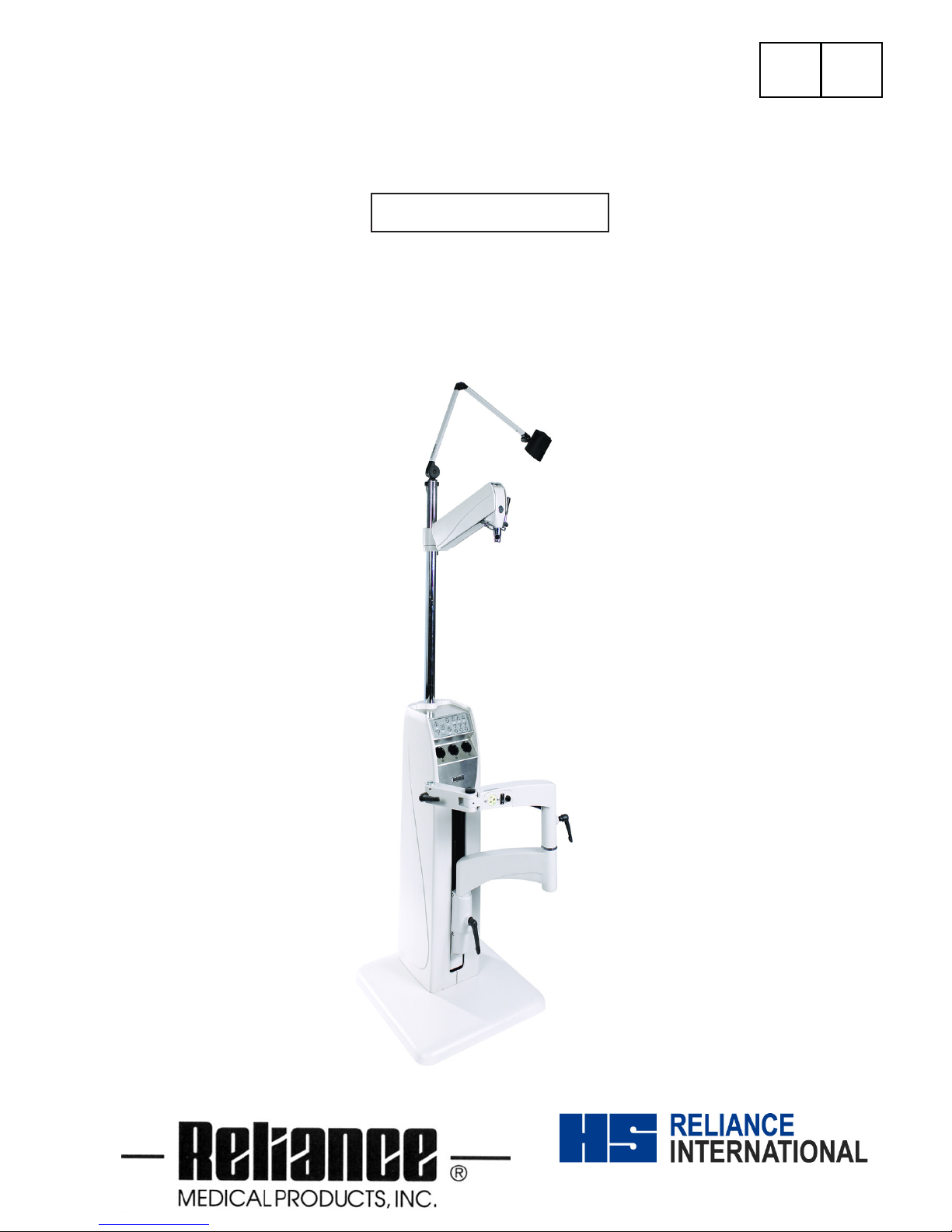
1. INTRODUCTION
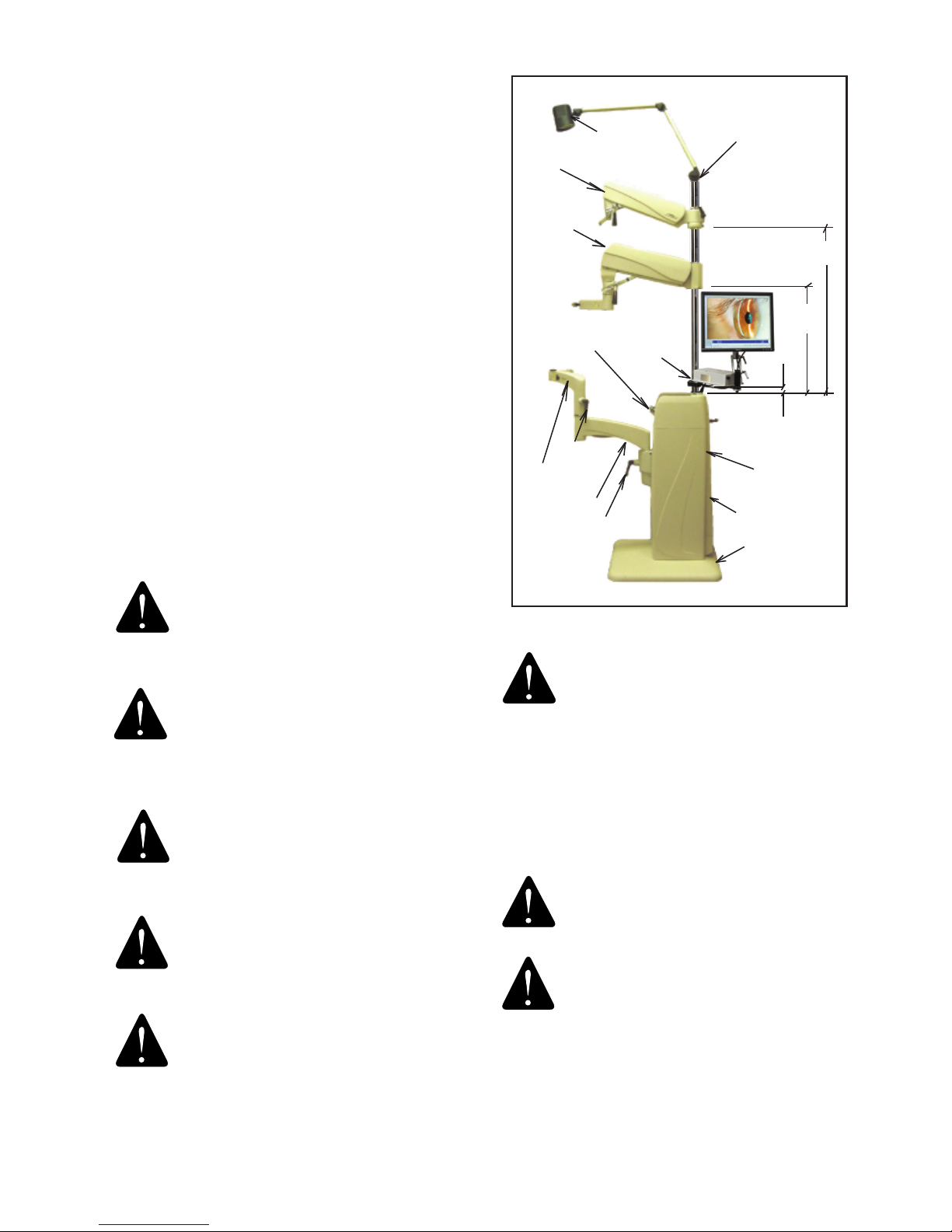
1.1. This Installation and Operating Instruction contains
information applicable only to the Reliance® Model 7900
Ophthalmic Instrument Stand also known as Floor Unit.
1.2. Should your product not perform properly, or if you
have any questions concerning the use and care of any
Reliance® product, contact the
Authorized
Reliance®
Distributor where you purchased this product or contact the
Technical Service Department, Reliance® Medical Products,
Inc., 3535 Kings Mills Road, Mason, Ohio 45040-2303, or
call (800) 735-0358.
NOTE: Always have the model number and serial
number available before contacting Reliance® or
your Authorized Reliance® Distributor.
REMARQUE : Ayez toujours le numéro de
modèle et le numéro de série à portée de la
main avant de contacter Reliance® ou votre
distributeur Reliance® autorisé.
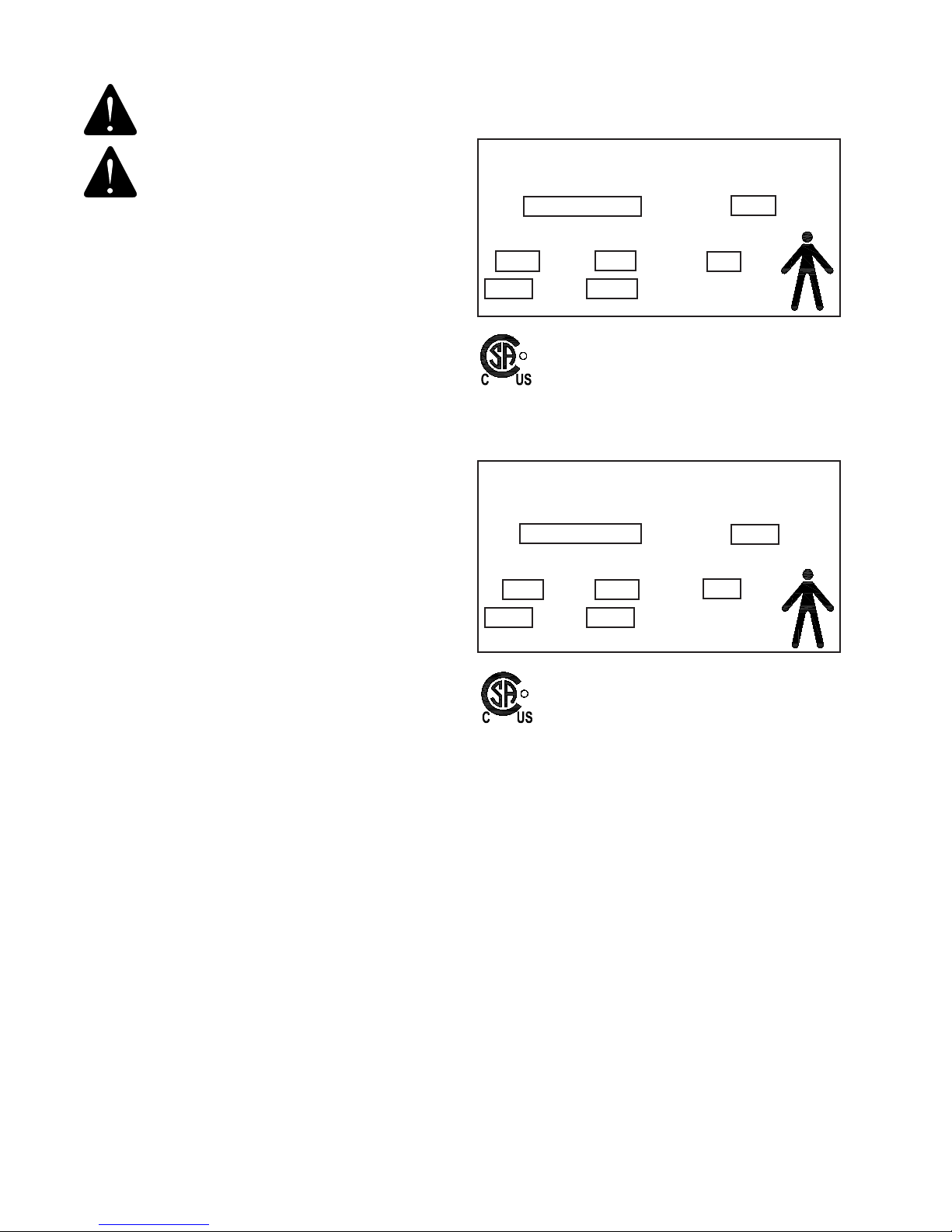
“CLASSIFIED BY CANADIAN STANDARDS
ASSOCIATION® CSA WITH RESPECT TO
ELECTRIC SHOCK, FIRE AND MECHANICAL
HAZARDS ONLY IN ACCORDANCE WITH IEC
60601-1.”
According to Clause 5 in IEC 60601-1, sec 6.8.1, this Unit
is classied by the following:
• The type of protection against electric shock:
EQUIPMENT energized from an external electrical power
source: CLASS I EQUIPMENT
• The degree of protection against electric shock: TYPE
B EQUIPMENT
• The degree of protection against harmful ingress of
water: ORDINARY DEGREE
• The degree of safety of application in the presence of a
FLAMMABLE ANESTHETIC MIXTURE WITH AIR or WITH
OXYGEN OR NITROUS OXIDE: EQUIPMENT not suitable
for use in the presence of a FLAMMABLE ANESTHETIC
MIXTURE WITH AIR or WITH OXYGEN OR NITROUS OXIDE
• The mode of operation: CONTINUOUS OPERATION
WARNING: TO AVOID PERSONAL INJURY
OR DAMAGE TO THE EQUIPMENT, ONLY
AUTHORIZED RELIANCE® DISTRIBUTORS
SHOULD INSTALL OR MOVE THE EQUIPMENT.