manuals.online logo
Brands
  1. Home
  2. •
  3. Brands
  4. •
  5. Remote Solutions
  6. •
  7. Door Opening System
  8. •
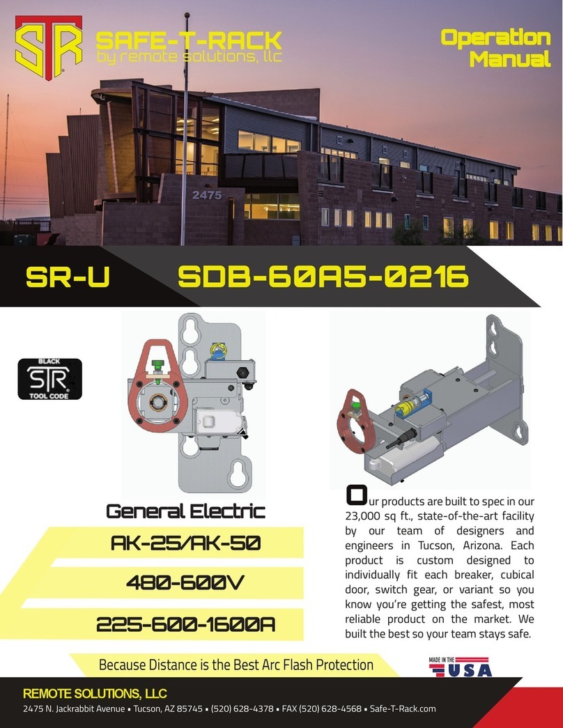
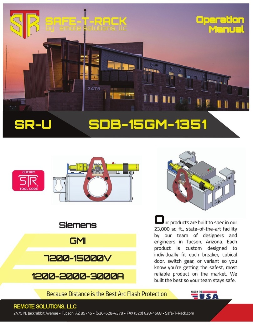
  9. Remote Solutions SAFE-T-RACK SR-U User manual

Remote Solutions SAFE-T-RACK SR-U User manual

Operation
Manual
Micro-Rupter
©
Because Distance is the Best Arc Flash Protection
2400-7200kV
200-400A
SDB-MR-LBS
SR-U
Our products are built to spec in our
23,000 sq ft., state-of-the-art facility
by our team of designers and
engineers in Tucson, Arizona. Each
product is custom designed to
individually fit each breaker, cubical
door, switch gear, or variant so you
know you’re getting the safest, most
reliable product on the market. We
built the best so your team stays safe.
Powercon
REMOTE SOLUTIONS, LLC
2475 N. Jackrabbit Avenue • Tucson, AZ 85745 • (520) 628-4378 • FAX (520) 628-4568 • Safe-T-Rack.com
Portable Kit includes: One Motor
Drive Unit (MDU), one 50’ comm.
cable, two 28V batteries, and one
SR-U Handheld Controller (HHC)
The Smart Drive Bracket (SDB)
uses the Tool Adapter Assembly
(TAA) to engage with the breaker
and perform the racking in/out
functions.
23
Part/Image Quantity Description
1 each
1 each
©©
Always observe all safety precautions and use all personal protective equipment
(PPE) as required by Local Site Procedures. This equipment is designed to minimize
exposure risk to the operator. Please use the cables, explained below, to attain
a safe distance from the breakers during racking. Always use appropriate PPE.
Above all, adhere to site specific regulations and requirements.
Before beginning the racking process, be sure that the breaker is open, verify that
a lockout/tag out is in place (LOTO) and allows racking of the breaker.
2
Depicted in figs. 1.1 and 1.2, the Smart
DriveBracket(SDB)hangsontwoShoulder
Nuts to align a Intermediate Tool Adapter
(ITA) with the open/close lever. The SDB
operates a transmission connected to the
ITA, which engages with the open/close
lever.
Once the SDB is in place, a Motor Drive
Unit (MDU) couples with a Universal Tool
Adapter Assembly (UTAA), depicted in
yellow, to engage with the transmission
and activate the open/close function. This
can be performed by the operator at a
distance up to 150 feet.
Fig. 1.2
Fig. 1.1
Sequence Process
1. Pull back the collar on the MDU.
2. Insert the UTAA in to the quick-
connect tool coupling.
3. Release the collar, twist the UTAA
to ensure it’s locked in place.
45
As noted in the Overview, the SDB is equipped with a Universal Tool Adapter Assembly
(UTAA). The Motor Drive Unit (MDU) is equipped with a quick-connect tool coupling, which
uses a collar that slides back for the UTAA to be inserted into the coupling. When the
coupling is released, the UTAA is secured in place.
Sequence Process
1. Attach a fully charged battery to
the MDU.
2. Set the locking pin to the open
position.
3. Insert the MDU equipped with the
UTAA through the mounting rings.
4. Align and engage the UTAA with
the transmission.
5. Release the locking pin, securing
the MDU in place.
6. Connect the SDB Automation
Cable to the MDU.
©
Sequence Process
1. Before mounting, set the SDB to the
locked position.
2. Hang the SDB on the Shoulder Nuts,
aligning the Intermediate Tool
Assembly and the open/close lever.
3. Release the locked SDB with the
horizontal arm, engaging the ITA and
the lever.
©
The Portable Kit includes two 28V batteries. Before connecting the battery to the system,
make sure the battery is fully charged and is attached to the MDU. If preferred, an AC Power
Supply is available, negating the need of a battery.
The MDU intuitively fits into the SDB mounting rings (depicted in red), on top of which
is a locking pin (depicted in green, fig. 1.5). Set the locking pin to the open position. Insert
the MDU and align the UTAA with the SDB transmission, then lock the MDU into place
by releasing the locking pin. When the pin fully engages, the MDU is secure.
Once the MDU is secured to the SDB and fully connected to the Tool Adapter, connect the
50-foot SDB Automation Cable to the Motor Drive Unit.
Fig. 1.5
The SDB is mounted on two slide hinges. Before hanging the SDB, using the mounting
rings, depicted in red, hold the vertical handle and pull the bracket into the locked position.
Then lift the SDB into place, mounting it on the two Shoulder nuts. Once hung, using the
horizontal lever, release the SDB and fix the Intermediate Tool Adapter to engage with the
open/close lever. Once engaged, the SDB is in place.
Fig. 1.3 Collar
←
Fig. 1.4
Intermediate
Tool Adapter
←
©©
6 7
The Handheld Controller connects to the MDU via a 50’ Automation Cable. If necessary
three cables may be tethered to achieve a safe distance of 150’. Once plugged in and
turned on, the Handheld Controller guides the user through the racking in/out procedure.
When racking in/out, if an obstruction or mechanism
failure occurs, the system will attempt to recover the
breaker to a safe position. Actions will be displayed
with an asterisk (*) in front of them. When done, the
position of the breaker will be displayed as determined by the recovery. Note the
location and approach with caution. Determine the cause of the failure and remedy
the situation prior to attempting additional remote racking.
NOTE: Attempting to stop or shutting down the system mid-process once it has started
is not recommended, as this will leave the breaker in an unknown position. The Remote
Racking System will only operate from “known” positions: connect or disconnect. The Remote
Racking System will not engage when the breaker is at a mid-point.
Remote Solutions, LLC
2475 N. Jackrabbit Avenue
Tucson, AZ 85745
(520) 628-4378
[email protected]
www.safe-t-rack.com
To get the most years of use from the Portable Kit and the Smart Drive Bracket, store the
tools in the provided polymer case in a dry, temperate environment. The tools are weather
resistant but should be used with care in rain and snow.
For any questions, concerns, information, or
missing/replacement parts, contact Remote
Solutions below or follow the QR link to our
website.
Sequence Process
1. Connect the Handheld Controller with the 50’
Comm. Cable.
2. Move a safe distance from the breaker.
3. Twist the E-Stop switch, depicted here, to acti-
vate the HCC.
4. Turn on the Handheld Controller and follow the
on-screen prompts.

This manual suits for next models

1

Other Remote Solutions Door Opening System manuals

Remote Solutions SR-U SDB-60A5-0216 User manual

Remote Solutions

Remote Solutions SR-U SDB-60A5-0216 User manual

Remote Solutions SAFE-T-RACK SR-U User manual

Remote Solutions

Remote Solutions SAFE-T-RACK SR-U User manual

Popular Door Opening System manuals by other brands

Dormakaba ED50 quick start guide

Dormakaba

Dormakaba ED50 quick start guide

Synergy Hardware S800 Series Fixing instructions

Synergy Hardware

Synergy Hardware S800 Series Fixing instructions

SECO-LARM SD-998C-D3Q installation manual

SECO-LARM

SECO-LARM SD-998C-D3Q installation manual

GEZE Guide rail Boxer P installation instructions

GEZE

GEZE Guide rail Boxer P installation instructions

Pamex KT-WRP Installation instruction

Pamex

Pamex KT-WRP Installation instruction

D+H ZA 35-BSY+(-HS) manual

D+H

D+H ZA 35-BSY+(-HS) manual

Lamp FM150PRO installation manual

Lamp

Lamp FM150PRO installation manual

CAMDEN CM-300 installation instructions

CAMDEN

CAMDEN CM-300 installation instructions

Dormakaba ED100 installation instructions

Dormakaba

Dormakaba ED100 installation instructions

argenta PIVOTICA PRO 100 F0 manual

argenta

argenta PIVOTICA PRO 100 F0 manual

Dorex 441 Installation

Dorex

Dorex 441 Installation

CornellCookson FS-500EP Series Installation instructions and operation manual

CornellCookson

CornellCookson FS-500EP Series Installation instructions and operation manual

Ryobi D-4550 Series installation instructions

Ryobi

Ryobi D-4550 Series installation instructions

Nabco Acusensor 3 instruction manual

Nabco

Nabco Acusensor 3 instruction manual

Excel XL8800 Series quick start guide

Excel

Excel XL8800 Series quick start guide

GEZE TS 5000 Recommended Settings

GEZE

GEZE TS 5000 Recommended Settings

Tucker Auto-Mation SW10 installation guide

Tucker Auto-Mation

Tucker Auto-Mation SW10 installation guide

Dormakaba RTS88 installation instructions

Dormakaba

Dormakaba RTS88 installation instructions

manuals.online logo
manuals.online logoBrands
  • About & Mission
  • Contact us
  • Privacy Policy
  • Terms and Conditions

Copyright 2025 Manuals.Online. All Rights Reserved.