manuals.online logo
Brands
  1. Home
  2. •
  3. Brands
  4. •
  5. Dorex
  6. •
  7. Door Opening System
  8. •
  9. Dorex 441 User manual

Dorex 441 User manual

A
1 11/16"
[42.9]
1 1/16"
[27]
5/16"
[8]
3/8"
[9.5]
2 11/32"
[59.5]
_
+
TOOLS REQUIRED METAL WOOD Sex Nut and Bolt
Check building and fire codes to
see if your application requires
the use of sex nuts and bolts.
LATCH VALVE
REAR BACKCHECK VALVE
(See Step 3)
CLOSING / SWEEP
VALVE
BACKCHECK VALVE CLOSER BODY
POWER ADJUSTMENT
EXTRA DUTY ARM
COVER INSERT
INSERT CUTOUTS
CLOSER COVER
SCREW PACK
#7
1/4"-20
3/16"
HINGE
PIVOT
DOOR
FRAME DOOR STOP
EXTRA DUTY ARM
8-1/16" (205 mm)
9-13/16" (249 mm) up to 110°
up to 160°
Door Opening
Dim."A"
Page 1
Door closers should NOT be installed on the exposed side (weather side) of exterior doors
Use self-drilling screws for
wood and metal doors and
frames
For wood screws, drill
3/16” hole
For machines screws
drill (#7) and tap for 1/4 -20
thread
COMPONENTS
1. MARK AND DRILL ARM PLATE HOLES (Door opens to the outside, RH shown)
441 DOOR CLOSER INSTALLATION WITH ARM441E (Extra Duty Arm)
Locate the arm plate according to the required degree of door opening, using the table
below. Mark/drill/tap the 1/4-20 holes for the arm plate on the frame soffit and /or rabbet.
ARM441E-INST 2022-04
Left Hand Right Hand
DOOR HANDING
Outside
(Pull Side)
Outside
(Pull Side)
Inside
(Push Side)
Inside
(Push Side)
ARM PLATE
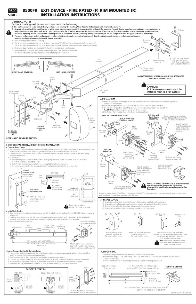
GENERAL NOTES
1. Consult installation instructions supplied with door closer
2. Hollow metal doors and hollow metal frames require reinforcement in the areas of the door closer and arm
plate mounting
3. Through bolts with sex nuts must be used in wooden Fire Door applications and on hollow metal doors with
no local reinforcement
4. Threaded holes in door or frame require a minimum 12 GA (0.110”) thickness
5. Indicated dimensions are based on industry standard door and frames with 1/8” (3 mm) clearance and 5/8”
(16 mm) stop height and properly leveled doors and frames.
6. Select the door closer and arm plate positions based on the door opening angle
7. If a drop plate is used, ensure door closer mounting screws do not protrude beyond the back surface of the
drop plate. Screws must engage a minimum of 3 threads inside the drop plate
8. For a door closer to operate properly, the arm must be positioned and operate horizontally and the door must
be supported on ball bearing hinges of sufficient size for the door used.
9. Perform a operational test on the door and adjust door closer as indication in the installation instructions
supplied with the door closer
For through bolt installations,
drill 9/32” hole through door on
the closer side and 3/8” hole on
the other side through door skin
for hollow metal doors. For wood
doors drill through 3/8” hole.
15/16"
[23.7]
1 1/2"
[38.1]
8 1/4"
[209.6]
1 1/2"
[38.1] 3/4"
[19.2]
2 5/16"
[58.7]
2 1/4"
[57]
1"
[25.4]
1"
[25.4]
3"
[76.2]
C
B
EXTRA DUTY ARM
7" [178]
8" [203]
9-3/4" [248] 8-3/4" [222]
up to 180°
up to 110°
Note: Drop plate works with a minimum top rail of 2 1/2".
Page 2
2. MARK AND DRILL DOOR MOUNTING HOLES (Door opens to the outside, RH shown)
4. DOOR CLOSER INSTALLATION (with Drop Plate Option)
3. DOOR CLOSER AND ARM INSTALLATION
441 DOOR CLOSER INSTALLATION WITH ARM441E (Extra Duty Arm)441 DOOR CLOSER INSTALLATION WITH ARM441E (Extra Duty Arm)
Locate the door closer mounting holes according to the required degree of
door opening, using the table below. Mark, drill and tap the 1/4-20 holes on
the door.
Prepare door closer mounting holes using Dim “B” or for Drop Plate using
Dim “C”.
Dim “B”
Door Closer
Dim “C”
Drop Plate
Door
Opening
Drop Plate
Holes
Door Stop
Soffit
Door Closer
Holes
1. Orientate door closer with tube end facing the door lock side
2. Before installation, screw-in the rear backcheck valve (the valve facing the door surface).
3. Attach door closer to door using qty 4 screws, (wood screws or machine screws)
4. If drop plate is used, attach drop plate to door using qty 4 screws, (wood screws or machine
screws) and door closer to drop plate using 4 machine screws.
5. Attach arm plate to soffit using 4 screws. Install a fifth screw with spacer block if or additional
support, if soffit width is narrow
6 Using a wrench on the door closer bottom shaft, turn the shaft towards the hinge about 30°
(for pre-loading), and place main arm on the closer top shaft. Insert the main arm screw into
the top shaft and tighten.
7. Rotate the arm on the closer shaft, so that the main arm is approximately parallel to the door
and ensuring that the arm elbow clears the door surface by about 1/4” to 1/2” (6 mm to 13
mm).
8. Test door closer and door operation
9. Install door closer cover.
30°
PRELOAD
30°
PRELOAD
WRENCH
1/4” TO 1/2”
(6mm TO 13 mm)
Tube
Frame Rabbet
Arm Plate
5th hole
spacer block
Soffit
5th hole in bracket plate is used with
spacer block if frame has a narrow soffit
5th hole in arm plate is used with spacer
block if frame has a narrow soffit
Frame Top Jamb
Door
ARM441E-INST 2022-04

Other Dorex Door Opening System manuals

Dorex 1901 User manual

Dorex

Dorex 1901 User manual

Dorex 1901 Series User manual

Dorex

Dorex 1901 Series User manual

Dorex DX2 PC User manual

Dorex

Dorex DX2 PC User manual

Dorex 441C Series User manual

Dorex

Dorex 441C Series User manual

Dorex 1900 Series User manual

Dorex

Dorex 1900 Series User manual

Dorex DX1 PV/FV User manual

Dorex

Dorex DX1 PV/FV User manual

Dorex DX2 PW User manual

Dorex

Dorex DX2 PW User manual

Dorex 9500 Series User manual

Dorex

Dorex 9500 Series User manual

Dorex 9500 Series User manual

Dorex

Dorex 9500 Series User manual

Dorex 8500 Series User manual

Dorex

Dorex 8500 Series User manual

Dorex 1701 Series User manual

Dorex

Dorex 1701 Series User manual

Dorex DX2 PV User manual

Dorex

Dorex DX2 PV User manual

Dorex 8500 Series User manual

Dorex

Dorex 8500 Series User manual

Dorex 1701 User manual

Dorex

Dorex 1701 User manual

Dorex DX KA User manual

Dorex

Dorex DX KA User manual

Popular Door Opening System manuals by other brands

LCN ST-2701 installation instructions

LCN

LCN ST-2701 installation instructions

SECO-LARM Enforcer Access SD-962AR-36A manual

SECO-LARM

SECO-LARM Enforcer Access SD-962AR-36A manual

SUGATSUNE EB-90 installation instructions

SUGATSUNE

SUGATSUNE EB-90 installation instructions

GEZE TS 4000 R installation instructions

GEZE

GEZE TS 4000 R installation instructions

Dorma RTS Series quick start guide

Dorma

Dorma RTS Series quick start guide

Salto WRD 0E4 Series installation guide

Salto

Salto WRD 0E4 Series installation guide

Dorma ED 100 operating instructions

Dorma

Dorma ED 100 operating instructions

GEZE Slimdrive EMD-R Mounting instructions

GEZE

GEZE Slimdrive EMD-R Mounting instructions

Tedayc FENIX Manual for installer and user

Tedayc

Tedayc FENIX Manual for installer and user

Von Duprin 9950WDC installation instructions

Von Duprin

Von Duprin 9950WDC installation instructions

Daihatsu EDM18ZII instruction manual

Daihatsu

Daihatsu EDM18ZII instruction manual

Besam SW200i owner's manual

Besam

Besam SW200i owner's manual

Assa Abloy Corbin Russwin ED5600 Series installation instructions

Assa Abloy

Assa Abloy Corbin Russwin ED5600 Series installation instructions

Mantion SLID'UP 2500 Instructions for assembly

Mantion

Mantion SLID'UP 2500 Instructions for assembly

Assa Abloy Yale 6000 Series parts manual

Assa Abloy

Assa Abloy Yale 6000 Series parts manual

Eco TS-50 Assembly instruction

Eco

Eco TS-50 Assembly instruction

Assa Abloy SARGENT 8800 Series Instructions for installing

Assa Abloy

Assa Abloy SARGENT 8800 Series Instructions for installing

Falcon SC 71 SERIES Installation instruction

Falcon

Falcon SC 71 SERIES Installation instruction

manuals.online logo
manuals.online logoBrands
  • About & Mission
  • Contact us
  • Privacy Policy
  • Terms and Conditions

Copyright 2025 Manuals.Online. All Rights Reserved.