AN1875 Rev 3.00 Page 5 of 15
February 17, 2016
ISL28022EVKIT1Z
• Mouse to the Demo drop down menu and select the RLOAD
selection. Two windows will appear. A USB supply monitor
window and a RLOAD window. The two windows are shown in
Figure 5. The USB supply monitor reports the current, voltage
and power of the supplies sourced from the USB Dongle by
pressing the “Meas Once” button. The USB Supply Monitor
window allows the user to select the point of load (POL)
voltage sourced by the dongle via a combo box. The POL
voltage ranges from 2.5V to 0.8V. The AUX POL selection
allows a user to generate a unique voltage that is not offered
by the pre-configured ranges. The Aux voltage is configured by
soldering a resistor to R7 of the Dongle board. Use Equation 1
to configure the Aux voltage.
• The 12V and POL supplies can be disabled by unchecking the
supply voltage next to the desired supply. Disabling the supply
will shut down the ISL28022 and the regulator. Unchecking
the 3.3V supply will only shutdown the ISL28022 for the 3.3V
supply. The 3.3V supply remains on to power critical circuitry.
•TheR
LOAD board connects a load to the USB generated
supplies sourced by the dongle board. A jumper selects the
source of the load. Shorting pins 1 and 2 of each supply routes
the load to the digitally controlled potentiometer (DCP). The
DCP is controlled through an I2C interface. RLOAD window
controls the DCP’s value for each supply. Enter a value within
the resistance range (Figure 5(B)), for the respective supply
DCP and press the “Apply” button. The value will be set
accordingly to the nearest value. In the USB supply monitor
window (Figure 5(A)), press the “Meas Once” button and the
measured current will change accordingly for the resistance
values that were changed.
•TheR
LOAD board can be configured to route the USB supply
voltages to a terminal connector. This allows a user to source
voltage from a USB supply to an external circuit while
monitoring voltage, current and power levels on the supply.
The terminal connection path is enabled by shorting pins 2 and
3 for the desired USB supply.
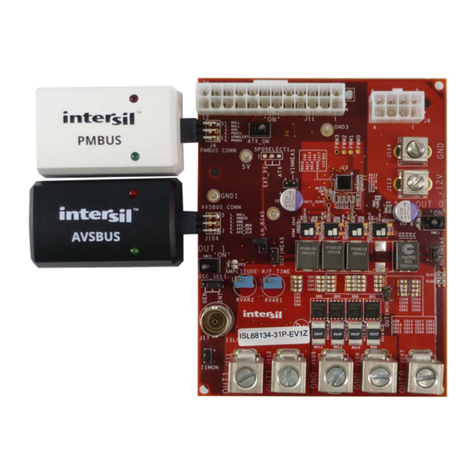
• Connect the ISL28022 board to the dongle as shown in
Figure 6. Enable communication between the evaluation
board and the computer by pressing the “Connect to Device”
button at the bottom right of the software window. If the
connection is successful, the text on the button will be red and
read “Disconnect Device” otherwise, the button text will not
change. Upon successful connection between the PC and the
dongle board, the evaluation software searches specific
resistors to determine the board that is connected to dongle.
• Prior to connecting to the device, a slave address should be
configured to one of 13 available slave addresses on the
Generic ISL28022 Board. Three slave addresses (0x9E, 0x9C
and 0x9A) are reserved to monitor the USB supplies of the
dongle board. The slave address is configured by jumpering
the address pins A0 and A1 to a level. There are four levels
(VCC, GND, SDA and SCL) per pin. The translation between the
jumpered pin value and slave address is defined in the
ISL28022 datasheet.
• Successful connection between the PC and ISL28022
evaluation board will enable the front panel of the Evaluation
Kit GUI while disabling the Demo drop down options.
DATA COLLECTING
• To start collecting data, press the “Start Data Collecting”
button located to the left of the “Connect to Device” button at
the bottom of the screen. Once pressed, the color of the text
and verbiage of the button will change to “Stop Data
Collecting”. The default state of the software reads each DPM
for shunt and bus voltages. To change the read settings of the
DPM, toggle the check box label next to each numerical
readout. The backlight of the display will toggle between
yellow and gray. A backlight of yellow means a channel is
enabled. A change in the functionality of the DPM will change
the mode value for the respective channel. The mode of each
DPM is displayed in the lower left hand corner of each
channel’s display. Figure 6 represents a zoomed in view of a
single DPM interface.
(EQ. 1)
AuxV0.5 1 26100
R7
----------------
+
=
FIGURE 6. DONGLE UNCONNECTED TO THE ISL28022 BOARD
