UG077 Rev 1.00 Page 4 of 30
October 21, 2016
ISL78610EVKIT1Z
Quick Hardware Setup Guide
Single Board
1. Before connecting the power supply to the boards, set the
power supply voltage to 39.6V (3.3V per cell). If there are
fewer cells being tested, reduce the power supply voltage
such that it equals 3.3V times the number of cells.
2. Connect and check the power supply to the MCB_PS3_Z
board. The positive terminal is J5/J11 and the negative
terminal is J8/J12. Check that the voltages on the J2
connector are 3.3V from pin to pin. Ground should be on the
pin labeled “0” and “G”.
If there is no voltage on J2, check that the switches are all set
to “ON”. Also, make sure that there is a jumper on JP2 of the
MCB_PS3_Z board to select the 12-cell option. This puts the
proper voltage on the VBAT pin.
3. Turn off the power to the power supply.
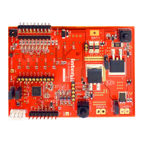
4. Connect ISL78610EVAL2Z connector J4 to the MCB_PS3_Z
board connector J1.
5. Check the jumpers and switches. Since this is a single board
configuration, the ISL78610EVAL2Z board should be
configured as follows:
• EN, LEDEN should contain jumpers.
• EN should be set to ENABLE.
• Place a shunt on the “TOP” jumper for single board
operation.
6. Connect microcontroller board (ISL78MICROEVZ) connector
JP1 to the ISL78610EVAL2Z board connector JP6 (see
Figure 2).
7. Connect the USB port of the PC to the USB port of the
ISL78610EVAL2Z board.
8. Run the GUI. A “Startup” screen in the GUI will indicate
whether the USB dongle is connected and wait for you to
select the evaluation board.
9. Turn on the power to the supply and notice that there are two
green LEDs (V3P3 and xVDD), indicating the LDO regulators
on the ISL78610 are operating.
Once powered, the ISL78610EVAL2Z board voltages at
various points should be:
V3P3 = 3.3V ±3%
VCC = ~3.3V ±5% (a little lower than V3P3)
V2P5 = 2.5V ±2%
VREF = 2.5005V ±0.5mV. (see “Quick GUI Setup Guide (Using
the GUI)” on page 8). Use the software to connect the board
and read the cell voltages.
10. On the GUI, select “Connect”. This will bring up a configuration
box. Select “Non-Daisy” and click on “OK”.
11. Compare the voltages at the board input with the readings
provided by the GUI. Use a meter to measure each of the cell
voltages just after the J3 connector on the ISL78610EVAL2Z
board, because the MCB_PS3_Z board may not accurately
divide the voltages into equal 3.3V steps. Also, measure the
voltage from cell to cell, not cell to ground, to get the best
accuracy. The meter reading and the GUI readout voltages
should closely match (±5.0mV at 3.3V and room
temperature).
Daisy Chain
1. Before connecting the power supply to the boards, set the
power supply voltage to 39.6V (3.3V per cell). If there are
fewer cells being tested, reduce the power supply voltage
such that it equals 3.3V times the number of cells.
2. Connect the power supply to all MCB_PS3_Z boards in
parallel. This is not typical of a battery installation, where the
ground of one board is the VBAT of another, but it easily
facilitates testing of the communication and allows a safer
environment for initial testing.
There should be one MCB_PS3_Z board for every evaluation
board. The positive terminal of the MCB_PS3_Z board is
J5/J11 and the negative terminal is J8/J12. Check that the
voltages on the J3 connectors of all boards are 3.3V from pin
to pin. Ground should be on the pin labeled “0” or “GND”.
3. Turn off the power to the power supply.
4. Connect each ISL78610EVAL2Z board connector J4 to an
MCB_PS3_Z board connector J1.
5. Connect the daisy chain.
The daisy chain can be connected together directly or with
cables, as shown in Figures 3 and 4on page 7 or using a
combination of direct and cable connections. When using
twisted pair cables, connect the wires as shown in Table 1 on
page 5. (Note: the boards are configured to prevent both
direct connection and twisted pair cable connection.)
USE CAUTION when connecting the MCB_PS3_Z boards in
series, since voltages quickly reach hazardous levels. BE
CAREFUL!
