Renkforce WH2600 User manual

- 1 -
IP Observer Internet Weather Station
Operation Manual

- 2 -
1. Introduction
Thank you for your purchase of the IP OBSERVER Internet Weather Station. The following user
guide provides step by step instructions for installation, operation and troubleshooting.
2.Quick Start Guide
Although the manual is comprehensive, much of the information contained may be intuitive. In
addition, the manual does not flow properly because the sections are organized by components.
The following Quick Start Guide provides only the necessary steps to install, operate the weather
station, and upload to the internet, along with references to the pertinent sections.
Required
Step Description Section
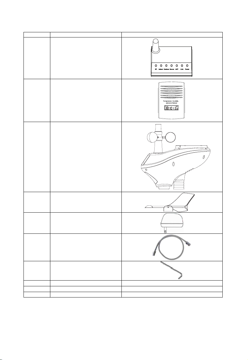
1 Assemble and power up the sensor array -
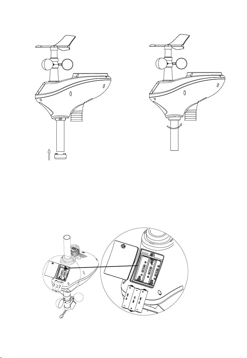
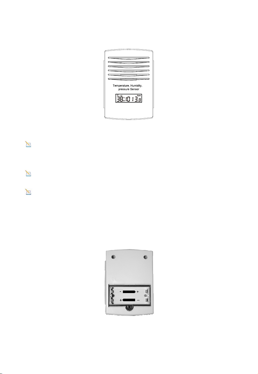
2 Power up the indoor thermometer-hygrometer-barometer
3 Power up the receiver, connect to your router and synchronize with sensor
array and thermo-hygrometer-barometer.
6 Mount the sensor array
5 Calibrate the relative pressure to sea-level conditions (local airport) on console
7 Reset the rain to zero on console
9 Register and upload to Weather Server
3.Pre-Installation Checkout and Site Survey
3.1 Pre Installation Checkout
Before installing your weather station in the permanent location, we recommend operating the
weather station for one week in a temporary location with easy access. This will allow you to check
out all of the functions, insure proper operation, and familiarize you with the weather station and
calibration procedures. This will also allow you to test the wireless range of the weather station.
3.2 Site Survey
Perform a site survey before installing the weather station. Consider the following:
1. You must clean the rain gauge every few months and change the batteries every 2-3 years.
Provide easy access to the weather station.
2. Avoid radiant heat transfer from buildings and structures. In general, install the sensor array
at least 5’ from any building, structure, ground, or roof top.
3. Avoid wind and rain obstructions. The rule of thumb is to install the sensor array at least four
times the distance of the height of the tallest obstruction.
4. Wireless Range. The radio communication between receiver and transmitter in an open field
can reach a distance of up to 100 meter, providing there are no interfering obstacles such as
buildings, trees, vehicles, high voltage lines. Wireless signals will not penetrate metal
buildings.
5. Radio interference such as PCs, radios or TV sets can, in the worst case, entirely cut off
radio communication. Please take this into consideration when choosing receiver or
mounting locations. Make sure your receiver is at least five feet away from any electronic
device to avoid interference.
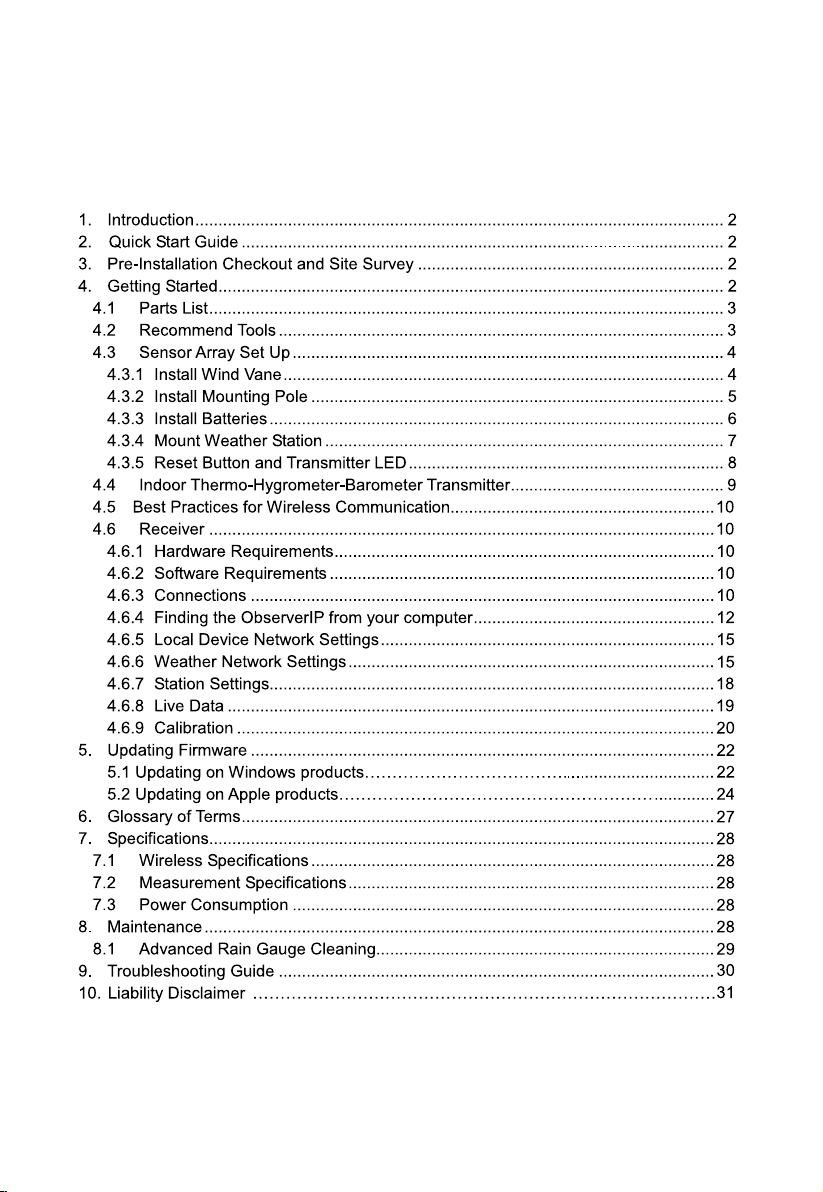
4. Getting Started
The the IP OBSERVER Internet Weather Station consists of a receiver, an all in one sensor array, and
wireless thermo-hygrometer-barometer transmitter.
4.3.1 4.3.3
4.4
4.6
4.3.2
4.6.9
4.6.8.1
4.6.6

- 3 -
4.1 Parts List
QTY Item Image
1 Receiver
1 Thermo-hygrometer-barometer
transmitter
1 Sensor Array
1 Wind Vane
1 5V DC Adaptor
1 Ethernet Cable
1 Allen wrench
1 Pole
1 U-bolt
1 User manual
4.2 Recommend Tools
Precision screwdriver (for small Phillips screw on battery cover door)
Adjustable wrench (for mounting pole)
Compass or GPS (for wind direction calibration)

- 4 -
4.3 Sensor Array Set Up
Figure 1
No Description No Description
1 Wind Vane (measures wind direction) 6 Reset button
2 Wind Speed Sensor (measures wind speed) 7 Thermo-hygrometer Sensor (measures
temperature and humidity)
3 Solar collector 8 UV sensor
4 Battery compartment 9 Solar Radiation Sensor
10 Rain Collector (self emptying) 5 LED transmission indicator (turns on for 10
seconds on power up, flashes once per 16
seconds) 11 Bubble Level
4.3.1 Install Wind Vane
Reference Figure 2. (a) Locate and align the flat key on the wind vane shaft to the flat key on the
wind vane and push the vane on to the shaft. (b) tighten the set screw with the hex wrench
(included).
Figure 2
10
11
1
2
3
4
567
8
9
(a) (b)

- 5 -
4.3.2 Install Mounting Pole
Reference Figure 3. Remove the mounting pole collar by rotating counter clockwise.
Figure 3
Reference Figure 4. Locate and align the groove on the sensor array and mounting pole.
Figure 4

- 6 -
Reference Figure 5. Turn the mounting pole collar to lock the pole into place by rotating clockwise.
Figure 5
4.3.3 Install Batteries
Reference Figure 6. Locate the battery door on the bottom of the sensor array. Turn the set screw
counter clockwise to open the battery compartment. Insert 3xAA batteries (not included).The LED
indicator on the bottom of the sensor array will turn on for ten seconds
and normally flash once per
16 seconds (the transmission update period).
Close the battery door and tighten the set screw.
Figure 6

- 7 -
4.3.4 Mount Weather Station
Fasten the mounting pole to your mounting pole with the U-bolt, mounting pole brackets and nuts,
as shown in Figure 7. Tighten the mounting pole to your mounting pole with the U-Bolt assembly.
Make sure your mounting pole is as far away from the temperature sensor as possible, as shown in
Figure 7.
Figure 7
Reference Figure . Locate the four wind vane compass rose indicators of N, E, S, W
(representing North, East, South and West). Align the compass rose direction upon final
installation with a compass or GPS.
Figure 8
Note:Please use good quality alkaline batteries. The batteries are intended for back-up power only.
The solar cell current charges the supercapacitor.

- 8 -
Reference Figure 9. Make sure the sensor array is completely level upon final installation.
Failure to do so will result in inaccurate rain gauge readings.
Figure
4.3.5 Reset Button and Transmitter LED
In the event the sensor array is not transmitting, reset the sensor array.
With an open ended paperclip, press and hold the RESET BUTTON for three seconds to completely
discharge the voltage.
Take out the batteries and wait one minute, while covering the solar panel to drain the voltage.
Put batteries back in and resynchronize with the receiver by powering down and up the receiver with the
sensor array about 3meter away.
Figure
LED RESET BUTTON
LED RESET BUTTON
9
10

- 9 -
4.4 Indoor Thermo-Hygrometer-Barometer Transmitter
The indoor thermometer, hygrometer and barometer measures and displays the indoor temperature,
humidity and pressure and transmits this data to the receiver.
Figure 11
Note: Do not install the thermo-hygrometer-barometer transmitter outside. This will cause errors in
the barometric pressure due to large variations in temperature (barometric pressure is temperature
compensated for accuracy). Note that pressure readings made inside your home, business, or facility
will correspond closely to the actual barometric pressure outside.
Note: The thermo-hygrometer-transmitter transmits directly to the receiver. For best results, place
between 2 to 8 meter from the receiver.
Note: To avoid permanent damage, please take note of the battery polarity before inserting the
batteries.
Remove the battery door on the back of the sensor with a Philips screwdriver (there is only one screw, at
the bottom of the unit). Insert two AAA batteries, as shown in Figure 12.
Replace the battery door and set screw. Note that the temperature, humidity and barometric pressure
will be displayed on the LCD display. Looking at the back of the unit from left to right, the polarity is (-) (+)
for the top battery and (+) (-) for the bottom battery.
Figure 12

- 10 -
4.5 Best Practices for Wireless Communication
Note: To insure proper communication, mount the remote sensor(s) upright on a vertical surface,
such as a wall. Do not lay the sensor flat.
Wireless communication is susceptible to interference, distance, walls and metal barriers. We
recommend the following best practices for trouble free wireless communication.
1. Electro-Magnetic Interference (EMI). Keep the receiver one meter away from computer
monitors and TVs.
2. Radio Frequency Interference (RFI). If you have other 433 MHz devices and communication is
intermittent, try turning off these other devices for troubleshooting purposes. You may need to
relocate the transmitters or receivers to avoid intermittent communication.
3. Line of Sight Rating. This device is rated at 100meter line of sight (no interference, barriers or
walls) but typically you will get 30meter maximum under most real-world installations, which
include passing through barriers or walls.
4. Metal Barriers. Radio frequency will not pass through metal barriers such as aluminum siding. If
you have metal siding, align the remote and receiver through a window to get a clear line of sight.
The following is a table of reception loss vs. the transmission medium. Each “wall” or obstruction
decreases the transmission range by the factor shown below.
Medium RF Signal Strength Reduction
Glass (untreated) 5-15%
Plastics 10-15%
Wood 10-40%
Brick 10-40%
Concrete 40-80%
Metal 90-100%
4.6 Receiver
4.6.1 Hardware Requirements
1. Broadband router
2. An “always-on” connection to the Internet. A high speed DSL or cable internet connection
that maintains constant connection to the internet.
4.6.2 Software Requirements
An IP scan tool (included) is required to locate the device on the network.
4.6.3 Connections
Connect the receiver power jack to AC power with the power adapter (included), as shown in
Figure 1
Connect the receiver to your router using the Ethernet cable (included), as shown in
Figure 1ence 8.
Place the sensor array and indoor thermo-hygrometer transmitter about 1 to 3meter from the
receiver and wait several minutes for the remote sensors to synchronize with the receiver. Once
synchronized, the Indoor blue LED ( , reference 2) and Outdoor blue LED (
reference 3) will be illuminated.
4, reference 10.
4, refer
Figure 13Figure 13,

- 11 -
Figure 13
Ref. LED Description
1 RF On when radio frequency receiver is operating properly
2 Indoor On when indoor sensor received
3 Outdoor On when outdoor sensor array received
4 Server On when connected to Wunderground.com® internet hosting
service
5 ACT Flashes when there is internet activity
6 Link Connected to the Internet (or router)
7 Power AC Power connected
Ref. Description
8 LAN connection (connect to router)
9 Reset button
10 AC Power connection
Figure 14

- 12 -
4.6.4 Finding the ObserverIP from your computer
4.6.4.1 Windows PC Users
To find the ObserverIP receiver, launch the IP Tools software. The HostIP (your computers IP
address) will be displayed. Press the OK button to continue.
Figure 1
Select the Search button to find the device on your local area network.
Figure 1
Select the device on your network and select the Open button to view within your browser.
Alternately, you can type the IP address in your web browser address bar (example, Figure 17):
Figure 1
Figure 1
5
6
7
8

- 13 -
You are now communicating directly to the device and can proceed to Section 4
If you cannot access the device, press the reset pinhole on the back of the receiver (reference
Figure 13) and wait for the lights to stabilize, and repeat by selecting the Search button again.
4.6.4.2 Mac PC Users
Launch the IP tool. The HostIP (your computers IP address) will be displayed.
Figure 19
Click the Search button (Figure 20) to find the device on your local area network (Figure 21).
Figure 20
Figure 21
.6.5.

- 14 -
Select the device on your network and click the Open button(Figure 22) to view within your browser.
Alternately, you can type the IP address in your web browser address bar.(example, Figure 23)
Figure 22
Figure 23
4.6.4.3 Linux Users
If you use Linux operating system, download any commercially available IP scan tool, such as
AngryIP Scanner and find the MAC address of the device. The MAC address is a unique identifier
for internet enabled devices.
The MAC address will be printed on the bottom of the ObseverIP receiver. An example MAC
address is 00:0E:C6:00:00:19.
Figure 24 shows typical scan results. Locate the IP address of the device by cross referencing the
Mac address. In the example below, the IP address is 192.168.0.105.
Figure 24
Type the IP address you located from the IP Scan Tool into your web browser (example, Figure ):
Figure 25
You are now communicating directly to the device and can proceed to Section 0.
25

- 15 -
4.6.5 Local Device Network Settings
From your web browser, access the device from the IP address obtained in the previous section.
Select the Local Network tab to program the local network settings. Reference Figure
1. IP Address. The default setting is receive automatically (DCHP), which is recommended.
The network will assign an IP address. To statically assign an IP address, select Static from
the pull down menu. This will prevent the IP address from changing each time you power up
the receiver.
2. Static IP Address. If Static is selected as the IP address, enter the IP address you wish to
access the device.
3. Static Subnet Mask. Default is 255.255.255.0. This should not be changed unless you are
familiar with networking and subnet masking.
4. Static Default Gateway. This is typically the IP address of your router.
5. Static DNS Server. This is your DNS Server setting based on your router connection.
6. Server Listening Port. Default is 5000. Enter an integer between 1024 – 65535.
To confirm the changes, select Apply and Reboot.
Note: If you incorrectly set the static IP settings and can no longer access the device, press the
reset button on the back of the receiver.
Figure
4.6.6 Weather Network Settings
Select the Weather Network tab to program the Weather Network settings. Reference Figure 27:
1. Remote Server. The default setting is rtupdate.wunderground.com, which is recommended. If
you want to upload the weather data to your own website, select Customized from the pull
down menu
2. Server IP/Hostname. If Customized is selected as remote server, enter the host name or IP
address.
3. Server Port. Default is 80. Enter an integer between 1024~65535
4. Server type. Default is PSP. (JSP, PHP, ASP)
5. Station ID.
6. Password.
To confirm the changes, select Apply.
26:
26

- 16 -
Figure 27
If you select default remote server as rtupdate.wunderground.com, please follow the below
procedure to got the Weather ID and Pass word.
1. Join the Wunderground.com® Community. Visit:
https://www.wunderground.com/members/signup.asp
and sign up with Wunderground.com.
2. Join the Personal Weather Station (PWS) network. Visit:
http://www.wunderground.com/personal-weather-station/signup
or select More | Register Your PWS from the menu at the top of the
WeatherUndeground.com website:

- 17 -
Enter the Station ID obtained and password you sign up with Wunderground.com.
Note: If Wunderground.com® is not updating, make sure the Station ID and Password are
correct. The Station ID is all capital letters, and the password is case sensitive. The most common
issue is substituting an O for 0 in the Station ID. Example, You live in Phoenix, AZ and you are
station number 11:

- 18 -
Station ID:
KAZPHOEN11, not KAZPH0EN11
K = USA station designation
AZ = Arizona
PHOEN = Phoenix
11= station 11 in Phoenix, AZ
4.6.7 Station Settings
Select Apply to confirm any of the changes in this section.
4.6.7.1 Wireless Transmitter Settings
1. Indoor Sensor Type: Enter WH25 for the indoor thermometer-hygrometer-barometer
(default).
2. Outdoor Sensor1 Type: Enter WH24 for the outdoor sensor array (default).
3. Outdoor Sensor2 Type: Enter none. At the present time, additional sensors are not
available.
4.6.7.2 Time Zone Setting
Enter your local time zone and daylight Savings Time.
4.6.7.3 Daylight Savings Time
There are three options to select from:
1. Off-If it is not Daylight Saving Time for your location.
2. On-If it is Daylight Saving Time for your location(you will need to switch this off when your
location returns to Standard Time)
3. Auto-Your station will automatically turn Daylight Saving Time on and off based on German
(868 MHz and 433 MHz version) or US (915 MHz version) Daylight Saving Time.
4.6.7.4 Units of Measure
Enter your preferred units of measure for each parameter.
Figure 28

- 19 -
4.6.8 Live Data
Select the Live Data tab to view your live data from the weather station. To freeze the live data updates,
select the Stop Refresh button.
4.6.8.1 Reset Rain
During the installation of your weather station, you may report false rain due to vibration of the tipping
mechanism. To reset the rain to 0.00, select the Rain Reset button as shown in Figure 29.
Figure 29

- 20 -
4.6.9 Calibration
Select the Calibration tab to view your calibration data from the weather station. Select the Apply button
to confirm changes.
Calibration of most parameters is not required, with the exception of Relative Pressure, which must be
calibrated to sea-level to account for altitude effects. For more information on sea-level pressure
calibration, please reference note (3) below.
4.6.9.1 Relative Barometric Pressure Calibration Example
The following is an example of calibrating the relative pressure. Your results will vary.
1. The local relative pressure from TV, the newspaper or the internet for the official station in
your area is 30.12 inHg.
2. From the Live Data panel, your absolute pressure (measured, and not corrected to sea-level)
reads 30.47 inHg.
3. Reference
Figure . Enter the following offset in the Calibration panel for Relative Pressure
Relative Pressure Offset = 30.12 – 30.47 = -
Figure 30
Offset:
30
0.35
Table of contents
Other Renkforce Weather Station manuals

Renkforce
Renkforce 1267653 User manual

Renkforce
Renkforce 1267774 User manual

Renkforce
Renkforce WH2315 User manual

Renkforce
Renkforce 1208067 User manual

Renkforce
Renkforce 2203406 User manual

Renkforce
Renkforce E0303H2TR User manual

Renkforce
Renkforce FT0100 User manual

Renkforce
Renkforce 1414020 User manual

Renkforce
Renkforce 1267659 User manual

Renkforce
Renkforce 2377869 User manual