Renogy Smart Shunt 300 User manual

USER MANUAL
VERSION A0
Smart Shunt 300
RENOGY
RSHST-B02P300-G1
B1
B2
T1

Before Getting Started
The user manual provides important operation and maintenance instructions for Renogy Smart Shunt
300 (hereinafter referred to as shunt).
Read the user manual carefully before operation and save it for future reference. Failure to observe the
instructions or precautions in the user manual can result in electrical shock, serious injury, or death, or
can damage the Renogy Smart Shunt, potentially rendering it inoperable.
zRenogy ensures the accuracy, sufficiency, and the applicability of information in the user manual
at the time of printing due to continual product improvements that may occur.
zRenogy assumes no responsibility or liability for personal and property losses, whether directly and
indirectly, caused by the user’s failure to install and use the product in compliance with the user
manual.
zRenogy is not responsible or liable for failures, damages, or injuries resulting from repair attempted
by unqualified personnel, improper installation and operation.
zThe illustrations in the user manual are for demonstration purposes only. Details may appear
slightly different depending on product revision and market region.
zRenogy reserves the right to change the information in the user manual without notice. For the
latest user manual, visit renogy.com.
Disclaimer
Renogy Smart Shunt 300 User Manual © 2023 Renogy. All rights reserved.
RENOGY and are registered trademarks of Renogy.
zAll information in the user manual is subject to copyright and other intellectual property rights of
Renogy and its licensors. The user manual may not be modified, reproduced, or copied, in whole or
in part, without the prior written permissions of Renogy and its licensors.
zThe registered trademarks in the user manual are the property of Renogy. The unauthorized use of
the trademarks is strictly prohibited.
Online Manual
Quick Guide User Manual
DC Home App
DC Home App

1. General Information ........................................................................................................................... 1
1.1. Symbols Used .............................................................................................................................................. 1
1.2. Introduction ................................................................................................................................................. 1
1.3. Key Features ................................................................................................................................................ 1
1.4. SKU................................................................................................................................................................. 1
2. Get to Know Renogy Smart Shunt 300.............................................................................................2
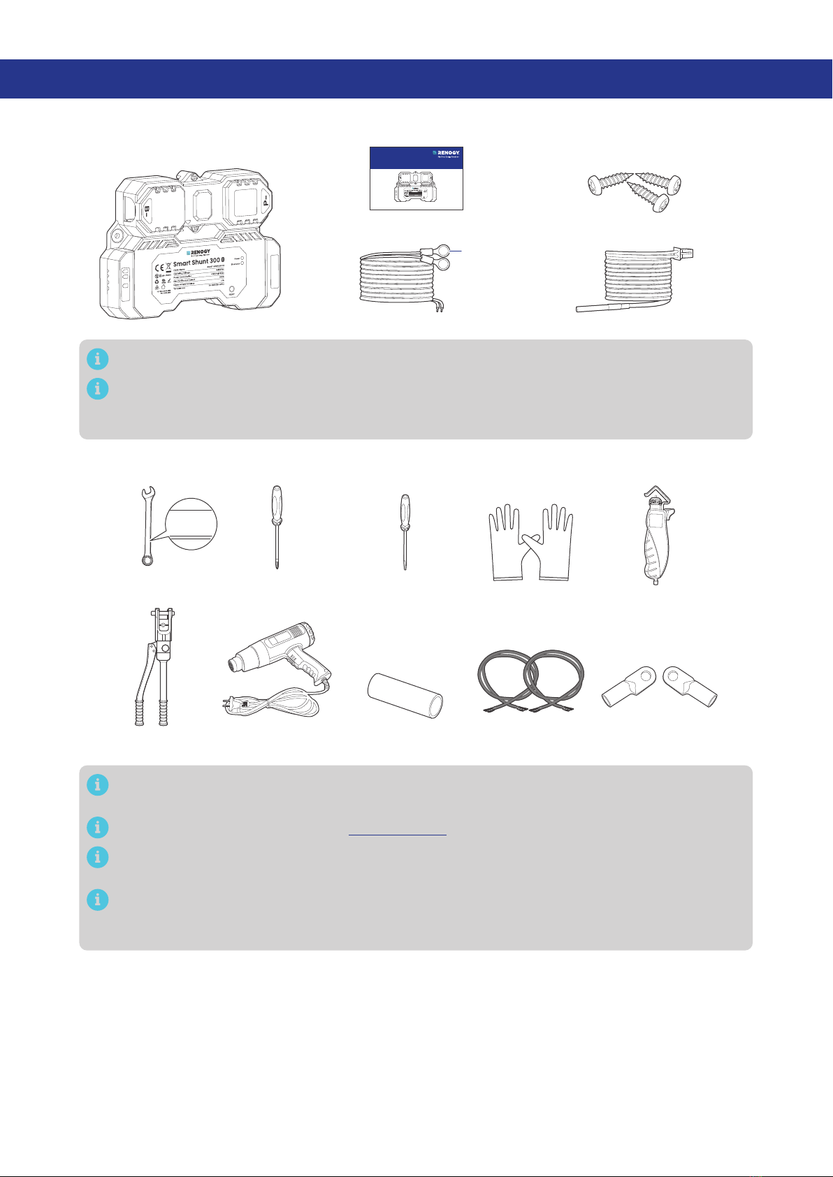
2.1. What’s In the Box? ..................................................................................................................................... 2
2.2. Required Tools & Accessories.................................................................................................................. 2
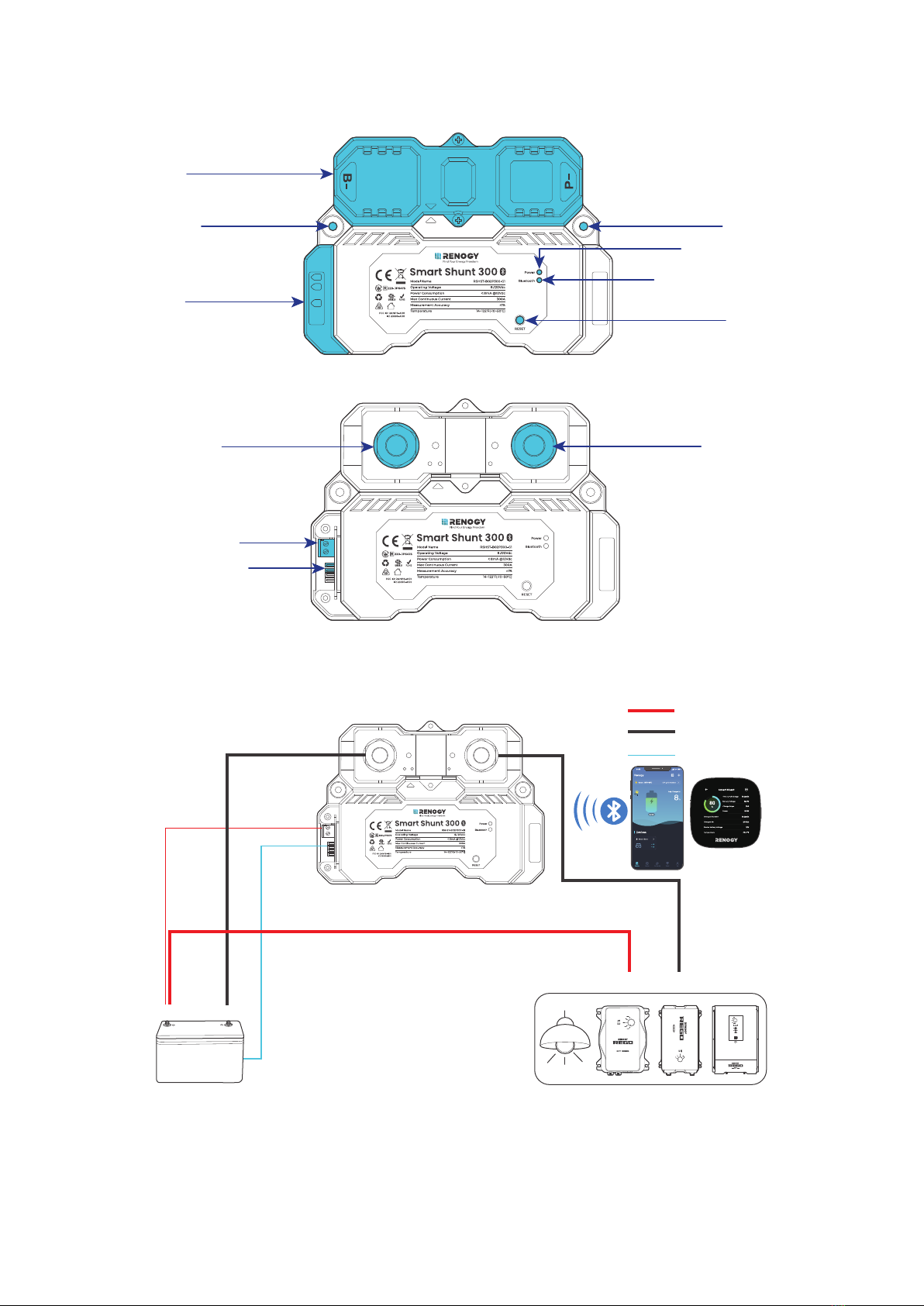
2.3. Product Overview....................................................................................................................................... 3
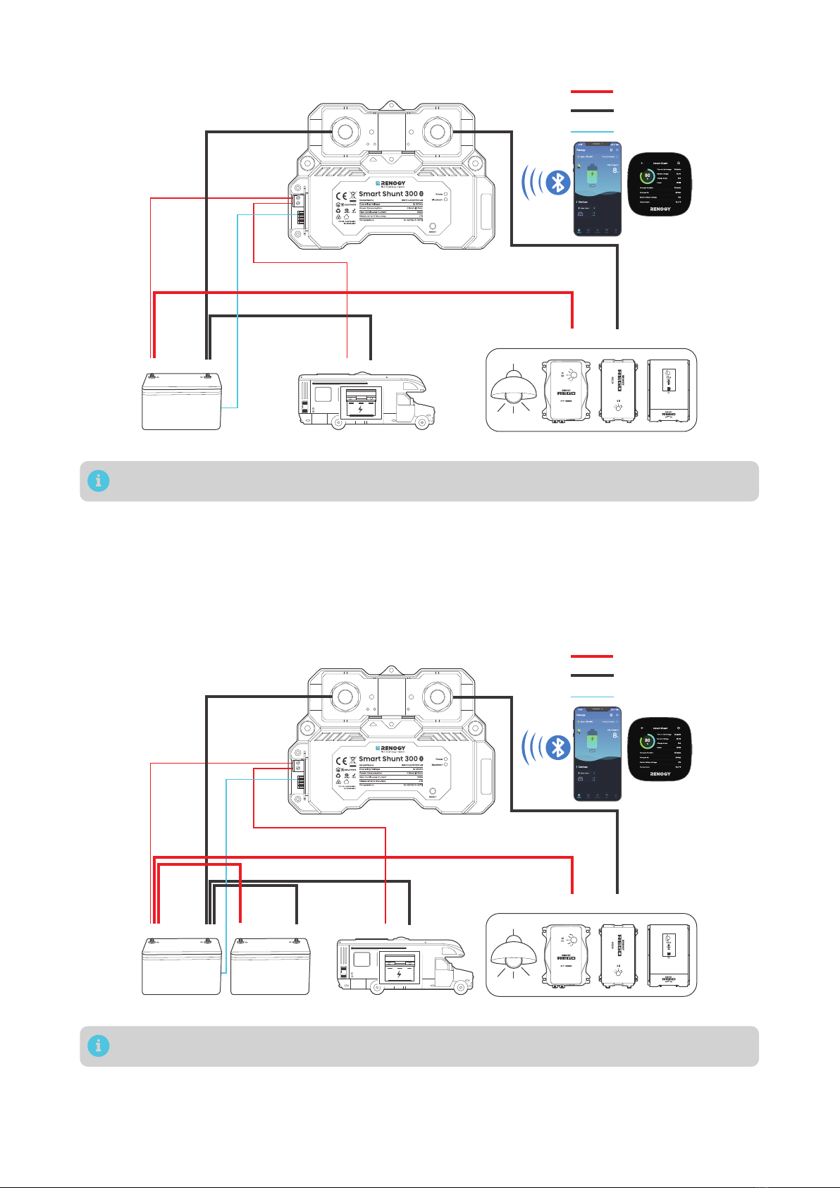
2.4. System Setup ............................................................................................................................................. 3
3. Preparation .........................................................................................................................................6
3.1. Plan a Mounting Site ................................................................................................................................. 6
3.2. Check Renogy Smart Shunt 300 ............................................................................................................ 6
3.3. Check System Voltage and Current........................................................................................................7
3.4. Size Bare Wires ............................................................................................................................................7
3.5. How to Install 3/8 in Lugs? .......................................................................................................................7
4. Installation ..........................................................................................................................................9
4.2. Remove the Covers.................................................................................................................................... 9
4.3. Connect the Shunt to the Main Battery Negative..............................................................................10
4.4. Connect the Shunt to the Device BAT- ................................................................................................10
4.5. Connect the Shunt to the Main Battery Positive................................................................................ 11
4.6. Install a Battery Temperature Sensor................................................................................................... 11
4.7. Connect the Shunt to the Starter Battery Positive (Optional) ........................................................12
4.8. Mount the Shunt (Optional) ....................................................................................................................12
4.9. Install the Covers ......................................................................................................................................13
5. Configuration.................................................................................................................................... 14
5.1. Power On.....................................................................................................................................................14
5.2. Pairing with DC Home or Renogy ONE..................................................................................................14
5.3. Energy Monitoring.....................................................................................................................................16
5.4 SOC Synchronization ...............................................................................................................................18
6. LED Indicators................................................................................................................................... 21
7. Troubleshooting................................................................................................................................22
8. FAQ......................................................................................................................................................23
9. Dimensions and Specifications.......................................................................................................24
9.1. Dimensions................................................................................................................................................ 24
9.2. Technical Specifications......................................................................................................................... 24
Table of Contents

Maintenance..............................................................................................................................................26
Inspection .............................................................................................................................................................26
Cleaning ................................................................................................................................................................26
Storage.................................................................................................................................................................. 26
Emergency Responses.............................................................................................................................27
Renogy Support ........................................................................................................................................28
FCC & RSS ..................................................................................................................................................29
FCC Statement .................................................................................................................................................... 29
FCC Radiation Exposure Statement................................................................................................................ 29
RSS Standard....................................................................................................................................................... 29

— 1 —
1. General Information
1.1. Symbols Used
The following symbols are used throughout the user manual to highlight important information.
WARNING: Indicates a potentially dangerous condition which could result in injury or death.
CAUTION: Indicates a critical procedure for safe and proper installation and operation.
NOTE: Indicates an important step or tip for optimal performance.
1.2. Introduction
Renogy Smart Shunt 300 is an intelligent battery monitor that measures the battery voltage and current
based on which it calculates the state of charge (SOC) and remaining running time of the battery.
In addition, the shunt records historical charging and discharging data such as full deep discharge
cycle, discharge capacity, charge cycle, and battery temperature.
With the built-in Bluetooth module, Smart Shunt 300 communicates with the DC Home app and
Renogy ONE. This allows you to monitor real-time charging and discharging data and customize related
parameters. These settings encompass nominal capacity, deep discharge thresholds, temperature
alarms, and SOC alarms.
1.3. Key Features
zUniversal Battery Compatibility
Works seamlessly with various battery types, including Lead Acid (AGM, GEL), Lithium Iron Phosphate,
Lithium-ion, and Nickel-metal hybrid.
zComprehensive Battery Insights
Provides vital battery information such as State of Charge (SOC), voltage, current, energy, remaining
time, temperature, and starter battery voltage.
zAlarm and Historical Data
Records historical data and offers alerts for abnormal conditions through the DC Home app.
zConvenient Remote Monitoring
Enables remote monitoring and control via Renogy ONE and the DC Home App using Bluetooth
connectivity.
zEffortless Installation and Configuration
Simplifies installation and settings adjustments through the DC Home app for a user-friendly
experience.
1.4. SKU
Renogy Smart Shunt 300 RSHST-B02P300-G1

— 2 —
2. Get to Know Renogy Smart Shunt 300
2.1. What’s In the Box?
Renogy Smart Shunt 300 × 1
Quick Guide × 1
B1/B2 Wires (1 m) (22 AWG) × 2 Temperature Sensor (1.5 m) × 1
VERSION A0
Smart Shunt 300
RENOGY
RSHST-B02P300-G1
QUICK GUIDE
Mounting Screws x 3
(1 extra)
ST4 x 18 mm
3/8 in
(M10)
B1
B2
T1
B1
B2
T1
Make sure that all accessories are complete and free of any signs of damage.
The accessories and product manual listed are crucial for the installation, excluding warranty
information and any additional items. Please note that the package contents may vary
depending on the specific product model.
2.2. Required Tools & Accessories
Insulating Gloves
Bare Wires × 2
Wrench
(11/16 in)
17 mm
17 mm
17 mm
Phillips
Screwdriver (#1) Wire stripper
Slotted
Screwdriver (1 mm)
Manual Hydraulic
Pliers
3/8 in Lugs
(M10 Ring Terminals) × 2
Heat Gun Heat Shrink Tubing
Prior to installing and configuring the shunt, prepare the recommended tools, components, and
accessories.
For how to size bare wires, refer to “Size Bare Wires” in this manual.
For how to install 3/8 in Lugs (M10 Ring Terminals), see “How to Install 3/8 in Lugs?“ in this
manual.
For connection methods and required tools for the auxiliary battery, starter battery, and
equipment terminal, please refer to the user manual of the specific device. The diagrams
provided within this manual are for illustrative purposes only.

— 3 —
2.3. Product Overview
█Exterior
Upper Cover
Lower Cover
Mounting Hole Mounting Hole
Power LED Indicator
Bluetooth LED Indicator
RESET Button
B1
B2
T1
█Interior (with the covers removed)
B- Terminal (M10)
B1 and B2 Terminals
Battery Temperature
Sensor (T1) Port
P- Terminal (M10)
2.4. System Setup
█Connecting to a Main Battery Only
Main Battery
Positive
+
-
Temperature
B-
B1
P- Negative
Loads / Chargers / Inverters
BAT-BAT+
DC-DC Battery Charger
-
+
T1

— 4 —
█Connecting to Both a Main Battery and a Starter Battery
Main Battery
Positive
+
- -
+
Temperature
B-
B1
P- Negative
Starter Battery
Loads / Chargers / Inverters
BAT-BAT+
DC-DC Battery Charger
-
+
B2
T1
In such scenario, the shunt detects voltage of both the main battery and the starter battery.
█Connecting to Multiple Main Batteries
The illustrations depict two batteries in parallel as an example. There is no limit on the number of
batteries in parallel. You can customize the setup with more batteries as needed.
Please ensure the combined continuous current from the batteries must not surpass 300A, maintaining
a voltage below 120V.
Main batteries in parallel
Main Batteries
Positive
+
- -
+
Temperature
B-
B1
P- Negative
Starter Battery (optional)
Loads / Chargers / Inverters
BAT-BAT+
DC-DC Battery Charger
-
+
+
-
-
+
B2
T1
You can connect the Smart Shunt 300 to a starter battery via the B2 port on demand.

— 5 —
The illustrations depict two batteries in series as an example. There is no limit on the number of
batteries in series. You can customize the setup with more batteries as needed.
Please ensure the continuous current from the batteries must not surpass 300A, maintaining a total
voltage below 120V.
Main batteries in series
Main Batteries
Positive
+
- -
+
Temperature
B-
B1
P- Negative
Starter Battery (optional)
Loads / Chargers / Inverters
BAT-BAT+
DC-DC Battery Charger
-
+
+
-
-
+
B2
T1
You can connect the Smart Shunt 300 to a starter battery via the B2 port on demand.

— 6 —
3. Preparation
3.1. Plan a Mounting Site
Select a proper mounting site to ensure the shunt can be safely connected to the battery and other
necessary devices with the relevant cables. Install the shunt in a clean, cool, and dry location, free from
any accumulation of water, oil, or dirt. For optimal Bluetooth communication, avoid placing the smart
shunt near metal objects.
KEEP DRY FRAGILE VENTILATION
14°F to 122°F
-10°C to 50°C 0% to 95%
Enclosed space
Vent
Vent
Air
cross-flow
B1
B2
T1
Install the Renogy Smart Shunt 300 indoors and prevent its components from being exposed to
direct sunlight.
Do not expose Renogy Smart Shunt 300 to flammable or harsh chemicals or vapors.
Keep Renogy Smart Shunt 300 out of the reach of children.
Make sure that the Renogy Smart Shunt 300 is installed with ambient temperature range from
-4°F to 122°F or -20°C to 50°C.
Make sure that the Renogy Smart Shunt 300 is installed in an environment with relative humidity
between 0% and 95% and no condensation.
3.2. Check Renogy Smart Shunt 300
B1
B2
T1
Inspect the shunt for any visible damage including cracks, dents,
deformation, and other visible abnormalities. All connector contacts
shall be clean, dry, and free of dirt and corrosion.
Do not use Renogy Smart Shunt 300 if it appears to be damaged.
There are no serviceable parts in Renogy Smart Shunt 300. Do not open, dismantle, repair,
tamper with, or modify it.
Wear proper protective equipment and use insulated tools during installation.
Do not dispose of Renogy Smart Shunt 300 as household waste. Comply with local, state, and
federal laws and regulations and use recycling channels as required.

— 7 —
3.3. Check System Voltage and Current
8V to 120V
-
+
Ensure the smart shunt operates within a power system with a
maximum system voltage of 120V and a continuous current of up
to 300A. Exceeding these voltage and current limits may cause
damage to the shunt.
Risk of electric shock! Before installing the shunt, please turn off all devices within the system
and ensure there is no current flowing through the circuit.
3.4.Size Bare Wires
Select proper bare wires based on the ampacity in your power system. Refer to the table below for
copper cable ampacities with different gauge sizes.
Cable Gauge Size Ampacity Cable Gauge Size Ampacity
14 AWG (2.08 mm²) 35A 2 AWG (33.6 mm²) 190A
12 AWG (3.31 mm²) 40A 1 AWG (42.4 mm²) 220A
10 AWG (5.25 mm²) 55A 1/0 AWG (53.5 mm²) 260A
8 AWG (8.36 mm²) 80A 2/0 AWG (67.4 mm²) 300A
6 AWG (13.3 mm²) 105A 4/0 AWG (107 mm²) 405A
4 AWG (21.1 mm²) 140A
The above values are from the NEC Table 310.17 for copper cables rated at 194°F (90°C), operating
at an ambient temperature of no more than 86°F (30°C). Cables longer than 13 feet (4000 mm)
may require thicker gauge wires to prevent excessive voltage drop in undersized wiring.
3.5. How to Install 3/8 in Lugs?
0.4 in
(10 mm)
Bare
Wire
Step 1: Strip approximately 0.4 inches (10 mm) of insulation from
the end of a bare wire using a wire stripper.

— 8 —
Heat
Shrink
Tubing
Step 2: Thread the exposed bare wire through a piece of heat shrink
tubing.
Step 3: Attach a 3/8-inch lug onto the end of the bare wire.
Step 4: Securely crimp the lug
onto the bare wire using a manual
hydraulic pliers.
Step 5: Slide the heat shrink tubing over the 3/8-inch lug.
Step 6: Apply heat to the heat shrink
tubing using a heat gun until it
shrinks and forms a tight seal.

— 9 —
4. Installation
To ensure safe and efficient operation of the inverter charger and to avoid potential damage or hazards,
always follow the installation instructions in the sequence described in this manual.
4.1. Wear Insulating Gloves
Insulating Gloves
B1
B2
T1
4.2. Remove the Covers
█Remove the Upper Cover
B1
B2
T1
B1
B2
T1
█Remove the Lower Cover
B1
B2
T1
B1
B2
T1

— 10 —
4.3. Connect the Shunt to the Main Battery Negative
173.5—224.8 in·lbs
(19.6—25.4 N·m)
-
-
+
Main Battery
STEP-1 Install the bare wire on the shunt B- terminal.
STEP-2 Install the bare wire on the battery negative.
Renogy Smart Shunt 300
Bare Wire
1 2
-
B-
B-
4.4. Connect the Shunt to the Device BAT-
DC-DC Battery Charger
Loads & Charges & Inverters
BAT-
BAT-
DC-DC Battery Charger
STEP-1 Install the bare wire on the shunt P- terminal.
STEP-2 Install the bare wire on the device BAT-.
Renogy Smart Shunt 300
Bare Wire
12
P- P-
173.5—224.8 in·lbs
(19.6—25.4 N·m)

— 11 —
4.5. Connect the Shunt to the Main Battery Positive
+
+
-
+
Main Battery
STEP-1 Install the B+ wire on the shunt B1 terminal.
STEP-2 Install the B+ wire on the main battery positive.
Renogy Smart Shunt 300
B1 Wire
1 2
Open Close
B1
4.6. Install a Battery Temperature Sensor
Temperature Sensor
Battery Temperature
Sensor Port

— 12 —
4.7. Connect the Shunt to the Starter Battery Positive (Optional)
+
+
Starter Battery
STEP-1 Install the B+ wire on the shunt B2 terminal.
STEP-2 Install the B+ wire on the starter battery positive.
Renogy Smart Shunt 300
B2 Wire
12
Open Close
B2
4.8. Mount the Shunt (Optional)
To guarantee system safety, mounting the shunt to a proper location is recommended. You can choose
a proper mounting site on demand.

— 13 —
4.9. Install the Covers
█Install the Lower Cover
B1
B2
T1
B1
B2
T1
█Install the Upper Cover (Optional)
B1
B2
T1
Installing the Upper Cover is optional in cases where the terminals are not enclosed by the cover.

— 14 —
5. Configuration
5.1. Power On
Power on all devices in your power system, and the Smart Shunt is
powered up automatically with the Power LED Indicator lighting up.
5.2. Pairing with DC Home or Renogy ONE
For initial use, set the “Rated Battery Ah” (rated battery capacity) on the app prior to other operations.
Rated Battery Ah should be the same as the rated capacity of the specific battery you use. For details,
refer to the battery user manual.
█Initial Paring
For initial startup, follow the steps below to pair the shunt with the DC Home app or Renogy ONE.
Step 1: On DC Home or Renogy ONE,
navigate to “Add Devices”.
Step 2: Scan and pair the shunt with
the Renogy ONE or DC Home app.

— 15 —
█Pairing with Another Device
5s
Step 1: Remove the shunt from the
DC Home app or ONE. Alternatively,
you can press and hold RESET on the
shunt for 5s.
Step 2: After the Bluetooth LED turns
off, redo scanning and pairing.

— 16 —
5.3. Energy Monitoring
Depending on the specific application, the shunt can establish either short-range or long-range
communication connections with monitoring devices. These monitoring devices including RENOGY ONE
Core and DC Home facilitate real-time monitoring, programming, and complete system management,
offering comprehensive control and enhanced flexibility.
The version of the DC Home app might have been updated. Illustrations in the user manual are for
reference only. Follow the instructions based on the current app version.
Download and login to the DC Home app.
DC Home App
█Short-Range Monitoring via DC Home App
2 3 4
1
On after
successful
pairing
B1
B2
T1
Other manuals for Smart Shunt 300
1
This manual suits for next models
1
Table of contents
Other Renogy Batteries Pack manuals