manuals.online logo
Brands
  1. Home
  2. •
  3. Brands
  4. •
  5. Renogy
  6. •
  7. Inverter
  8. •
  9. Renogy PWM30CC-LCD User manual

Renogy PWM30CC-LCD User manual

!!!! !
30A PWM Solar Charge Controller with LCD
Model: PWM30CC-LCD
1. Product Introduction
This controller is an intelligent and multifunctional solar charge controller. These
serial products adopt customized LCD display screens, which make operations
on the interface rather convenient. All of the controlling parameters can be reset
to satisfy user needs. This controller has the following features:
•Visual LCD graphic symbol
•Brief key operation
•Grade auto-switch of system voltage
•Intelligent PWM Charging Mode
•Auto temperature compensation
•Adjustable charging & discharging parameter
•Settable working modes of loads
•Accumulative function of charging &
discharging AH
•Protection for battery back discharging
•Protection for battery low voltage
•Overloading & short-circuit protection
•Battery reversed protection
•Delayed auto restart after overloading
protection
2. Installation Explanation
Prepare the related tools and cables. Renogy suggests you choose the
appropriate cables to ensure the current density < 4 A/mm2, which is good for
reducing cable voltage drop. Recommendation: 30A using AWG 8 cable, or 50A
using AWG 6 cable.
1. Check whether the place of installation accords with the relative safety
rules. Please avoid installing and using the controller under the following
conditions: wet places, dusty places, or places with flammable and
explosive gases.
2. Install the controller at the vertical plane. Please refer to chapter 5 for
more detailed information about the required spacing between installing
holes. In order for the controller to have good thermal dissipation, please
spare 10cm above and below the controller.
!
1
3. As shown in the figure to the right, connect the loads, battery, and solar
panels with the controller in proper order. Pay close attention when
connecting the loads, battery, and solar panels, to ensure the job is done
correctly.
4. Plug the external thermal sensor into the interface of the thermal sensor
on the left side of the controller.
!
Disassemble: To avoid a dangerous accident, please dismantle the solar
panels, battery, and loads from the controller in the proper order.
Attention: Connecting the battery in a reversed manner will not damage the
controller, but will create a safety risk on your loads
3. Operation
Explanation of LCD Graphic Symbols
Symbol
Description
Stop supplying power for loads
Supplying power for loads, no current in load loop
Current in load loop
Load icon
Solar panels icon
Solar Panels
Battery
DC Load
Temperature Sensor
Interface
Controller
!
2
Load light control
Load timing control
Stop charge for battery
Charging battery at full speed
Float charging
Normal working state
Abnormal working state
Battery capacity display
Battery icon
TABLE 3.1 LCD graphic symbols description
Explanation of Buttons
!
!
Interfaces circular toggling button: Use of this button can realize
(show/create) the toggling circularly among the interfaces. The
circular order is properly shown in figure 1.
!
Parameter adjusting'+'+ button. Besides, under parameter review
condition, press this button for over 5 seconds, and all the parameters
will recover to the ex-work setting state.
!
Parameter adjusting'-'button. Besides, at the main interface, this
button can turn on or turn off the load.
!
!
!
!
Battery Voltage
(Main interface)
Battery
Temperature
Solar Panels
Input Current
Load Current
Accumulative
Generated Ah
Load Working
State
Ceasing Charging
Voltage
Recovery
Voltage
Low Voltage
Protection Point
Accumulative,
Used Ah
!
3
Parameter Review and Setting
After the controller properly electrifies, it will enter the battery voltage onto the
displaying interface. This interface is the main interface of the controller. Press
button to go through the interfaces of the following parameters. If the interface
can be reset, press button for at least 5 seconds (>5 seconds, and the
number on the interface starts to flicker), then it will enter into the setting
interface of this parameter. After finishing the setting, press button for over 5
seconds to exit the setting interface, and the number will cease flickering.
3.1 Battery Voltage Review
As shown in the figure to the right, the displayed
number is the present battery voltage. This
interface is the main interface, and it shows the
charging and discharging state, battery capacity,
and battery voltage.
3.2 Load ON/OFF Controlling
At the battery voltage review interface, you can
press button to turn the load on or off;
however, this button does not have the same
function at other interfaces.
3.3 Environmental Temperature Review
This review should be used for the temperature
compensation when the battery ceases
charging. As shown in the figure to the right, the
displayed number on the interface is the
surrounding environmental temperature of the
controller.
3.4 Review Generating Current of Solar Panels
As shown in the figure to the right, the displayed
number is the input current from the solar
panels.
!
3.5 The Load Current Review
LOAD
LOAD
OFF
!
4
As shown in the figure to the right, the displayed
number is the load current.
3.6 Reviewing and Clearing Accumulative, Generated Ah of Solar Panels
As shown in the figure to the right, the displayed
number is that of the accumulative, generating
AH of the solar panels. At this interface, press
for over 5 seconds (>5 seconds), and it will
clear the accumulative, generating AH.
3.7 Reviewing and Clearing Load Accumulative, Discharging AH
As shown in the figure to the right, the displayed
number is that of the accumulative, discharging
AH of the loads. At this interface, press for
over 5 seconds (>5 seconds), and it will clear
the accumulative, discharging AH.
3.8 Reviewing and Setting Low Voltage Protection Function
As shown in the figure to the right, the displayed
number is the protection voltage. If the battery
voltage is lower than the protection voltage, the
controller will disconnect the load loop to prevent
the battery from over-discharging. At this
interface, press for over 5 seconds (>5
seconds). The number will start to flicker, which
means the controller enters into the interface of
setting the protection voltage. Use buttons
and to adjust this parameter. After finishing
this set-up, press for over 5 seconds (>5
seconds) to exit the interface and the controller
can store this setting number.
!
5
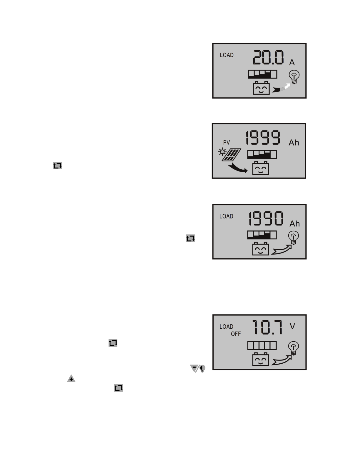
3.9 Reviewing and Setting Recovering Voltage for Voltage Condition
!
As shown in the figure to the right, the displayed
number is the recovery number. After the
controller enters into a low voltage protection
state, and when the battery voltage recovers
to be higher than the recovering voltage, the
controller will reconnect the load loop
automatically. At this interface, press for over
5 seconds (>5 seconds). The number will start
to flicker, which means the controller enters into
the interface of setting the recovery voltage. Use
buttons and to adjust this parameter.
After finishing this set-up, press for over 5
seconds (>5 seconds) to exit this interface and
the controller can store this setting number.
!
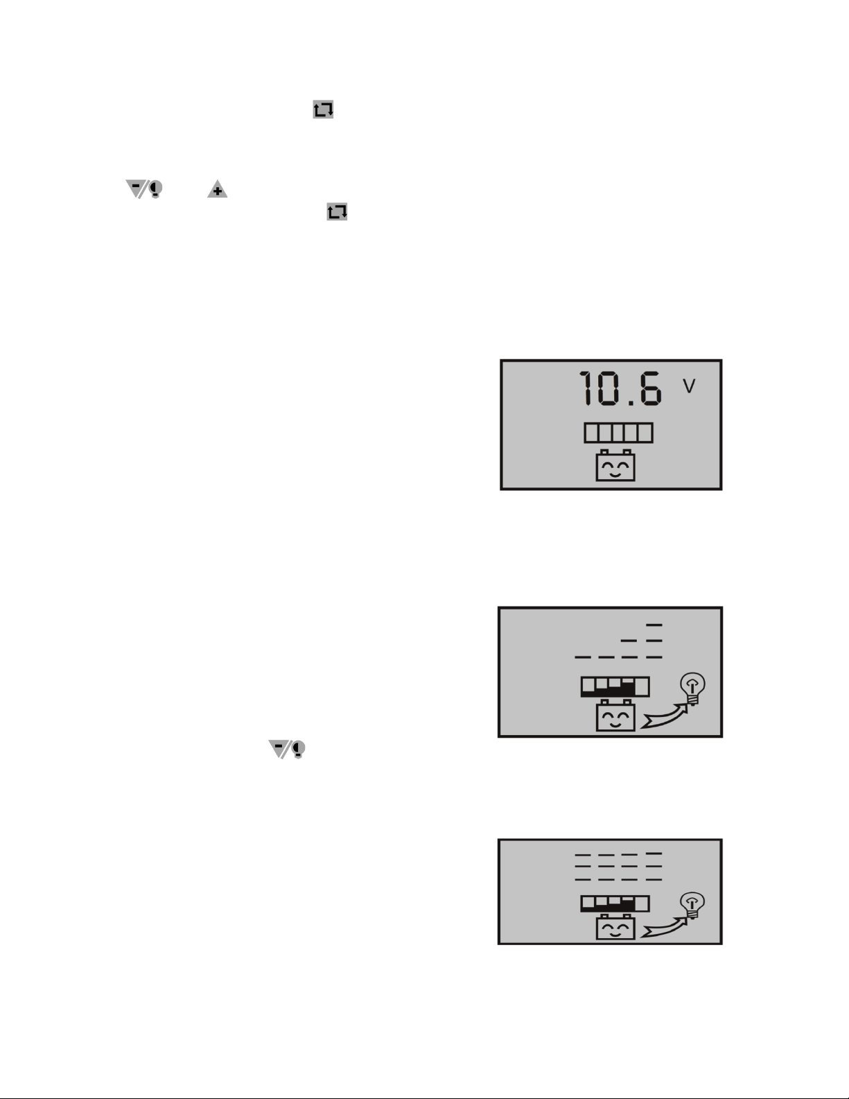
3.10 Reviewing and Setting the Voltage Where Controller Ceases Charging
As shown in the figure to the right, the displayed number is the voltage where the
charger will cease charging. When the battery voltage reaches this voltage, the
controller will disconnect the charging loop to prevent the battery from
overcharging. After the battery voltage drops, the controller will reconnect the
charging loop. At this interface, press for greater than 5 seconds (>5
seconds). The number will start to flicker, which means the controller enters into
the interface to set the voltage where the controller ceases charging. Use buttons
and to adjust this parameter. After finishing this set-up, press for
greater than 5 seconds (>5 seconds) to exit this interface and the controller can
store this setting number.
!
3.10 Reviewing and Setting the Load Mode
Shown in the figure to the right is the reviewing
surface of the load mode.
•24h – Indicates normal mode. Loads are
under the condition of supplying power
without breakdown.
•1h-23h – Indicates delayed mode of light
control. Load starts to supply power after
dark and sun down after working for the
delayed setting hours.
•0h – Indicates Light Control. Load starts
to supply power after dark and stops after
dawn.
!
6
At this interface, press for greater than 5
seconds (>5 seconds). The number will start to
flicker, which means the controller enters into
the interface to set the load modes. Use buttons
and to adjust this parameter. After
finishing this set-up, press for greater than 5
seconds (>5 seconds) to exit this interface and
the controller can store this setting number.
!
Breakdown And Disposal
Low Voltage Protection and Disposal
!
If the screen displays the information as shown
in the figure to the right, it means the battery
voltage is lower than the protection voltage. The
controller enters into the low voltage protection
state and the load loop disconnects. Use the
solar panels or alternate charger to charge
the battery. When battery voltage recovers to
the protection voltage, the controller will recover
to supply power for load, and enter into the
working state.
!
Overloading Protection and Disposal
If the screen displays the image shown in the
figure to the right, and the light flickers, it mean
the current of the load loop is 1.2 times that of
the rated current within 3 seconds, and the
controller is at an overloading state. After
removing some loads, the controller will supply
power to the loads automatically within seconds,
or you can press to recover the power
supply compulsively.
Short-Circuit Protection and Disposal
!
If the screen displays the image shown in the
figure to the right, and the light flickers, it means
there is a short-circuit in the load loop, and the
controller is in a short-circuit protection state.
Please check whether the loads are damaged
and whether the connecting cables are short-
circuited. After eliminating the breakdown, press
!
7
to recover the power supply for the loads.
Breakdown and Disposal of Solar Panels
Sign flickering means the controller does not detect the existence of solar
panels. Please check whether the connection with the solar panels is in good
condition, and check whether the cables connecting the solar panels and the
controller are in open-circuit condition.
Load Impulsion Breakdown
If flickers when you turn on the load, it means the starting impulsion current
is more than twice that of the rated working current. Please restart the controller
four times. Other exceptional conditions: Please contact the distributor or
manufacturer.
Charge Controller Specifications
Electrical Characteristics
Parameter
PWM30CC-LCD
Rated Working Voltage
12V/24V
Rated Working Current
30A
Solar Input Voltage
≤48V
Float Charging Voltage (adjustable)
13.8V/27.6V
Low Voltage Protection (adjustable)
10.7V/21.4V
Low Voltage Recovery (adjustable
12.5V/25.0V
No Load Loss
≤30mA
Loop Voltage Drop
≤170mV
Temperature Compensation
-4mV/Cell/°C
Technical Specifications
Parameter
PWM30CC-LCD
Max. Wire Size
AWG #7 (16mm2)
Working Temperature
-10°C to 60°C (14°F to 140°F)
Storage Temperature
-30°C to 70°C (-22°F to 158°F)
Temperature Compensation
≤90%, No Condensation
Dimensions
90x188x48 mm (3.54x7.40x1.89 in)
Weight
360g (12.7 oz.)

Other Renogy Inverter manuals

Renogy RNG-INVT-700-12V-P2 User manual

Renogy

Renogy RNG-INVT-700-12V-P2 User manual

Renogy Firefly User manual

Renogy

Renogy Firefly User manual

Renogy 500W User manual

Renogy

Renogy 500W User manual

Renogy Solar 200W 2.4kWh Extension Solution User manual

Renogy

Renogy Solar 200W 2.4kWh Extension Solution User manual

Renogy Off-Grid Kit Configuration guide

Renogy

Renogy Off-Grid Kit Configuration guide

Renogy RNG-INVT-700- 12V-P2 User manual

Renogy

Renogy RNG-INVT-700- 12V-P2 User manual

Renogy Wanderer 30A User manual

Renogy

Renogy Wanderer 30A User manual

Renogy 700w User manual

Renogy

Renogy 700w User manual

Renogy RSP8TC-G1 User manual

Renogy

Renogy RSP8TC-G1 User manual

Renogy PGH1 Series User manual

Renogy

Renogy PGH1 Series User manual

Renogy Element Series User manual

Renogy

Renogy Element Series User manual

Renogy PGH1-10111S User manual

Renogy

Renogy PGH1-10111S User manual

Renogy E.FLEX 21W R-SC001 User manual

Renogy

Renogy E.FLEX 21W R-SC001 User manual

Renogy Solar 400W 2.56kWh Extension Solution User manual

Renogy

Renogy Solar 400W 2.56kWh Extension Solution User manual

Renogy R-SP001 User manual

Renogy

Renogy R-SP001 User manual

Renogy PCL Series User manual

Renogy

Renogy PCL Series User manual

Renogy 100W Solar Suitcase User manual

Renogy

Renogy 100W Solar Suitcase User manual

Renogy R-INVT-PGH1-20111S-G1 User manual

Renogy

Renogy R-INVT-PGH1-20111S-G1 User manual

Renogy PWM10CC User manual

Renogy

Renogy PWM10CC User manual

Renogy REGO User manual

Renogy

Renogy REGO User manual

Renogy Solar 440W 3.84kWh Extension Solution User manual

Renogy

Renogy Solar 440W 3.84kWh Extension Solution User manual

Popular Inverter manuals by other brands

YASKAWA VS mini C Series instruction manual

YASKAWA

YASKAWA VS mini C Series instruction manual

Goobay 67921 user manual

Goobay

Goobay 67921 user manual

Zeus Appollo Z21 Series installation manual

Zeus Appollo

Zeus Appollo Z21 Series installation manual

Aybey Elektronik AE-LIFT Series user manual

Aybey Elektronik

Aybey Elektronik AE-LIFT Series user manual

SMA Windy Boy 6000 operating instructions

SMA

SMA Windy Boy 6000 operating instructions

Generac Power Systems APS 6.0 Operating & installation manual

Generac Power Systems

Generac Power Systems APS 6.0 Operating & installation manual

V-TAC VT-6605305 instruction manual

V-TAC

V-TAC VT-6605305 instruction manual

Redback RB4 5KVA manual

Redback

Redback RB4 5KVA manual

Briggs & Stratton 1768-0 installation manual

Briggs & Stratton

Briggs & Stratton 1768-0 installation manual

Zeversolar Zeverlution 3680 Installation and operating instructions

Zeversolar

Zeversolar Zeverlution 3680 Installation and operating instructions

SOLIS 4G Mini user manual

SOLIS

SOLIS 4G Mini user manual

TECO F33 Series instruction manual

TECO

TECO F33 Series instruction manual

FoxESS LV5200 user manual

FoxESS

FoxESS LV5200 user manual

Turbo Energy Lithium Slim Series Quick installation guide

Turbo Energy

Turbo Energy Lithium Slim Series Quick installation guide

Cotek S Series user manual

Cotek

Cotek S Series user manual

ZIEHL-ABEGG Fcontrol Basic operating instructions

ZIEHL-ABEGG

ZIEHL-ABEGG Fcontrol Basic operating instructions

BIGGER BOYZ TOYZ AUSTRALIA PTY.LTD BBT-GEN-3.5KWINV owner's manual

BIGGER BOYZ TOYZ AUSTRALIA PTY.LTD

BIGGER BOYZ TOYZ AUSTRALIA PTY.LTD BBT-GEN-3.5KWINV owner's manual

Northern Lights ONL843NW4 Operator's manual

Northern Lights

Northern Lights ONL843NW4 Operator's manual

manuals.online logo
manuals.online logoBrands
  • About & Mission
  • Contact us
  • Privacy Policy
  • Terms and Conditions

Copyright 2025 Manuals.Online. All Rights Reserved.