Renu Electronics GWY-500 User manual

GWY-500
(Profibus Gateway)
USER’S MANUAL

COPYRIGHT NOTICE
This manual is a publication of Renu Electronics Pvt. Ltd. and is provided for use by its customers only.
The contents of the manual are copyrighted by Renu Electronics Pvt. Ltd.; reproduction in whole or in part, for use other
than in support of Renu Electronics Pvt. Ltd. equipment, is prohibited without the specific written permission of Renu
Electronics Pvt. Ltd..
SERVICE
If service is required then pack the unit in its original packaging container or, if unavailable, any suitable rigid container.
If a substitute container is used, surround the unit with shock absorbing material; damage in shipment is not covered
by the warranty. Include a letter with the unit describing the difficulty and Hardware Revision and Software Version.
Send to the following address:
Renu Electronics Pvt. Ltd.
Survey No. 2/6,
Baner Road,
Pune-411045
India
All returns will be tested to verify customer claims of noncompliance with the product warranty. Improper return
packaging, which makes verification impossible, will void the warranty. If noncompliance is verified and is not due to
customer abuse or the other exceptions described with product warranty,Renu Electronics Pvt. Ltd. will, at its option,
repair or replace the Product returned to it, freight prepaid, which fail to comply with the foregoing warranty, provided
Renu Electronics Pvt. Ltd. is notified of such noncompliance within the one-year warranty period.
ASSISTANCE
This manual is designed to provide the necessary information for trouble-free installation and operation of your new
Gateway product. However, if you need assistance, please call Renu Electronics Pvt. Ltd. at 91-20-27292840 or visit
our web site at www.renuelectronics.com
MANUAL REVISION
If you contact us in refference to this manual, please include the following document number
Name : Profibus Gateway (GWY-500-B) User’s Manual
Part Number : URML204
Document : UMAN\GWY-500-B\0106
Revision : Revision4
RevisionNumber Date Description
Preliminary 10/11/2005 First Release
Revision0 19/01/2006 GSD file location is specified.
Revision1 17/03/2006 GSD file location is specified. GSD file model name is changed.
Communicationand IBMcable detailsare added.
Revision2 14/02/2007 GWY-500features(Default CommunicationRegister,Recipes, Control
wordforIDB,diagnostic Information) added.Cable details for thomson
controller, optomux,ABDF1,Hostlink & yokogawa are added.
Revision3 08/10/2007 Setupof ProfibusOption Card with Siemens ProfibusMaster isrevised.
(Section8.2)
Revision4 02/08/2010 NS to GWY-500 cable connections are revised.

Warranty Certificate
For New product: This product is warranted against defects in materials and workmanship for a period of 12 months
from the date of shipment to Buyer.
For Rectified Products:Any product that will be replaced will have Warranty for 6 months or upto Original Product
Warranty period whichever is greater.
The warranty is limited to repair or replacement of the defective unit at the option of the manufacturer. This warranty is
void if the product has been altered, misused, dismantled, or otherwise abused.
ALL OTHER WARRANTIES, EXPRESSED OR IMPLIED,ARE EXCLUDED, INCLUDING BUT NOT LIMITED TO THE
IMPLIED WARRANTIES OF MERCHANTABILITYAND FITNESS FOR A PARTICULAR PURPOSE.
MAINTENANCE & SERVICE :There are no parts that can be serviced by the user. Service should be performed on a
unit substitution basis only. Do not attempt to remove, replace or service any printed circuit board, components or any
hardware/software related with display product. If problem within the display product occurs, contact the factory for
service information or repair.
NOTE : Renu Electronics Pvt. Ltd. is dedicated to providing complete customer service and customer satisfaction. If you
have any comments or criticisms about how to improve the product features/reliability, Please make a note of the
problem/improvement and notify us. We are always open to new ideas and improvements. So please let us know your
ideas and comments.
IMPORTANT
Gateway Products are intended to be Protocol Converters/Data Sharer devices
that can also take control actions on request of device being connected. It is assumed that
user is well acquainted with the PLC / Inverters / Controllers being used.
Any Mechanical or Electrical Modification to this Unit will
void all Warranties.

Contents
INTRODUCTION 1
1.1 Purpose of this manual 2
1.2 Introduction to Gateway 2
1.3 GWY-500 Specifications 4
HARDWARE 5
2.1 Dimensional details And Mounting Instructions 6
2.2 Communication Port Details 7
2.3 LED Status 10
GETTING STARTED 12
3.1 Introduction To Profibus 13
3.1.1 Protocol Architecture 13
3.1.2 Device Types 14
3.1.3 PROFIBUS-DP Characteristics 15
3.1.3.1 Bus Access Protocol 15
3.1.3.2 Data Throughput 16
3.1.3.3 Diagnostic Functions 16
3.1.3.4 Protection Mechanism 16
3.1.3.5 Network States 17
3.1.4 Device Data Base Files 17
3.1.5 Profiles 18
3.2 Introduction To GWY-500 18
3.3 GWY-500 Configuration 19
3.4 Configuration of GWY-500 (IBM Download) 19
3.4.1 When GWY-500 can accept configuration? 20
GWY-500-B FEATURES 21
4.1 Gateway Modes 22
4.1.1 Master-Master Configuration 22
4.1.2 Master-Slave Configuration 25
4.2 Repeat Cycle 28
4.3 Control Word 28
4.4 Error Indication Bit 29
4.5 Communication Parameters 29
4.6 Default Communication Register 30
4.7 Recipes 31
4.8 Control word for IDB 32
4.9 Diagnostic 33
4.10 Profibus Connection Status word 33
NOTE ON COMMUNICATION DRIVERS 34
5.1 Note On Communication Drivers 35
TYPICAL PROJECTS 39
6.1 Project Setup 40
6.2 Connect Toshiba Inverter as Profibus DPV0 Slave on Profibus Network with GWY-500 41
6.3 Connect Modicon PLC or other Modbus Slave devices as Profibus DPV0 Slave on
Profibus Network with GWY-500-B 43
6.4 Connect SCADA Software on Profibus Network 45
CONFIGURATIONSOFTWARE 47
7.1 System Requirements 48
7.2 Installation Instruction 48

PROFIBUS MASTER SETUP 49
8.1 Setup Of GWY-500 with Omron Profibus Master 50
8.2 Setup Of GWY-500 with Siemens Profibus Master 64
APPLICATIONS 76
9.1 Possible Applications of GWY-500-B 77
CABLE DIAGRAMS 79
10.1 Communication Cables 80
10.1.1 TOSHIBA VF-S11 TO GWY-500 80
10.1.2 TOSHIBA T1 LINK PORT TO GWY-500 81
10.1.3 OMRON MASTER PROFIBUS PORT TO GWY-500 PROFIBUS PORT 82
10.1.4 SIEMENS MASTER PROFIBUS PORT TO GWY-500 PROFIBUS PORT 83
10.1.5 NS TO GWY-500 84
10.1.6 THOMSON TECHNOLOGY CONTROLLER TO GWY-500 85
10.1.7 OPTOMUX TO GWY-500 86
10.1.8 YOKOGAWA CONTROLLER TO GWY-500 87
10.1.10 AB MICROLOGIX SERIES PLCs TO GWY-500 (EC-P-027A-00) 88
10.1.9 AB SLC DH485 PORT TO GWY-500 (EC-P-007-00) 89
10.1.12 OMRON CQM1 PLC TO GWY-500 (EC-P-006B-00) 90
10.1.11 A B SLC DF1 PORT TO GWY-500 (EC-P-027B-00) 91
10.1.13 OMRON CQM/CPM CMOS PORT TO GWY-500 (EC-P-006A-00) 92
10.2 IBM Cables 93
10.2.1 IBM CABLE FOR GWY-500 93

Introduction
1
DocNo: UMAN\GWY-500-B\0106
REVISION4
INTRODUCTION
In this chapter. . . .
♦Purposeof thismanual
♦IntroductionTo Gateway
♦GWY-500-BSpecifications

Introduction
2
DocNo: UMAN\GWY-500-B\0106
REVISION4
1.1 Purpose of this manual
Thankyou for purchasingGWY-500Product from RenuElectronics Pvt. Ltd..
Theintention ofthis UserManual isto providea guidefor Safeinstallation, Configuration and operation of GWY-500
Functionality of all the Gateway models is same. Read this User manual thoroughly before installing and operating
GWY-500,
Thisdocument is basedon information availableat the timeof its publication.While efforts havebeen made tobe accurate,
theinformation inthis document may not coverall thedetails orvariations inhardware orsoftware. Featuresdescribed
herein may not be present in all hardwares. Renu Electronics Pvt. Ltd. reserves the right to update information in this
publicationwithout priornotice.
1.2 Introduction to Gateway
Gatewayis aProtocol Converter/ Datasharer fordevices like PLCs,inverters (AdjustableSpeed Drives),and otherControl-
lers.Gateway has two serial ports thatconnect withtwo differentdevices.These devices share datathrough Gateway.
Gatewaycommunicates witha deviceto get theinformation requiredby thedeviceconnected on theother port.The device
thatrequires datais calledDestination Deviceand thedevice thatprovides datais calledSource Device.Information could
be,
-value ofa PLCregister.
- status of a PLC coil.
-Command fromSource Deviceto Destination Device to performany actionat thedestination end.
ConfigurationOfGateway
Note: Please refer ‘IBM Download’ in section 3.4.
COM1 / PLC 1
(RS232/RS485/CMOS)
Profibus - DP (Slave)
PLC1
OK
Profibus
RenuElectronicsPvt.Ltd.
SurveyNo. 2/6, Baner Road,
Pune-411045INDIA
GWY-500-B
DC+
DC-
EARTH
}24VDC
+/- 10%
C US
LR 109782-2
Pending

Introduction
3
DocNo: UMAN\GWY-500-B\0106
REVISION4
NormalOperation:
ConnectProfibus Masterdevice to Gatewayvia Profibusport andserial device(PLCor Inverter)via thePLC’s communi-
cationsport (correctcables are required) and thePLCs caneasily exchangeinformation with the Profibus-DP devices.
PLC1
Profibus-DP Protocol
PLC (Profibus Master)
PLC
Drive Motor
Node n
PID Controller
~
~
Node 1
XProtocol
GWY-500-B
Node 2
PLC

Introduction
4
DocNo: UMAN\GWY-500-B\0106
REVISION4
1.3 GWY-500 Specifications
Power : 24 V DC, 2.5 W
LED’s : 3 LED’s for status indication
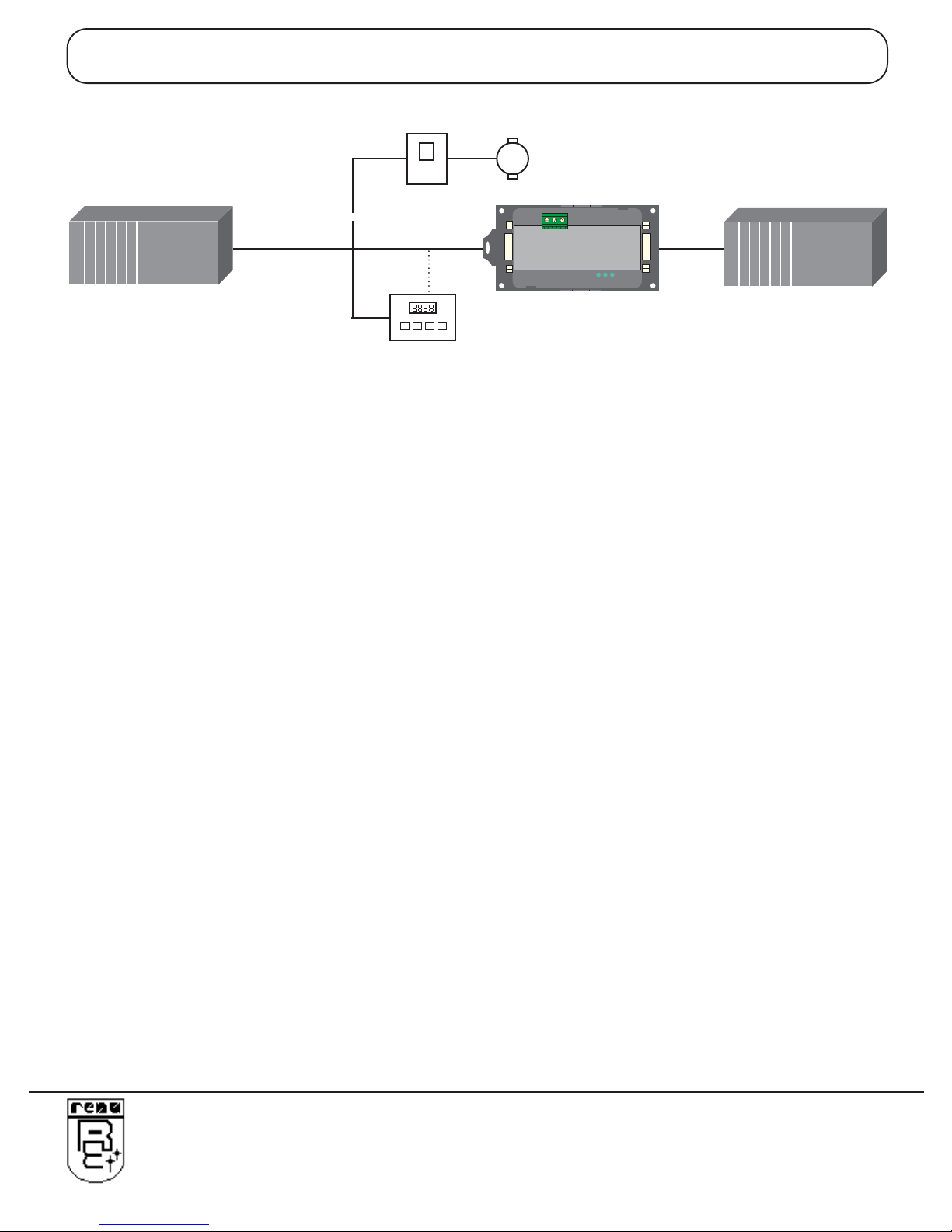
CommunicationPorts : 2Communication portswith
COM1 : RS232 / RS422 / RS485 / CMOS
COM2 : Profibus-DPV0Slave (2 WireRS485)
(Isolationbetween communicationports andPower supply, through DC-DC coupler is 1 KV)
COM1 /PLC1 : Connects to PC for setup download or connects to PLC1 at runtime.
COM2/ PLC2 : Profibus-DPV0Slave (2Wire RS485)
(Isolationbetween communication ports, through opto-isolationis 1KVrms for 1 min)
ProfibusBaudRate : 9.6k, 19.2k, 45.45k, 93.75k, 187.5k, 500k, 1.5M, 3M, 6M, 12M Bit/s
(Autodetect)
GSDFile : Suppliedin the InstallableSoftware CD.
GSDFile Name : RENU0A0E.GSD
I/Odata : 100Word Input, 100 WordOutput
*Profibus SlaveID : 0 - 125(ID shouldbe providedthrough GatewaySetup Software/PLC2
Settings/Advanced)
OperatingTemperature : 0oto 60oC
StorageTemperature : -20oto 80oC
Humidity : 10%to 90%(Non condensing)
Mounting : DINrail orback panelmounting
Dimensions(DINrail) : 105mm(L)X40mm(D) X51mm(W)
Weight : 125gm approx.
Certifications : CE with UL certification
Immunity to ESD : Level3asper IEC1000-4-2
Immunityto Transients : Level3asper IEC1000-4-4
Immunityto RadiatedRF : Level3asperIEC1000-4-3
Immunityto ConductedRF : Level 3asperIEC1000-4-6
Emissions : EN55011CISPRA
Note1 : If Toshiba VF-S11 Inverter is connected at COM1 of GWY-500, station number is detected automatically at
power ON and that station number is assigned as a Profibus Slave ID.
InverterID Canbe setfrom 0-99.
Note2 : Once You install Gateway Setup Software, you will find GSD file at:
“C:\Program Files\Gateway3.XX\GWY-5oo(Profibus Gateway)\GSD”. Thisis the defaultpath.Theactual pathis
wherethe user hasinstalled Gateway SetupSoftware.
Note3 : GSD file is also provided in the CD along with the Installable software.
Note4 : Previously the model name in GSD file was GWY-500 Now it is changed to GWY-XXXXX to support all the
productshaving Profibusport.
Note5 : Profibus detects baud rate automatically. So baud rate field in PLC2 Settings of Gateway software does not
havemeaning specificmeaning.
Source ID and Destination ID related to Profibus driver does not have specific meaning. Profibus ID is set by
Gatewayconfiguration software.(PLC2 settings/Advanced).

Hardware
5
DocNo: UMAN\GWY-500-B\0106
REVISION4
HARDWARE
In this chapter. . . .
♦DimensionalDetails AndMounting Instructions
♦CommunicationPort Details
♦LED Status

Hardware
6
DocNo: UMAN\GWY-500-B\0106
REVISION4
2.1 Dimensional details And Mounting Instructions
GWY-500 -B unit can be mounted on a back panel or on a DIN rail or can be left hanging. It comes with a separate DIN rail
plate when it is packed. User will have to attach the DIN rail plate to the unit if it has to be mounted on a panel or DIN rail. If
it has to be left hanging, make sure to screw the cables to the DB9 connectors on the Gateway unit. DIN rail plate also has
the provision to screw the unit to the back panel. Following drawing shows how to attach the DIN rail plate to the unit:
Followinstructions given below:
1. Attach the DIN rail plate to the unit using the clamps on the DIN rail plate.
2. Pull out the clip of the plate.
3. Put the unit on the DIN rail.
4. Push the clip in to secure the unit on the DIN rail.
GWY-500 unit is shipped with a separate DIN rail plate which has to be attached to the unit, if needed. User can use the
unit with or without the DIN rail plate. Following sketch shows mounting details of GWY-500 with the DIN rail plate.
DIN rail
clamp
DIN rail
clip
GWY-500
Slot for
clamp
40

Hardware
7
DocNo: UMAN\GWY-500-B\0106
REVISION4
2.2 Communication Port Details
GWY-500 has two communication ports COM1 and COM2. COM1 port is compactible to RS232/ RS422/ RS485 and
CMOS signal levels. Pinout of this port is given as follows:
TX-(RS422/RS485)
DB9 Female
1
5
9
6
+5VDC*
(DO NOT USE)
SignalGround
RX+(RS422/RS485)
RXD(RS232C/CMOS)
TXD(RS232C)
TX+(RS422/RS485)
TXD(CMOS)
RX-(RS422/RS485)
6
8
9
72
4
5
3
1
PLC1 / COM1
*Do not use pin no. 6 of PLC1 / COM1.
**Referour website (www.renuelectronics.com) foryour specificCablerequirements

Hardware
8
DocNo: UMAN\GWY-500-B\0106
REVISION4
Pin Name SignalLevel Description
1. TX+ RS422/RS485 DifferentialTransmit +,alsoreferred asTXA
2. TXD RS232 Transmit
3. RXD RS232/ CMOS Receive
4. RX+ RS422/RS485 DifferentialReceive +,alsoreferred asRXA
5. GND - Signal Ground common to all signals.
6. +5VDC - DO NOT USE
7. TXD CMOS Transmit
8. TX- RS422/RS485 Differential Transmit-,also referredasTXB
9. RX- RS422/ RS485 DifferentialReceive-,also referredasRXB
PinDescription
User can convert RS485 4 wire + Signal Ground system to a 2 Wire + Signal Ground system by shorting following
signals in the communication cable:
TX+
TX- A
RX+ B
RX-
SG SG
Note: If user has attached shield to Earth on Device end, leave the shield open on Gateway end. If user has
connected shield to Signal Ground on Device end, connect shield to Signal Ground on Gateway end.
A and B are polarity insensitive. Twisted pair cable should be used for RS485 Network.
Upto 31 Devices can be multi-dropped on RS485 port of Gateway.

Hardware
9
DocNo: UMAN\GWY-500-B\0106
REVISION4
+5V DC
300Ohm
220Ohm
300Ohm
B - Data Line
A - Data Line
Data Ground
Data Line: The Profibus user group recommends the following color coding for the data signal lines:
A-Data Line = Green B-Data Line = Red
These data signal lines must be connected to the corresponding signal terminals or pins at the master unit
and other stations (i.e.AtoA, B to B).
RTS: The signal RTS (TTL signal relative to Data Ground) is meant for the direction control of repeaters in
case repeaters without self control capability are used.
+5V DC, Data Ground: The signals +5V DC and Data Ground are meant to power an externally mounted
bus terminator.
The powering of the 220 © termination resistor ensures a defined idle state potential on the data lines. To
ensure proper functioning up to the highest baud rate, each bus segment has to be terminated at both ends
of the cable.
B (-) Data Line
A (+) Data Line
DB9Female
1
5
9
6
+5V DC
Data Ground
RTS
Shield / Functional
Ground
6
84
5
3
1
Profibus-DP Slave
(TTL Direction control for repeaters)
(Supply Voltage for terminator resistance)

Hardware
10
DocNo: UMAN\GWY-500-B\0106
REVISION4
2.3 LED Status
There are 3 Bicolor LEDs for status indication.
BicolorLEDsstatus:
LED
OK Green OFF No Firmware
Flashing IBMDownload
ON Bothside (COM1and COM2)communication OK
Red OFF ConfigurationOk
ON ConfigurationFault
PLC1 Green OFF No data receivedon PLC1Port
Flashing Receivingdata on PLC1Port
ON -
Red OFF No error in PLC1 attach or while block execution
Flashing PLC1attach erroror error while block execution
ON -
Profibus Green OFF No data receivedonProfibus Port
Flashing Receivingdata on ProfibusPort
ON -
Red OFF Dataexchangewith ProfibusMaster
Flashing -
ON Nodata exchangewith ProfibusMaster

Hardware
11
DocNo: UMAN\GWY-500-B\0106
REVISION4
Note: At power on , OK LED is steady ON for approximately 5 seconds. Here it sends requests to device connected
on serial port .
If a device connected on serial port is not detected , OK LED blinks for 10 seconds and again steady for
approximately 5 seconds as Profibus Gateway (Gateway 500) sends requests to serial ports device.
This process is continued until a device connected on serial port is detected.
If that device is detected, Profibus port is initialised.
After successful Profibus initialisation, gateway 500 starts exectuting the project blocks.
At this point , Ok LED is steady ON. serial port and Profibus LED are blinking.
Now , if the gateway 500 detects that Profibus master is not present then it stops the block execution and
continuouslywaits forProfibus Master.
At this time OK LED is steady on and serial port and Profibus LEDs are off.

Getting Started
12
DocNo: UMAN\GWY-500-B\0106
REVISION4
GETTING STARTED
In this chapter. . . .
♦IntroductionToProfibus
♦IntroductionToGWY-500-B
♦GWY-500-BOperation

Getting Started
13
DocNo: UMAN\GWY-500-B\0106
REVISION4
3.1 Introduction To Profibus
PROFIBUSis avendor-independent,open fieldbusstandard forawide rangeofapplications inmanufacturing, process
andbuilding automation.Vendor independenceand openness areguaranteed bythe PROFIBUSstandardEN50170. With
PROFIBUS,devices ofdifferentmanufacturers cancommunicate withoutspecialinterface adjustments.ThePROFIBUS
familyconsists of three compatible versions:
Highspeed PROFIBUS-DP
DP stands for Decentralised Periphery. It is optimised for high speed and low cost interfacing,
especiallydesigned forcommunication between automation controlsystems anddistributed I/O
atthe device level.
ProcessAutomation PROFIBUS-PA
PA stands for ProcessAutomation. It permits sensors and actuators to be connected on one
commonbus lineeven in intrinsically-safeareas. Itpermits data communication andpower
supply overthe bususing 2-wiretechnology according the internationalstandardIEC1158-2.
Higherlevel PROFIBUS-FMS
FMS standsfor FieldbusMessage Specification. Thisversion isthe generalpurpose solutionfor
communicationtasks ata higherlevel. Powerful services open upa widerange ofapplications
and provide great flexibility. It can also be used for extensive and complex communications tasks.
Uniformbus access PROFIBUS-DPand PROFIBUS-FMSuse thesame transmission technology and auniform bus
protocol access protocol. Thus, both versions can be operated simultaneously on the same cable.
However, FMSfield devicescannot becontrolled byDPmastersor viceversa.
Note: It is not possible to exchange one of these family members by another family
member.This willcause faultyoperation.
Therest of this section onlydescribes PROFIBUS-DP.Protocol architecture.
3.1.1 Protocol Architecture
OSI ThePROFIBUS protocolarchitecture isoriented onthe OSI(Open SystemInterconnection)
referencemodel inaccordance withthe internationalstandard ISO7498. Layer1 (physicallayer)
of this model defines the physical transmission characteristics. Layer 2 (data link layer) defines
the bus access protocol. Layer 7 (application layer) defines the application functions.
DP-Profiles
DP- Extentions
DP- Basic Functions
NotDefined
Field Bus Data Link (FDL)
RS-485 / Fiber optics
UserInterfaceLayer
(7) ApplicationLayer
(6)Presentation Layer
(5)Session Layer
(4)TransportLayer
(3)NetworkLayer
(2)Data LinkLayer
(1) Physical Layer

Getting Started
14
DocNo: UMAN\GWY-500-B\0106
REVISION4
Layer 1, 2 anduser PROFIBUS-DP uses layers 1 and 2, and the user interface. Layers 3 to 7 are not
interface defined.This streamlinedarchitecture ensuresfast andefficient datatransmission. The
application functions which are available to the user, as well as the system and device
behaviourof thevariousPROFIBUS-DP devicetypes, arespecified in theuser interface.
Transmissionmedium RS-485 transmission technologyor fibreoptics areavailable fortransmission. RS-485
transmission is the most frequently used transmission technology. Its application area
includesall areas in which high transmission speed and simple inexpensiveinstallation
High-speed,inexpensive arerequired.Twisted pairshielded coppercable withone conductor pairisused.
Easy installation TheRS-485 transmission technology isvery easy tohandle. Installation ofthe twisted
paircable doesnot requireexpert knowledge. The bus structurepermits additionand
removalof stations orstep-by-step commissioningof the systemwithout influencing the
otherstations. Later expansions have noeffect onstations which are already inopera
tion. Transmission speeds between 9.6 kbit/s and 12 Mbit/s can be selected. One
unique transmission speed is selected for all devices on the bus when the system is
commissioned.
Cable length Themaximum cablelength depends onthe transmissionspeed The specified cable
lengths are based on type-A cable. The length can be increased by the use of repeaters.
The use of more than 3 repeaters in series is not recommended.
3.1.2 Device Types
PROFIBUSdistinguishes betweenmasterdevices andslave devices.
Master devices Master devices determine the data communication on the bus. A master can send
messages without an external request, as long as it holds the bus access right (the
token). Masters are also called active stations in the PROFIBUS standard.
DPM1, DPM2 There are two types of master devices: DP master class1 (DPM1) and DP master class2
(DPM2). A DPM1 is a central controller which exchanges information with the
decentralised stations (i.e. DP slaves) within a specified message cycle. DPM2 devices
areprogrammers, configurationdevicesor operatorpanels.They areused during com
missioning,for configurationof theDP system, or foroperation andmonitoring purposes.
Slave devices Slavedevicesare peripheraldevices.Typicalslave devicesincludeinput/output devices,
valves,drives, andmeasuring transmitters. They do nothave busaccess rights and they
canonly acknowledge received messages orsend messagesto the masterwhen
requested to do so. Slaves are also called passive stations.

Getting Started
15
DocNo: UMAN\GWY-500-B\0106
REVISION4
3.1.3 PROFIBUS-DP Characteristics
3.1.3.1 Bus Access Protocol
Layer 2 The bus access protocol is implemented by layer 2. This protocol also includes data
security and the handling of the transmission protocols and messages.
Medium Access Control TheMediumAccess Control(MAC) specifiesthe procedureswhich determine
when a station is permitted to transmit data. A token passing procedure is used to
handle the bus access between master devices, and a polling procedure is used to
handlethe communicationbetween amaster deviceand itsassigned slavedevice(s).
Token passing The token passing procedure guarantees that the bus access right (the token) is
assigned to each master within a precisely defined time frame. The token message, a
special message for passing access rights from one master to the next master, must
be passed around the logical token ring - once to each master - within a specified target
rotation time. Each master executes this procedure automatically. Auser can only
change the target rotation time, but is not recommended.
Polling procedure Thepolling ormaster-slave procedurepermitsthe master, whichcurrently ownsthe
token, to access its assigned slaves. The picture below shows a possible configuration
Theconfiguration showsthree active stations(masters) andsix passivestations
(slaves).
The three masters form a logical token ring. When an active station receives the token
message, it can perform its master role for a certain period of time. During this time it
can communicate with all assigned slave stations in a master- slave communication
relationship, and a DPM2 master can take the initiative to communicate with DPM1
masterstations in a master-mastercommunication relationship.
Multi-peer communication Inaddition tologicalpeer-to-peer datatransmission, PROFIBUS-DP providesmulti-peer
communication(broadcast andmulticast).
Broadcast communication:An active station sends anunacknowledged messageto
all other stations (masters and slaves).
Multicast communication: An active station sends an unacknowledged message to a
predetermined group of stations (masters and slaves).
Other manuals for GWY-500
1
This manual suits for next models
1
Table of contents
Other Renu Electronics Gateway manuals

Renu Electronics
Renu Electronics GWY-800 Series User manual

Renu Electronics
Renu Electronics GWY-900 User manual

Renu Electronics
Renu Electronics GWY-920LTE/LTE-S1 User manual

Renu Electronics
Renu Electronics GWY-500 User manual

Renu Electronics
Renu Electronics GWY-00 User manual

Renu Electronics
Renu Electronics GWY-610 User manual

Renu Electronics
Renu Electronics Gateway Instruction manual