Pace C 07, C 09, C 11
Tisch-Montage/Table assembly
Aufbau/Assembly
(Es werden 2 Personen benötigt/Two people are required.):
Kontrollieren Sie vor der Montage, dass Elektrokabel, Isolierungen und Bauteile nicht beschädigt sind. Bei Beschädi-
gungen darf das System nicht an das Stromnetz angeschlossen werden!
Check electric cables, isolations and components for intactness before assembly. In case of damage the system must not
be connected to the electric grid!
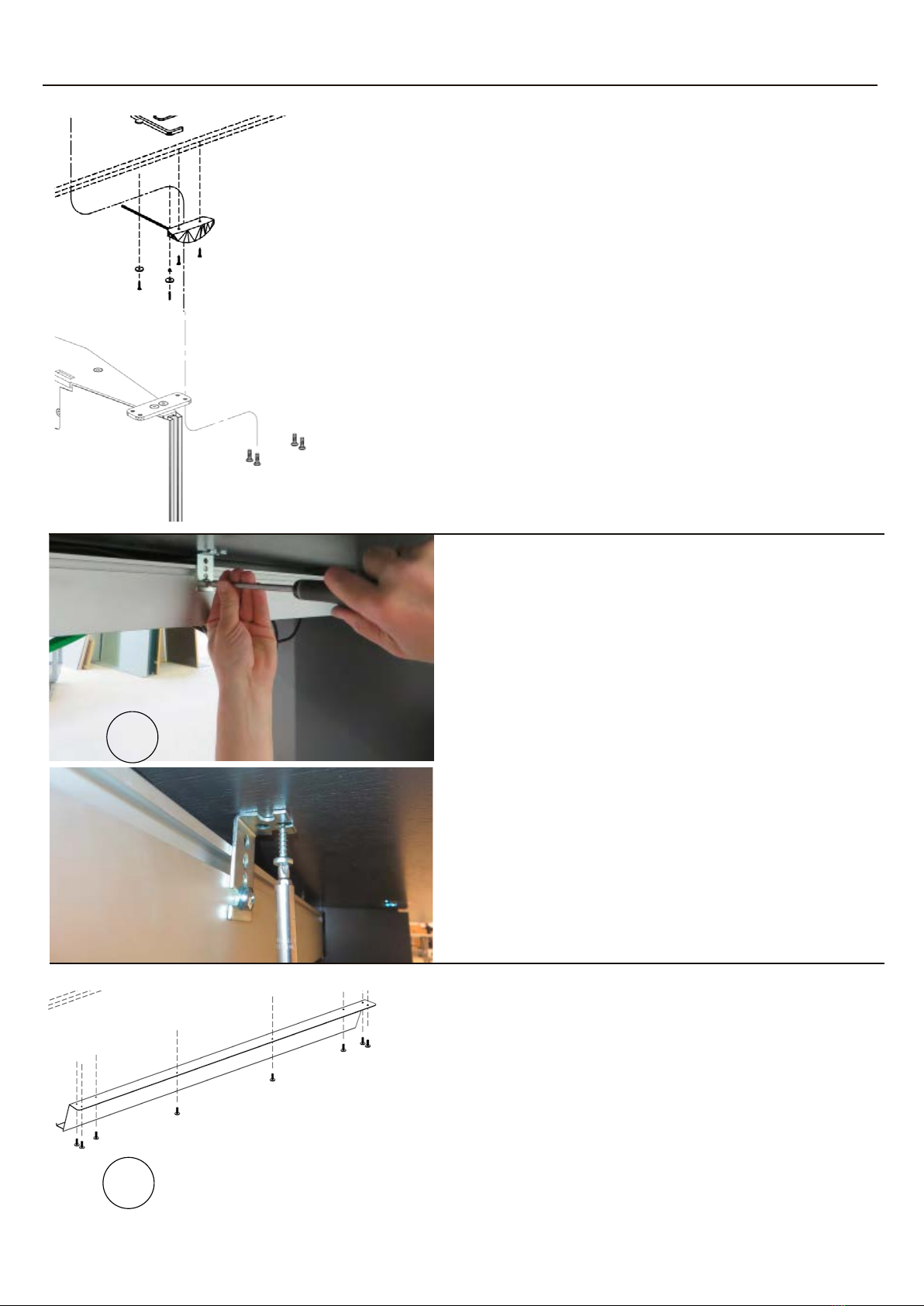
1.
Wangen und Gestell ausrichten: „Roter Punkt zu rotem Punkt“
= markiert hintere Tischkante.
- Zargenrahmen beidseitig mit je 5 Stück M10 x 20 Zylinder-
kopf fest verschrauben. (WICHTIG: Unterlegscheiben ver-
wenden).
- Kabelausgang oben: Kabelbaum nach unten durch den
Traversenrahmen führen.
1.
Align panels and rack: „Red point to red point“ = marks the rear
edge.
- Screw cross piece frameworks tightly on both sides with 5 pieces
M10 x 20 cylinder head screws. (IMPORTANT: Only screw with
washer).
- Cable exit on top: Place the cable tree downwards through the
cross-rail frame.
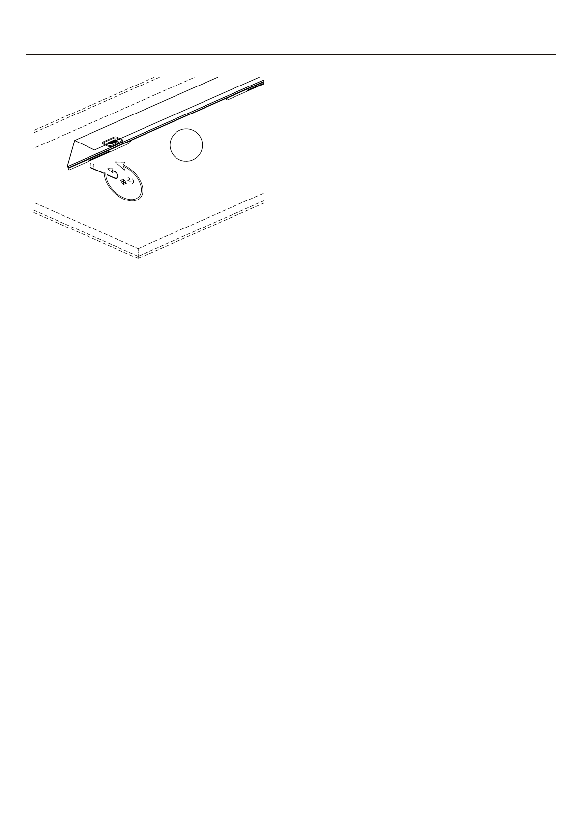
2.
Gestell nach bauseitiger Elektrozuführung („V1“ oder „V2“)
ausrichten.
- Für Anschluss der Datenkabel mit min. 2 Personen das
Tischgestell um ca. 30 Grad ankippen (nicht umlegen),
bauseitige Kabel von unten einstecken.
- Gestell vorsichtig zurückkippen, Anschlusskabel sauber
verlegen.
- Wenn Kabel auf dem Boden verlegt werden („V2“), müssen
diese in fest montierten Boden-Installationskanälen geführt
sein. Kabel nicht knicken und nur gemäß Herstellervorgaben
biegen.
2.
Align frame to the electrical on-site connection („V1“ or „V2“).
- For connecting data cables cant the table frame to about 30
degrees with min. 2 people (do not overturn), plug the on-site
cables from the bottom.
- Cant the frame gently back and lay the connection cable
neatly.
- Cables laid above floor cover(„V2“), have to be run in perma-
nently installed floor canals. Do not fold the cable and bend it
only in accordance with manufacturer‘s specifications.
1.
L/R Je 5 Stück
M10x20 mm
Zylinderkopf mit
Unterlegscheibe.
L/R Each 5 pieces
M10x20 mm
cylinder head with
washer.
„V2“ Bauseitige Kabel
über Belag nur in
festem Kanal verlegt.
„V2“ On-site cabling
above floor cover th-
rough/in canal.
„V1“Bauseitige Kabel
von unten aus dem
Bodentank kommend.
„V1“ On-site cabling
from below out of floor
tank.
2.