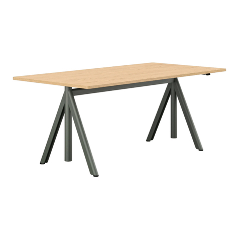
Renz Upsite U05 User manual

Upsite
Assembly and operating instructions

Upsite
Electrically height-adjustable desks
Dear customer,
Thank you very much that you have chosen a product from our company.
This instruction will explain how to assemble, use, and maintain the sit-and-stand-
up desk UPSITE. The assembly of the frame must be done as instructed. Changes
to the frame or an improper use may affect safety, functionality, and lifetime of the
product!
Please read the assembly and operating instruction before initial operation of the
height-adjustable workplace. Further, please keep this instruction together with the
product.
Wilhelm Renz GmbH + Co. KG
Assembly and operating Instruction for height-adjustable desks, model:
U05 (Frame type 1300 / TP Format 05 (1800 x 1000mm)
Product version 1300/05b dated March 03, 2021
U07 (Frame type 1300 / TP Format 07 (2000 x 1000mm)
Product version 1300/07b dated March 03, 2021
U09 (Frame type 1500 / TP Format 09 (2200 x 1000mm)
Product version 1500/09b dated March 03, 2021
U11 (Frame type 1500 / TP Format 11 (2400 x 1000mm)
Product version 1500/11b dated March 03, 2021
2

3
Upsite
Content
Content
1. Intended use 4
2. Previous knowledge 4
3. Symbols and safety instructions 4
4. Safety instructions 4
5. Before installing, uninstalling or trouble shooting 6
6. Before operating 6
7. Important information for resellers 6
8. Repairs / service 6
9. Maintenance / cleaning 6
10. Assembly 7
1) Overview freestanding desk (A) 7
2) Overview desk on toolboard (B) 8
3) Assembly of top frame (A,B) 9
4) Assembly of control unit (A,B) 10
5) Assembly of desk top (A;B) 11
6) Assembly of cabling: freestanding desk, cable chain (A) 11
7) Assembly of cabling: desk on toolboard, cable pipe (B) 12
8) Information on power cable (A,B) 15
9) Assembly of cable channel (A;B) 16
10) Assembly single unit container 17
11) Assembly and configuration of drawers 18
11. Initial operation 19
1) Procedure for initial operation 19
2) Connect drive units 19
3) Connect hand control 19
4) Connect power cable 19
12. Initialization / reset 20
13. Operation 20
1) Normal operation 20
2.) Save container / shelf stop position 20
3.) Thunderstorm danger 20
14. Trouleshooting 21
1) Possible problems and their solutions 21
2.) Click codes 22
15. Product dimensions 22
16. Technical data 22
17. Environmentally friendly disposal 23
18. Safety instructions magnets 23
19. Ergonomics 23
20. Tests and certificates 24
21. EC Declaration of Conformity 27

Upsite
Intended use, Safety instructions
4
1. Intended use
This sitting/standing table may only be used as an office desk in the professional sector. The electrically height-
adjustable table can be adjusted with the hand control to an individual working height for a sitting or standing user in
the height range between 740 and 1140 mm.
Modifications to the table are not permitted and will void the responsibility of the Wilh. Renz GmbH + Co. KG.
This sitting/standing table must be assembled, put into operation and maintained and functionally tested by qualified
personnel. In the event of improper use, improper handling or operation, the following may occur danger to persons or
objects.
2. Previous knowledge
The following knowledge is required for commissioning and assembly of the height-adjustable office desks:
- Basic knowledge of mechanical and electrical engineering
- Reading the operating instructions
3. Symbols and safety instructions
Danger: This safety note indicates an imminent danger to the life and health of persons!
Attention: This safety note indicates possible dangers due to electric current!
Danger: This safety note indicates a possible danger of crushing, which may occur in exceptional cases.
Note: The mains plug must be disconnected before the next operation!
Non-observance of these instructions may have health effects, result in life-threatening injuries and may
result in death. and damage to property!
4. Safety instructions
These operating instructions contain safety instructions which draw your attention to possible dangers and thus
enable safe operation of the sit-stand table. Please observe these safety instructions!
It is essential that you read and observe the operating instructions before assembling/commissioning the
sit-stand table!
Never open the COMPACTeco motor control unit! There is a risk of electric shock.
The height-adjustable office desks are not designed for continuous operation. The table top height must not be
adjusted without interruption for longer than the duty cycle specified on the type plate.
This device can be used by children aged 8 years and over and by persons with reduced physical, sensory
or mental abilities or lack of experience and knowledge if they have been supervised or instructed in the
safe use of the device and understand the resulting dangers. Children must not play with the device!
Cleaning and user maintenance must not be carried out by children without supervision.
Cables on the table must not be laid freely over the floor (danger of tripping). Use cable thresholds
connected to the floor. Cables must not be trapped between the foot stabilizer and the floorboard.
Subsequent sinking of the adjustable feet into different floor coverings is possible and must be observed.

Upsite
Safety instructions
5
Moving the furniture can damage cables leading into the floor (shearing, squeezing)! Cleaning personnel and
operators must be informed of these dangers.
Be sure to use the supplied power supply cable! Make sure that the power supply cable is not damaged.
Operating the sit-stand table with a damaged power supply cable is prohibited.
Attention: If the power cord of this device is damaged, it must be replaced by the manufacturer or its
customer service or a similarly qualified person in order to avoid hazards.
Modifications to the components of the table frame, including the motor control and the manual switches,
are prohibited!
Before connecting or disconnecting drives, manual switches or other accessories to the motor control
unit, always disconnect the power supply cable from the mains.
In the event of a malfunction (e.g. unintentional movement of the table top, e.g. if a key on the hand
control should become stuck), pull out the mains plug immediately! The mains plug serves as an
electrical disconnecting device and must be easily accessible at all times.
An electric strip (accessory) installed in the table may only be used up to the maximum power rating
to the connection value indicated on the strip.
At 230V / 50HZ and a fuse rating of 16A, 2300 watts are available for additional consumers.
Drive and electrification use a common supply line.
Protect the table frame and in particular all electrical components on the table including the hand switch
from moisture, dripping and splashing water! The table must not be operated in damp rooms.
Do not place any objects on the hand switches integrated into the table top. Danger of unintentional
operation and sudden height adjustment / danger of crushing.
There is a danger of crushing when changing the table top position! Therefore, make sure that there are
no objects or persons in the danger area and that you do not reach into the danger area!
Make sure that movable furniture does not get into the lifting area. (e.g. window sashes above the
table = danger of blockade, office chairs below the table = danger of blockade and tilting)
The integrated collision protection is a system protection and NOT a personal protection!
All moving parts of the table frame must have the required safety clearance of at least 25 mm from
adjacent components.
In combination with an attached toolboard (Fig. 2 / Variant B), there is a risk of hands and arms being
trapped between the underside of the cable duct and the top of the toolboard. If additional persons are
present, the operator is obliged to pay even greater attention in order to avoid damage.
The electric motor-driven sit-stand table must not be operated in an explosive atmosphere!
In the event of a fault, it may happen that the table top moves a little during each attempt to move away
before the safety switch-off starts. Please note a possible danger of crushing.
Collision protection is not active for all reset processes (section Initialization / Reset). The inner and outer
tubes move completely into each other directly under the table top. Note the possible danger of crushing
in the rack area. The operator must ensure that there are no persons in the danger area.
If the product is visibly damaged, makes unusual noises or causes an odour, it must no longer be installed
or used!
Lifting persons and / or objects with the aid of the table is prohibited! The table must not be used as a
climbing aid! The load capacity of the height-adjustable table is max. 50kg.

Upsite
Before commissioning, during operation, repairs / service, maintenance / cleaning
6
5. Before installing, uninstalling or trouble shooting
•Stop the height-adjustable desk.
Note: Turn off the power and unplug the power cord!
•Unload the height-adjustable office desk from any weight.
6. Before operating
•Makesurethatthetablehasbeenassembledinaccordancewiththeseinstructions.
•Checkthattheoperatingvoltageofthetablecorrespondstothelocalpowersupply.Thetablemayonlybe
operated with the voltage specified on the control unit.
During operation
•Iftheactuatorsorthecontrolunitcauseunusualnoisesorodoursduringoperation,disconnectthe
power supply.
•Makesurethatthecablesarenotdamaged.
7. Important information for resellers
Note: For each resale, be sure to include this manual with all safety instructions that every user needs to handle
the product safely.
8. Repairs / service
In case of a technical defect on this device, please contact us or our authorized after-sales service. You can find the
solution for simple possible error cases in the section Error Messages!
To avoid malfunctioning, all repairs must only be made by authorized service personnel. To repair the sit-stand table only
original spare parts are allowed.
The sit-stand table must not be handled or used improperly and no alterations may be made to the table frame or
electrification, otherwise Renz‘s warranty and declaration of CE conformity will lapse.
9. Maintenance / cleaning
At regular intervals, remove dust and dirt from the table frame, especially from the guide tubes, and make sure
that there are no damages or cracks. Please note the following for the Care of the wooden parts our care
instructions under: http://www.renz.de/files/renz.de/download/QP_E.pdf
Check all mounting screws for tightness and all connections, cables and plugs, as well as proper function.
The control unit, the handset and the table frame may only be cleaned with a dry or slightly moistened cloth.
Danger to persons!
Aggressive cleaning agents can cause damage or colour changes to the table frame. Therefore, only agents with a
pH value of 6-8 may be used. For cleaning and care of the wooden parts (table tops, etc.), please observe our care
instructions (care pass).
No liquid may enter the system (control unit, hand switch, cable and frame). Danger to persons!

Upsite
Assembly
7
10. Assembly
Use only screws for mounting the table frame in accordance with the assembly drawing!
Wrong screws may cause damage to the desk!
During assembly of the table frame, the power cable of the motor control must be disconnected from the mains supply !
Before installing and commissioning the sit-stand table, make sure that the product is acclimated to the values
for temperature and humidity for operation!
1) Overview freestanding desk (A)
Free-standing desk(A):
Lifting column with foot stabilizers 2 x # 1
Frame 1 x # 2
Pressure plates 2 x # 3
Control with carrier plate 1 x # 4
Cable chain(A) with cable ducts (Set) 1 x # 5 / A
Cable channel (Set) 1 x # 6
Bags of screws 1 x # 7
Assembly tools 1 x # 8
4 x Pressure bush, black
4 x M6 x 50
4 x Pressure bush, black
4 x M6 x 50
4 x M6 x 16
black
4 x M4 x 6
4 x M6 x 16
black
6 x 6,3 x 19
Coarse thread
# 6
# 2
# 4
# 3
# 1
# 1
# 5

Upsite
Assembly
8
2) ) Overview desk on toolboard (B)
Desk on toolboard (B):
Lifting column with foot stabilizers 1 x # 1
Frame 1 x # 2
Pressure plates 2 x # 3
Control with carrier plate 1 x # 4
Cable conduit (B) with cable ducts (Set) 1 x # 5 / B
Cable channel (Set) 1 x # 6
Bags of screws 1x # 7
Assembly tools 1 x # 8
Container with lifting column 1 x # 9
Left + right:
4 x Pressure bush, black
4 x M6 x 50
4 x M6 x 16
black
2 x M4 x 30
with spacer sleeve
# 6 # 2
# 4
# 3
# 1
# 9
# 5

Upsite
Assembly
9
3) Assembly of top frame (A,B)
Mount the frame to the two lifting columns one after the other. Only use the supplied M6x50 half-round head
screws and the pressure bushes according to the assembly drawing!
The maximum tightening torque for these screws is 7.5Nm. The maximum screw-in depth into the motor housing
is 5mm.
These screws may only be used in this position with pressure bush, otherwise there is a risk that the drive will be
damaged!
The movable longitudinal beam in the panel frame points to the cable duct (= visitor side).
Insert the lifting columns (#1) into the panel frame (#2), close to the attachment points. Hand tighten the frame
and lifting column with 4 M6 x 50 half-round head screws and 4 pressure bushes.
All parts must fit together tightly / gap-free.
Screw one pressure plate (#3) each under the motor housing. Use 4 pieces each M6 x 16mm screws,
black zinc plated.
The curved pressure plate (#3) pushes the motor housing into the plate frame when correctly mounted,
the perforated edge points upwards and towards the centre of the frame.
If all contact surfaces are close to each other (visual inspection), the frame is correctly mounted.
Finally tighten the two pairs of screws cylinder head M6 x 30 on the front side of the plate frame. The maximum
tightening torque for these screw connections is 7.5 NM.
Finally, retighten the
hidden screw connection
Left + right:
4 x Pressure bush, black
4 x M6 x 50
4 x M6 x 16
black

4) Assembly of control unit (A,B)
Insert the motor control into the recesses in the frame from above. The control points downwards. Select the
appropriate page for your table configuration. Pay attention to additional equipment such as electrical strips.
Plug 2x motor cable and 1x mains connection cable into the control unit.
There is space for cables above the control unit. Fix them to the brackets in the frame or with the additional cable
ties. Cables must not project beyond the upper edge of the frame. Do not run the cables over each other in the
area above the control unit. Cables must not be pinched, squeezed or nodded.
Use only the supplied 3-pole power supply cable or mains cable! If the power cord of this unit is damaged, it must
be replaced by the manufacturer or its customer service or a similarly qualified person in order to avoid hazards.
1 - RJ10 for DMS-sensor (SMARTneo sga)
2 - Minifit 6-pole for cascading cable
3 - C8 2-pole for mains power supply (AC)
4 - DIN for manual switch (HS)
5 - Minifit 8-pole for motor drives (M1, M2)
Upsite
Assembly
10

Upsite
Assembly
11
5) Assembly of desk top (A,B)
Insert the handset cable from above into the frame and to the control unit and fasten it according to the above
instructions.
Screw your table top to the table frame from below as shown in the drawing. There are 16 screws for this.
M6 x 16 round head with. All screw points are to be used.
6) Assembly of cabling: freestanding desk, cable chain (A)
Place the cable management (vertical cabling upper / middle) with magnets in the middle on the inside of the
desired table leg (Important: Accurately centered on the table leg, lower edge approx. 6cm above the floor).
Screw the chain holder with 4 round head screws M4x6 upwards against the pressure plate (#3).
Guide the cable upwards through the frame between table leg and the control. The cabling can only be mounted
on the inside.
When putting the desk into operation it is important to move the desk fully upwards. Ensure that the cable
management system is properly installed and that the cable routing is correct in all height positions. If necessary,
correct the height of the magnetic rails.
4 x M4 x 6
Magnets
Links
Links
Links downwards
Note:
(this side open)
(this side open)
Bending direction changes here

7) Assembly of cabling: desk on toolboard, cable pipe (B)
1. Combination table and container:
- Table and container must be aligned at the same height.
- To do this, first place the table frame with the mounted lifting column (free side with boom) on the container
lifting column.
- Adjust the elements with the adjustable gliders so that the lifting columns are aligned in all directions - verti
cal and horizontal. Only parallel columns ensure the proper function.
- Mount the frame parts with the screws.
Only qualified personnel may change the wiring!
2 Install the cable conduit correctly:
Dismantle the cover bottom on container U76 (screwed from below).
- The strain reliefs of the mains cable (orange arrows) must not be loosened or changed.
- Changes to the cabling only by qualified personnel
Upsite
Assembly
12

Upsite
Assembly
13
If any additional data cables are required, run them through the cable conduit parallel to the factory installed
power supply cables. Carefully fasten all cables in the specified position, observing the cable length.
- Mount the holder with 2x M4 x 30 and spacer sleeves on the plate frame.
All strain reliefs (7.1 + 7.2 + 7.3) must be mounted correctly.
Insert the cables tightly and without kinks under the cross beam of the table top into the cable channel.
Make sure that the cable tube is mounted exactly and parallel to the lifting column.
If necessary, you must align the adapter with the oblong holes.
ATTENTION / IMPORTANT: Make sure that the cable harness in the cable duct has the correct length. In any
height position, the cables must hang loosely in the cable duct. Never clamp any cables between moving
parts.
Carry out a visual inspection of the wiring. To do this, move the desk fully upwards and downwards and also
perform a reset run. An additional cable reserve is required for the reset run downwards.
Please note „Initial operation“. in this document.
Do not assemble the covering panel on the container until all work has been completed and the wiring has been
correctly connected.

- Align the components so that the guide tube is positioned upright in the cable duct.
- The cable conduit must be aligned parallel inside the cable duct, especially in the retracted position .
(Blue arrows).
Upsite
Assembly
14

Upsite
Assembly
15
8) Information on power cable (A,B)
The power supply is secured by a pre-assembled strain relief on the upper bracket. The strain relief must not be
changed or removed.
If the cables for this device is damaged, it must be replaced by the manufacturer or its customer service team or
a similarly qualified person in order to avoid dangers
Cable
protection 7.3
Cable
protection 7.2
Strain relief 7.1
The table must not be operated without the cable protection 7.2. + 7.3
and the strain relief 7.1.
Cables should be sorted, straight and never twisted as a closed wire
harness.
Attention: During the reset run, the column and cable conduit
additionally 25mm move downwards from the lower position /TH 740).
The lower cable loop *) must be checked with every modification of the
wiring:
- Never strain the cables under tensile stress.
- Never clamp the cables.
In normal operation and reset Operation!

9) Assembly of cable channel (A;B)
Screw the cable channel (6 direct fixing screws 6.3 x 19mm flat head) to the prepared position on the table top and
check the alignment. The front locks must lock almost automatically.
To open the channel, slide the side wall (horizontal, red arrow) inwards. To close, gently push the channel
upwards (vertical, green arrow).
Attention: Opening and closing are done without effort.
Insert the end covers left and right into the channel profile. Always remove the covers before opening the
cable channel.
(Magnets inwards)
Upsite
Assembly
16

10) Assembly single unit container
To assemble the single containers, place the furniture in the desired place and level out any unevenness in the
floor using the leveling feet. The joints of the front elements must be parallel and the corners exactly aligned with
each other. Cables can be led into the container through the lower ventilation gap. The back panel can be opened
to simpify electrification. After closing, the back panel must be locked again.
Store cables neatly organized in the room behind the drawer. Use a cable holder. Never pinch or squeeze the
cables. To install the power strip, fasten the provided bracket to the pre-drilled position on the inside of the
back panel.
Upsite
Assembly
17
Turn the two knurled screws through the
holders to the outside

11) Assembly and configuration of drawers
Upsite
Assembly
18
Drawer assembly / removal
Drawer setting
Pull out the cabinet member. Set drawer on the cabinet
member and...
Hight adjustment: Lightly loosen screw Side adjustment: Press the
and adjust to desired position by means clamping lever lightly to the back
of eccentric screw (+/- 2mm). and move the front over the ribling
Thighten screw. (+/- 1,5 mm). Release the clam
ping lever.
...push until drawer locks in place. Pull out drawer completely and lift.
On the underside of the drawer, you will find the following adjustment
options on the left and right:
Green screw: Move drawer forward or backward in the cabinet.
Green lever: Adjusting the spring force of the Tipmatic-function
Höhenverstellung / Seitenverstellung der Front
Hight adjustment / Side adjustment of the front
The closing processes with the
Tipmatic Soft-close mechanism./
Push-to-open
Troubleshooting Push-to-open

11. Initial operation
Putting into operation includes all activities required to adjust the height of an electrically height-adjustable
sitting/standing desk using the smart neo motor control system.
The prerequisites for operating are:
- Table frame = fully assembled (section Assembly 1 - 11)
- Motor control smart neo and handset = assembled (section Assembly 1-5)
The motor control unit may only put into operation by qualified personnel! Qualified specialists have the
necessary electrical engineering training and are familiar with these operating instructions.
Before installing and commissioning the sit-stand desk, make sure that the product is acclimatised to the
temperature and humidity values specified in the technical data for operation!
Only use the enclosed 3-pole power supply cable or power supply! If the power cable of this device is damaged,
it must be replaced by the manufacturer or its customer service or a similarly qualified person in order to avoid
dangers. The strain relief of the mains cable must not be changed or removed.
2) Procedure for initial operation
Do not plug in the power supply cable/power cable until all other electrical connections have been made!
(All motors, the handset and any other accessories are connected to the control unit.)
Proceed as follows to install the sit-stand desk:
3) Connect drive units
Ensure that the connection cables of the drive units extend from both sides to the corresponding connection of the
controller. Off-center installation of the controller may be required.
Establish the connection between the drives and the controller using the motor cables. The plug connections on
the 8-pole motor sockets must engage firmly! For controls with more connections for drives than drives are
available, it must start with the connection (M1). (Unused connections may remain free.)
When connecting the motor cables, it is essential to follow the sequence M1, M2, M3!
4) Connect hand control
Connect the hand control to the 7-pole hand control socket (HS) on the control unit.
5) Connect power cable
Before you plug in the power supply cable, check again whether the mains voltage corresponds to the type plate
of your controller and whether all components are plugged into the correct sockets.
The COMPACTeco motor controller is ready for operation when the power supply cable is connected!
When connecting the power supply cable/mains cable for the first time, an initialization of the table frame
(RESET) is required, this is described in section Initialization/Reset.
Use only the mains cable supplied!
The COMPACTeco motor control unit requires a 3-pole mains cable with grounding conductor.
To prevent damage during operation, fasten all cables to the table frame or desk top.
Upsite
Initial operation
19

12. Initialization / Reset
After assembly, or if the desk has been disconnected from the power supply for a long time, if a disturbance has
been caused at the desk or if the connection between the drives and the controller has been disconnected - the
controller of the desk must be initialized.
If the controller expects a new initialization, only the downward movement of the desk with reduced speed is
possible.
Move the table to the lowest possible position. To initialize, press the down key on the hand control until the
table frame has stopped moving If the button is released too early, this will lead to malfunctions of the desk.
If this should however happen, you must repeat the procedure. The upper end position is preset in the control.
For this reason, only controls that are suitable for the respective desk frame may be used!
The collision or collision protection is not active during all reset processes. Please note a danger of crushing.
The reset procedure must be carried out by the operator with increased attention to the device and persons
present.
13. Operation
1) Normal operation
Hand control consists of two individual buttons, are embedded evenly in the desk surface. The up and down keys
move the table up or down, the desk stops when the end positions are reached. Keep the button pressed until the
desired position is reached. Do not place any objects on the hand controls integrated into the desk top. Danger
of unintentional operation and sudden height adjustment / danger of crushing .
2.) Save container / shelf stop position
To save a container / shelf stop position, proceed as follows:
- Move the sit-stand table to the position you want to use as the new container / shelf stop position.
- Now press the Up and Down buttonss simultaneously for 10 seconds.
- The storage process is confirmed by the control unit with a double-click sound.
To deactivate a container / shelf stop position, proceed as follows:
- Move the sit-stand table to any position in the lower half of the travel range to deactivate the Container-Stop or
to the upper half of the travel range for the Shelf-Stop position.
- Now press the Up and Down buttons simultaneously for 10 seconds.
Note: These steps must be performed separately for Container Stop and Shelf Stop!
3.) Danger during a thunderstorm
If the desk is not disconnected from the mains power supply during a thunderstorm, this may result in damage
to the product due to mains-related overvoltage. Unplug the power cord during extended periods of absence or
during lightning storms.
Upsite
Initialization / Reset, Operation
20
Left button
= UP
Right button
= DOWN Safety area
The safety area is reached 50 mm above the lower end posi-
tion. By pressing the down key again, the table moves slowly
to the lower end position.
Left button „Table top up“
Right button „Table top down“
This manual suits for next models
3
Table of contents
Other Renz Indoor Furnishing manuals
Popular Indoor Furnishing manuals by other brands

Regency
Regency LWMS3015 Assembly instructions

Furniture of America
Furniture of America CM7751C Assembly instructions

Safavieh Furniture
Safavieh Furniture Estella CNS5731 manual

PLACES OF STYLE
PLACES OF STYLE Ovalfuss Assembly instruction

Trasman
Trasman 1138 Bo1 Assembly manual

Costway
Costway JV10856 manual