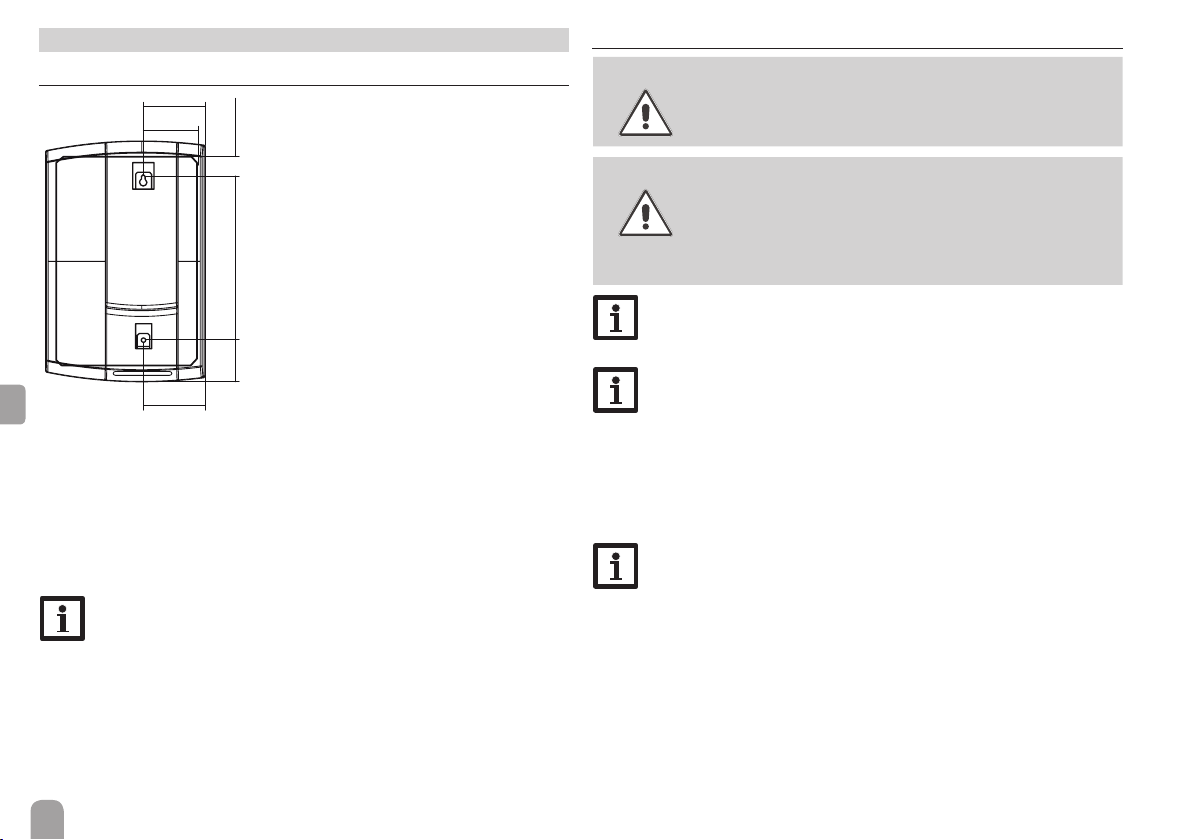
Resol FlowSol E User manual

FlowSol®E
*11210068*
11210068
Thank you for buying this RESOL product.
Please read this manual carefully to get the best performance from this unit.
Please keep this manual safe.
Manual for the
specialised craftsman
Installation
Operation
Commissioning
en
Manual
www.resol.com

2
en
Safety advice
Please pay attention to the following safety advice in order to avoid danger and
damage to people and property.
Instructions
Attention must be paid to the valid local standards, regulations and directives!
Information about the product
Proper usage
The electrothermal station is used for instantaneous water heating by means of
an electric heater in compliance with the technical data limit values in this manual.
Due to its design the station must be mounted and operated as described in these
instructions!
CE-Declaration of conformity
The product complies with the relevant directives and is therefore la-
belled with the CE mark.The Declaration of Conformity is available upon
request, please contact the manufacturer.
Target group
These instructions are exclusively addressed to authorised skilled personnel. Only
qualied electricians should carry out electrical works. Initial installation must be
effected by the system owner or qualied personnel named by the system owner.
Description of symbols
WARNING! Warnings are indicated with a warning triangle!
ÎThey contain information on how to avoid the
danger described.
Signal words describe the danger that may occur, when it is not avoided.
• WARNING means that injury, possibly life-threatening injury, can occur.
• ATTENTION means that damage to the appliance can occur.
Note
Notes are indicated with an information symbol.
ÎArrows indicate instruction steps that should be carried out.
Disposal
• Dispose of the packaging in an environmentally sound manner.
• At the end of its working life, the product must not be disposed of as urban
waste. Old appliances must be disposed of by an authorised body in an environ-
mentally sound manner. Upon request we will take back your old appliances
bought from us and guarantee an environmentally sound disposal of the devices.
© 20200124_11210068_FlowSol_E.monen

3
en
FlowSol®E
The RESOL FlowSol®E has been especially designed for using excess power
produced by a photovoltaic system.
The measuring device reliably detects excess current and the integrated controller
redirects it to a steplessly variable electric heater for heating a water store.
Thus, excess power can be stored as regenerative heat, internal consumption can
be increased while decreasing conventional heating costs.
Contents
1 Overview .............................................................................................. 4
1.1 System overview...........................................................................................................5
2 Mounting .............................................................................................. 6
2.1 Wall mounting...............................................................................................................6
2.2 Electrical connection ...................................................................................................6
2.3 Hydraulic connection buffer store (heating water)..............................................7
3 Commissioning.................................................................................... 8
3.1 Ball valve positions.......................................................................................................8
3.2 Venting the FlowSol®E...........................................................................................8
4 Non-return valve ................................................................................. 9
5 Maintenance......................................................................................... 9
6 Troubleshooting................................................................................... 9
7 List of spare parts.............................................................................. 10

4
en
1 Overview
• Integrated high-efciency pump and DeltaTherm®E controller
• Integrated electric heater of up to 3 kW, steplessly variable and grid compliant
• Retrottable in all heating and DHW systems
• Reliable household power priority
240400
212
212 76
76
605
Technical data
Circulating pump:
Wilo Yonos PARA 15/7.0-PWM2 (heating water)
(power consumption of the pump: 3…45 W)
Power supply: 220 … 240 V~ (50 … 60 Hz)
Cable cross section required: 2,5 mm²
Heating element: 0.8 kW / 0.8 kW / 1.4 kW
Nominal power / current: 0 … 3 kW (13 A)
Safety valve: 3 bar (heating water)
Connections: RP ¾'' IT
Admissible max. temperature: 95 °C
Maximum pressure: 3 bar (heating water)
Medium: Heating water
Dimensions: approx. 605 x 400 x 240 mm (incl. insulation)
Distance centre/wall: 76 mm
Weight: 14 kg
Material:
Fittings: brass
Seals: EPDM
Insulation: EPP foam
Pressure loss / pump characteristics
0
0
1
2
3
4
5
6
7
8
0,05 0,1 0,15 0,2 0,25 0,3 0,35 0,4
[mWs]
[m3/h]
Wilo
Yonos Para
15/7.0
FlowSol®E

5
en
1.1 System overview
Energy
meter
Controller
Measuring unit
Power unit
VBus®
Hydraulics Store Load
PV inverter
PV generator
VBus®

6
en
2 Mounting
2.1 Wall mounting
158
158
407103 50
134
ÎDetermine the mounting site of the station.
ÎDrill 2 holes (10 mm diameter, 407 mm centres) one below the other and
insert wall plugs.
ÎTighten the upper screw and washer, leaving the heat protruding (1 cm).
ÎHang the station from the fastening point, adjust with a level and attach with
the 2nd screw and washer.
ÎTighten both screws equally.
ÎConnect the pipework between the station and the store.
Note
All connections are already tightened such that they usually do not have
to be tightened again. However, during commissioning of the system all
connections have to be checked for leaks (pressure test).
2.2 Electrical connection
WARNING! Electric shock!
Upon opening the housing, live parts are exposed!
ÎAlways disconnect the device from power supply
before opening the housing!
ATTENTION! ESD damage!
Electrostatic discharge can lead to damage to electronic com-
ponents!
ÎTake care to discharge properly before touching
the inside of the device!To do so, touch a grounded
surface such as a radiator or tap!
Note
Connecting the device to the power supply must always be the last step
of the installation!
Note
It must be possible to disconnect the device from the mains at any time.
ÎInstall the mains plug such that it is accessible at any time.
ÎIf this is not possible, install a switch that can be accessed.
Do not use the device if it is visibly damaged!
This station is already pre-assembled and pre-connected.
ÎConnect the mains cables and establish the bus connection to the controller.
Note
For more information about the electrical connection, see controller
manual.
The station is supplied with power via a mains cable.The mains connection must
be carried out by means of the plug (delivered with the station) and a separate
2.5 mm² line.The power supply must be 220… 240 V~ (50…60 Hz).
Neutral conductor N
Conductor L
Protective conductor ⏚

7
en
ÎPut the cover on the plug.
The cover also serves as a strain relief.
ÎConnect the plug to the connector attached to the base plate.
Further loads such as washing machines must not be connected in paralel to the
station.
VBus®
N⏚L
Connector piece
Mains (16 A)
Screw terminal
VBus®
to measuring unit
DeltaTherm®E controller
DeltaTherm®E Power power unit
DeltaTherm®E Sensor measuring unit and current sensors
The bus cable can be extended with a two-wire cable (bell wire).The cable carries
low voltage and must not run together in a cable conduit with cables carrying a
higher voltage than 50 V (please pay attention to the valid local regulations.The
cross section must be at least 0.5 mm2and the cable can be extended up to 50 m
in the case of a single connection.
2.3 Hydraulic connection buffer store (heating water)
Flow
Return
VL
RL
Designation Description
FL Flow
RE Return

8
en
3 Commissioning
When the hydraulic system is lled and ready for operation, connect the power
unit to the mains.The controller has to be connected to the power unit (pre-con-
nected) and to the measuring unit by means of theVBus®.
ATTENTION! Damage by overheating!
Commissioning the station in a system ready for operation
which is not hydraulically lled can lead to damage caused by
overheating!
ÎBefore commissioning, ll the system with water and vent it.
ÎCheck the station for leaks and seal, if necessary.
ÎFill the heating water system (HW) with ltered (and treated) water only and
vent the system completely.
3.1 Ball valve positions
WARNING! Scald danger! Damage by overpressure!
When the ball valve is closed, too high pressure may occur in
the blocked-off line if it is heated.
ÎIn order to prevent scald danger and damage by
overpressure, make sure the blocked-off line is not
heated.
Ball valve in operating
position
Ball valve in service
position
Ball valve closed
3.2 Venting the FlowSol®E
ÎFill the system with water.
ÎPut the ball valve in the ow line to the service po-
sition (see gure).
ÎSwitch-on the circulating pump at 10% speed for
1 min.
ÎPut the ball valve in the ow into the operating po-
sition.

9
en
4 Non-return valve
The non-return valve is located above the pump in the return line.
5 Maintenance
In order to remove limescale, we recommend cleaning the heating element and the
throttle orice annually.
ATTENTION! Damage caused by improper cleaning uids!
Using cleaning uids not suited for high-grade steel, copper or
nickel can damage the heating element!
ÎUse cleaning uids according to the manufacturer’s
instructions only.
For the cleaning uid, use chloride-free or low-chloride water
with low hardness.
Cleaning the heating element
In order to clean the heating element, carry out the following steps:
ÎRemove the heating element.
ÎFlush the heating element with appropriate cleaning uid against the normal
ow direction.
ÎFlush the cleaned heating element and the system with clear water.
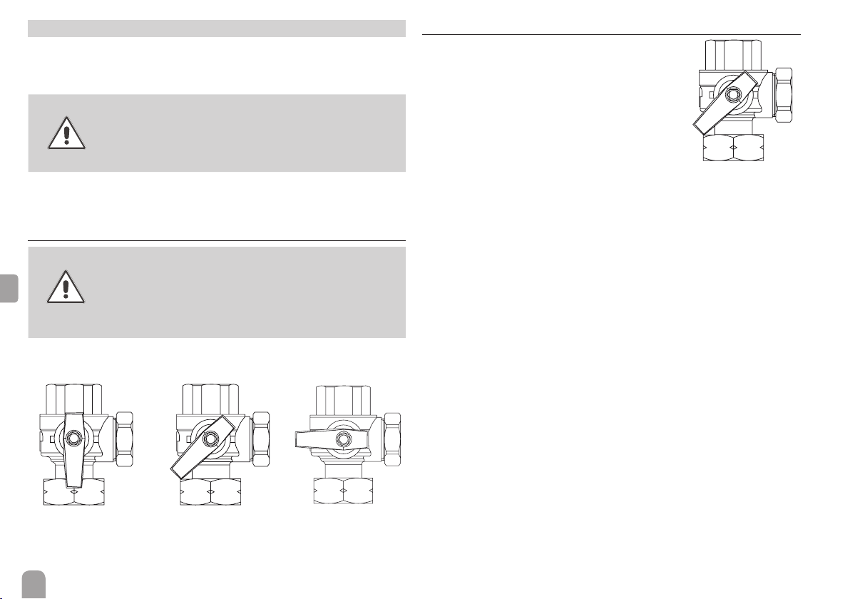
Cleaning the throttle orice
ÎIn order to clean the throttle orice, close both ball valves.
A B
ÎRemove the lateral cover (A) at the ball valve in the ow and clean the throttle
orice (B).
6 Troubleshooting
If an error has occurred, it will be indicated on the controller screen.
Please pay attention to the controller manual!
Fault condition Possible cause Elimination
Pump noise Air inside the system Vent the system
Flow rate too low
(ΔT too high)
Water pressure too low Check and increase pressure
if necessary
Heat exchanger calcied Decalcication / replacement
Throttle orice polluted Clean throttle orice, see
maintenance
Non-return valve blocked
(error message = red LED at
pump head)
Control pump at 10% speed
in manual operation
Target tempera-
ture not reached
Incorrect controller adjust-
ment
Check adjustments
Heating element
does not heat
Controller not in operation Check controller
Temperature sensor not cor-
rectly connected or defective
Check or replace, if necessary
Pump defective Check or replace, if necessary
Thermal cut-out triggered Reset (below black cover in
DeltaTherm®E Power)

10
en
7 List of spare parts
13 8910 11 12
1
2
3
4
5
6
7
14
Pos. Designation Spare part number
1 Wall plate -
2DeltaTherm®E Power (incl. thermal cut-out) 11209970
3 Cross piece with safety valve HW 11209948
4 Temperature sensor Store (S2) 11211397
5 Non-return valve see cross piece
6 Circulating pump HW 11209952
7 Return ball valve (RE) 11209953
8DeltaTherm®E 11209950
9 Heating element 11209956
10 Thermal cut-out 11211398
11 Temperature sensor (S1) 11211399
12 Flow ball valve (FL) 11209959
13 Insulation 11209961
14 Sensor module DeltaTherm®E sensor incl.
current sensors
11209960
Spare fuses FlowSol®E 29003090

11
en

Important note
The texts and drawings in this manual are correct to the best of our knowledge.As
faults can never be excluded, please note:
Your own calculations and plans, under consideration of the current standards and
directions should only be basis for your projects.We do not offer a guarantee for
the completeness of the drawings and texts of this manual - they only represent
some examples.They can only be used at your own risk. No liability is assumed for
incorrect, incomplete or false information and / or the resulting damages.
Note
The design and the specications can be changed without notice.
The illustrations may differ from the original product.
Imprint
This mounting- and operation manual including all parts is copyrighted. Another
use outside the copyright requires the approval of RESOL – Elektronische Rege-
lungen GmbH. This especially applies for copies, translations, micro lms and the
storage into electronic systems.
© RESOL – Elektronische Regelungen GmbH
Distributed by: RESOL – Elektronische Regelungen GmbH
Heiskampstraße 10
45527 Hattingen / Germany
Tel.: +49 (0) 23 24 / 96 48 - 0
Fax: +49 (0) 23 24 / 96 48 - 755
www.resol.com
Table of contents
Other Resol Inverter manuals
Popular Inverter manuals by other brands

Mitsubishi Electric
Mitsubishi Electric FR-A7AP instruction manual

ABB
ABB PVI-6.0-TL-OUTD Quick installation guide

Fortress Power
Fortress Power Sol-Ark LFP Legacy Series Guide

Mitsubishi Electric
Mitsubishi Electric FR-A5AP instruction manual

SMA
SMA SUNNY BOY 3600TL user manual

Smarter
Smarter ST-GP9750EB owner's manual