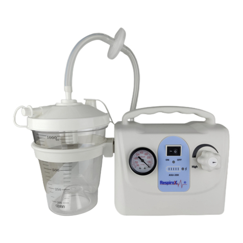
Respirox SS-6A User manual

Instructions on PortableAbsorb Phlegm
Apparatus SS-6A

3OHDVHFDUHIXOO\UHDGWKHLQVWUXFWLRQVEHIRUHDWWHPSWLQJWRRSHUDWHWKLVDSSDUDWXV
ProductFeatures
1. General
3RUWDEOH SKOHJP DSSDUDWXV 66$ GHVLJQHG EDVHG RQ GHYHORSLQJ RULHQWDWLRQ RI VLPLODU SURGXFWV DW KRPH DQG DEURDG
LV DQHZ JHQHUDWLRQ RI RLO IUHH OXEULFDWLRQ VXFWLRQ GHYLFH ZKLFK LV VXLWDEOH IRU XVH E\ WKH SDWLHQW ZKR KDV GLIILFXOW\
LQ SKOHJP UHPRYDO GXH WR LOOQHVV FRPD DQG RSHUDWLRQ DV ZHOO DV IRU DVSLUDWLQJ VXFK OLTXLG DV SXV DQG EORRG GXULQJ
WKH FOLQLFDO SUDFWLFH ,W LV WKH FRPPRQO\ DSSOLHG PHGLFDO GHYLFH IRU XVH LQ WKH HPHUJHQF\ URRP RSHUDWLRQ URRP
DQG IRU QXUVLQJ LQ VLFNURRP DQG KRPH KHDOWKFDUH
2. Structure &Working Principle
•2LOIUHHOXEULFDWLRQSXPSDSSOLHGWRNHHSWKHHQYLURQPHQWIURPEHLQJSROOXWHGE\WKHRLO PLVW
•/RZHU QRLVH
•1HZVW\OHRIWKHHPEHGGHGOLTXLGKROGHUVTXDUHQHJDWLYHSUHVVXUHPHWHUDQGIXOOSODVWLF HQFORVXUH
•1RDQ\SRVLWLYHSUHVVXUHWREHJHQHUDWHGGXULQJUXQQLQJWRHQVXUHUHOLDEOHDQGVDIH RSHUDWLRQ
•1HJDWLYHSUHVVXUHUHJXODWLQJV\VWHPLQVWHSOHVVDGMXVWPHQWDV UHTXLUHG
•6XLWDEOHIRUILUVWDLGDQGRXWGRRUJRURXQGIRUPHGLFDOWUHDWPHQWEHFDXVHRILWVIHDWXUHVVXFKDVVPDOOYROXPH
OLJKWZHLJKWDQGHDV\WRFDUU\ DERXW
•6\VWHPDWLFGLDJUDPVKRZQDV IROORZV
6\VWHPDWLF'LDJUDP
(Exhaust outlet) (Suction inlet) (Silencer) (Vacuum pump) (Negative pressure regulating knob) (Overflow
valve) (To phlegm suction tube) (vacuum meter) (air filter) (liquid holder)

3. Main TechnicalPerformances
(1) Limit negative pressure:
(2) Negative pressure regulating range:
(3) Suctionrate:
(4) Noise:
(5) Liquidholder:
(6) Powersource:
(7) Inputpower:
(8) Fusetube:
(9) Weight:
(10) Overallsize:
•The aspirator is not suitable for use in the place with inflammable & explosive gas;
•Working system: short time running;
•Electric safety requirement: Class I, Type Bequipment
4. Normal Operating Conditions
•Ambienttemperature: 5 ~40C
•Relativehumidity:
•Atmosphericpressure: 86 ~ 106 Kpa
•Installing andCommissioning
1. Open Package Inspection
The customer shall carefully inspect if the appearance of product is good, and the varieties &quantities of the
attachments are in conformity with ttube as indicated in the attached list before installing and commissioning.Also,
the customer shall timely notify the supplier or manufacturer of damage(s) ifany;
2. Connecting (See Tube Connecting Diagram, with phlegm suction tube temporarily not connected)
Note 1: Apply small amount of distilled water around the part (pressed into the holder mouth) of holder plug
during installing, which is good for tightly pressing the holder plug and enhancing its sealing.
(Suction tube) (Air filter) (Blue mark) (Suction conductor) (Liquid
Drawing: Tube Connecting Diagram
holder) (To the phlegm suction tube)
0.075 Mpa;
0.02 Mpa ~ limit negative pressure
ı15L/min(SS-6A)
İ65dB (A)
1000 ml/pc, 1pc
AC 220 V ±22V, 50Hz±1Hz
90 VA
RF1 Ï5X20/1.5A
5 kg
280 x 196 x 285(mm)
İ80%

4. Connectorinspection
•Turn tightly the negative pressure regulating valve clockwise, and block the air suction inlet with the
finger or the rubber head of dropper, or fold up and hold the suction tube;
•Start the aspirator for running with no strange sound; the pointer on the vacuum meter will quickly
reach up to the limit negative pressure. Release the suction inlet, the pointer will return below 0.02
Mpa. If so, the connector can be regarded as being in goodconnection.
•Attach the phlegm suction tube. The negative pressure in the negative pressure system shall be less than
0.06 Mpa at the time of attaching F6 suction tube, less than 0.04 Mpa when attaching F8 suction tube
and less than 0.03 Mpa when attaching F12 suction tube. If so, the phlegm aspirator is considered as
being in normal condition.
Note: Dredge the suction tube if blocked as per the following method: Bend the suction conductor in
“V” form (with no liquid in the holder), and release it to the original status when the negative
pressure reaches up to the maximum value. Repeat this procedure several times till the tube is not
blocked.
5. Negative pressure regulating
Block the suction inlet, open the aspirator switch and regulate the negative pressure valve, and the readings on the
pressure meter shall be within 0.02 Mpa ~ limit negative pressure.
•Control the negative pressure as required for suction by means of the negative pressure valve at the time of
clinicalpractice;
•Increase the negative pressure by turning the valve clockwise;
•Reduce the negative pressure below 0.02 Mpa prior to power shut-off.
3. Power lineconnection
Connect the plug with the power source. Turn on the power supply, and the power indicator will illuminate.
Note: The power plug is used for power shut-off, and the power socket shall be grounded reliably.
6. Inspection & test on the overflow device
•Open theholder plug;clean up the valve mouth, and leveling the rubber valve clack on the float.The valve
clack shall not be warped, bent and broken, but well connected with the float.The float shall be able to move
freely in its support without any blockage;
•Lift theholder plug with hand to make the float contact the water surface perpendicularly.Gradually lower
the holder cover to let the float rise;
•Tighten thehold plug, attach the suction tube conductor at the inlet, and screw firmly the regulating valve,
then, actuate the aspirator;
•Put the suction conductor into one clean water pail or attempt to simulate actual application to suction the
liquid into the holder of the overflow device.As aresult, the float will rise as the liquid level ascends until the
valve is closed and suction stops automatically.The final position of liquid level depends on the suction
process adopted;
•Release the regulating valve, set the aspirator switch off, open the holder plug and empty the liquid in the
holder.The float shall be at the bottom of the support and the valve is in open status in case of re-screwing
firmly the holdplug;
If so, the overflow device is considered as being in normal condition, which can be used for clinical practice.

Note:
1. The liquid level still continuously ascends after the overflow device has been shut off, possibly due to:
(1) Residual negative pressure still in the holder;
(2) Valve mouth not fully closed.
For Item (1), the liquid level in the holder will not ascend when the suction tube conductor is placed again
into the liquid as suctioned, and for Item (2), the liquid level still ascends.Thus, it is required to observe
carefully, and lift immediately the conductor out of the suctioned liquid when the holder is close to full, then,
switch off the aspirator to stop suction, and examine the possible reason of the valve fault.
2. The float is still adhered on the valve mouth as already closed by the float, possibly due to the negative
pressure in the line.At this moment, release the regulating valve or shut off the aspirator (to release the
negative pressure in the line), the float will descends from the valve mouth under the action of gravity. (It is
forbidden to pull the float with hand, in order to avoid the rubber valve clack being separated from the float);
3. After shut-off, release the negative pressure, then, open the holder plug;
4. Never use the aspirator under the condition of the overflow device & the conductor dismantled.
7. Stoprunning
Turn off the aspirator switch, and pull the power plug out of the socket to shut off the power supply.
8. Legends & implication for the sake of safety
Symbol Meaning Symbol Meaning
~AC power Note! Refer to the document on
board
Protection, earthing B type equipment
Application andMaintenance
1. Application &maintenance
•Check the aspirator before using as per the installing and commissioning sequence to ensure its good
performances, afterwards, start operation by connecting the suction conductor and the phlegm suction tube
alreadysterilized;
Note: Please refer to the instructions before attempting to use the suction tube supplied with the
aspirator.
•Regulate the negative pressure as required for suction through the regulating valve, open/close the switch
based on the situation, and observe frequently the liquid level in the holder in the process of operation. Stop
suction if the liquid level in the holder ascends to the rated capacity (still applicable if slanting the aspirator
10º), and re-use it after empty and clean-up. Otherwise, the float will rise as the liquid level ascends till the
valve is closed and suctionstops automatically;
Note: Adopt the procedures mentioned in “Inspection & test on the overflow device”, if the liquid level
still ascends after the overflow device has been shut off.

•Emergency measures in the process of application:
--- Quickly loosen the negative pressure regulating knob to release the negative pressure if the suction tube is
blocked by strong phlegm and mucus, and start suction again after changing the suction tube;
--- Adopt the above method to loosen the negative pressure regulating knob if it is not easy to take out the
suction tube after completion of suction or the tube is adhered to human body tissue.
Note 1: Bend the tube in “V” form prior to starting suction, insert the tube into the location of existing
phlegm on the patient when the negative pressure reaches the desired range after start-up, then, recover
the tube to its original status. This will lead to quicker suctioneffect.
Note 2: The medical personnel shall select the proper suction tube according to the clinical
requirement.
Note 3: The aspirator shall be operated under the medical personnel’s instructions strictly according to
the scope of application and the operating sequence listed in the instruction manual. Please contact the
supplier or manufacturer if there is any question.
2. Changing air filter
It is required to change air filter with the one produced by us in case of foam or dusts fully accumulated in the air
filter, which leads to gradually darkening of the color of filter diaphragm and obviously reducing or even
disappearing of suction force at the inlet of tube while the negative pressure indicated on the vacuum meter climbs
up to 0.04 Mpa or more.
Note 1: The suction force will diminish or disappear, and the negative pressure ascend if the overflow device
is closed, and the tube blocked in the process of application. Please refer to “Trouble Shooting”.

Note 2: Necessary to frequently change air filter and destroy it centrally.
3. Changing the fuse tube
The fuse tube is mounted at the rear of the base. Switch off the power supply, and turn it counterclockwise and
open, then, start changing thetube.
4.Maintenance
•It is recommended to have the suction tube suctioned small amountof clean water for cleaning up the inner
wall;
•After use, empty the holder, clean up dirt on the holder and plug with soft brush or rag, flush it with water and
conduct sterilization. (including the overflow device, the seal ring and various tubes. Unscrew the overflow
device, and separate the float from its support for completely cleaning up, if necessary. (Note: The rubber
valve clack shall not be separated from the float.)
•Use the physiological saline to clean out the residual strong phlegm and mucus in the tube after used.
Replace the suction tube if not smooth. It is recommended to adopt one-time suction tube;
•Place the holder, cover and all tubes into the disinfectant compounded with the
Kangweida disinfector tablets (0.5 g per tablet) in 1:500 concentration for 1 hour
Note: Keep the glass holder away from any sharp utensils to avoid drop in the process of cleaning and
application.
•Wipe the case outer surface with lightly wet rag already soaked in the disinfectant, and prevent any liquid
seeping into the pump. Never wipe the places marked with letters and patterns;
•Place the machine in dry and clean places, and periodically start running once a time (normally one time
every 6 months).
Note: Install the overflow device, conductor and other tubes as per the connecting mode before
re-use.

5. Trouble shooting
No. Problem &
Question
Reason PossibleSolution Remarks
1Limit
negative
pressure <
0.075Mpa
a.Holder mouth leakage;
b.Leakage on connecting
points;
c.Regulating valve loose
orreleased.
a. Remove dirt, tighten or change the
holdercover, seal ring, and connector;
b. Re-tighten each connection point;
c. Turn tightly the regulatingvalve
b. Change the
broken suction
tube
2Negative
pressure >
0.04 Mpa,
with distinct
reduction or
disappearing
of suction
force at tube
outlet
a. Overflow device
shut-off;
b. Tubeblockage;
c. Air filterblockage
a.After shut-off, turn the regulating valve
loose counterclockwise to release
negative pressure in tube, then re-screw;
b. Dredge, clean or replace the tube;
c.Replace it with air filter produced by us.
a. Empty the
holdertimely;
c. The end (in
blue mark) of
air filter is the
airinlet
3Normal
power
voltage, but
the indicator
doesn’t
illuminate
a. Loosesocket;
b. Fusebroken;
c. Indicatordamaged
a. Repair or change the socket;
b. Replace the fuse tube;
c. Replace the indicator
b. Size: RF1 cp
5 X20/1.5A
4Fuse tube
broken
a. Voltage over high;
b. Internal line in fault;
C. Pump blocked, and
currentincreasing
a. Adjustvoltage;
b. Check the circuit line, and correct;
c. Check the pump body and motor
By the
specialized
maintenance
worker ( Refer
to Electric
Systematic
Diagram)
Note: The dismantling & repair on the pump body if fault shall be conducted by the specialized worker.
Please contact the manufacturer if required.

Precautions -Tedbirler
1. Handling and storage environment conditions
•Ambienttemperature:
•Relativehumidity:
•Atmosphericpressure: 500 ~ 1060hPa
Note: It is required to store the aspirator in the well-ventilated room without corrosive gas, and avoid any
violent shock whilehandling.
2. Electric systematicdiagram
: Electric repair to be conducted by the specialized operatorGrey Brown Blue
2. After-saleservice
•The manufacturer will be responsible for repairing or replacing free of charge this apparatus if it doesn’t work
properly under normal storage &operating conditions within 1.5 years starting from the ex-works date or 1
year from the sold date;
•Necessary information on the circuit diagram and for check is available upon request.Please contact the
manufacturer if there is any problem related to the circuit check.
4. Attachments
•Suction conductor (2m long):
•Air filter:
•Fuse tube (RF1 et>5X20/1.5A)
•Suction tube( SS-6A)
•Instruction manual:
•Product warrantycard:
•Certificate ofquality:
onepc
two
two sets
one pcrespectively
onepc
one copy
one copy
onecopy
-40 ~ 55ć
İ95%

Jiangsu Shuangsheng Medical Appliance Co., Ltd. Dandong Industrial
Park, Danyang City (No. 12 Lingkou 122 Highway Industrial Zone),
212353Danyang,P.R.China(96468)
ProlinxGmbH
Brehmstr. 56 40239, Düesseldorf GERMANY
Tel: 0049 2131 4051968-0 Fax: 0049 2131 4051968-9
İTHALATÇI: ECE TIBBİ CİHAZLAR VE MEDİKAL SAN. TİC. A.Ş
Sümer Mahallesi Prof. Dr. Turan Güneş Cad. The İstanbul Veliefendi
Sit. G1 Ticaret Apt. No: 57 AC Zeytinburnu –İstanbul -TÜRKİYE
MERKEZ: Sümer Mah. Prof. Dr. Turan Güneş Cad. No:
57/AC Zeytinburnu / İSTANBUL
TEKNİK SERVİS: Telsiz Mah. Balıklı Kazlıçeşme Yolu
Sok. No:29/A Zeytinburnu /İSTANBUL
SİRKECİ: Hocapaşa Mah. Ebussuud Cad. Telli Oğlu İş
Merkezi No:36/A Sirkeci –Fatih MALTEPE: Başıbüyük Mah. Başıbüyük Cad.
No:10/A-2 Maltepe / İSTANBUL
KARAGÜL: Molla Gürani Mah. Turgut Özal Millet Cad.
Karagül İş Merkezi No: 84/2B25 Fatih / İSTANBUL ANKARA: Bahçelievler Mah. Şevket Süreyya Aydemir
Sok. No:4/A Bahçelievler / ANKARA
CİBALİ: Zeyrek Mah. Atatürk Bulvarı 7/G
Fatih / İSTANBUL (SGK Cibali Binası Yanı) BURSA: Demirtaşpaşa Mah. 2. Sabunevi Sok.
No:32/A Osmangazi / BURSA
www.respiro .com.tr 444 78 96 www.ecemedikal.net
Table of contents
Other Respirox Medical Equipment manuals
Popular Medical Equipment manuals by other brands

BRASSELER USA
BRASSELER USA EZX instructions

Cochlear
Cochlear Baha Instructions for use

InMode
InMode InMode System with BodyFX Handpiece Operator's manual

Otto Bock
Otto Bock 2R119 Instructions for use

Fresenius Medical Care
Fresenius Medical Care 2008T BlueStar quick start guide

Albrecht
Albrecht CDS ANKLE BRACE User instructions