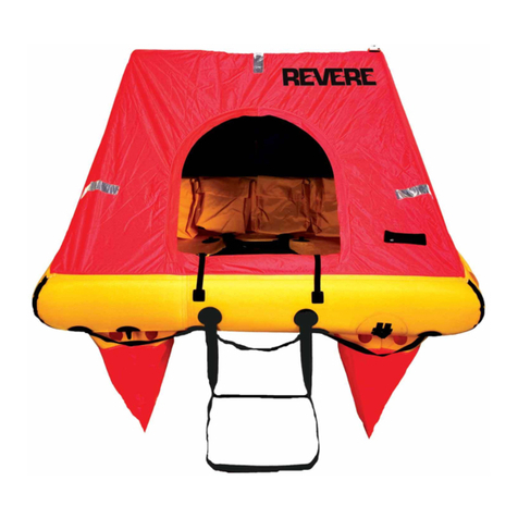
Revere Coastal Compact 2 User manual

SERVICE MANUAL
TITLE PAGE Page 1
Third Edition
Document No. 9102
5323 Highway Avenue
Jacksonville, FL 32254 USA
International (+001) 904 503 9733
Fax 904 503 9719
www.reveresurvival.com


REVISION RECORD
Jan 18/11
9102 RR - 1
RR
DOCUMENTING A REVISION
Record the Revision No. and Revision Date. Remove the old sheet and replace it with the revised copy.
Record the Insert Date and then initial in the Inserted By column.
Revisions made ONLY by Revere Supply, Inc.
REV. No. REV.
DATE INSERTED
REV. No. REV.
DATE INSERTED
DATE BY
DATE BY
Original June 2/08
A Jan 18/11

June 2/08
RR - 2 9102
THIS PAGE INTENTIONALLY LEFT BLANK

LETTER OF TRANSMITTAL
Revere Supply Co., Inc., Jacksonville, FL 32254
T. 904.786.0033 F. 904.786.0890
LT
To: Holders of Manual No. 9102
Title: Coastal Compact
Service Manual
Revision No.: B
Date: 05/2013
Signed: Date: 05/29/2013
Director of Technical Services
Pages Affected Pages: Added (A)
Replaced (RP)
Removed (RM) Revision Highlights
EFFECTIVE PAGES 1, 2, 3, 4
TABLE OF CONTENTS TC
-1
CHAPTER 1 1
-3
CHAPTER 2 2
-9
CHAPTER 3 3
-3, 3-5
CHAPTER 4 4
-3
4
-9
4
-10
4
-13
4
-15
4
-16, 4-17
CHAPTER 6 6
-5
CHAPTER 7 7
-3
7
-5, 7-6, 7-8
7
-9, 7-10
7
-12
7
-13
CHAPTER 8 8-3
RP
RP
RP
RP
RP
RP
RP
RP
RP
RP
RP
RP
RP
RP
RP
RP
RP
RP
Updated page dates
Added
Section 12
Added Spare Parts
Change
d graphic notation
Revised wording
Revised wording
Changed part number
Revised wording
Added part number
Changed part number
Revised wording
Revised wording
Revised wording
Changed part number
Revised wording
Changed image
Revised wording
Revised wording
RECORD THE INCORPORATION OF THIS REVISION ON THE REVISION RECORD.
RETAIN THIS LETTER OF TRANSMITTAL, FILE IT BEHIND THE REVISION RECORD.
LT - 1

LETTER OF TRANSMITTAL
Revere Supply Co., Inc., Jacksonville, FL 32254
T. 904.786.0033 F. 904.786.0890
LT
Pages Affected Pages: Added (A)
Replaced (RP)
Removed (RM) Revision Highlights
8-8
8
-9
8
-14
8
-18
8
-23
CHAPTER 9 9
-3
CHAPTER 10 10
-1
10
-3
10
-5, 10-6
10
-7, 10-8
CHAPTER 11 11
-1
11
-3, 11-7
11
-9, 11-10, 11-11, 11-12
11
-15, 11-16, 11-17, 11-18
11
-19, 11-20, 11-21, 11-22
11
-23, 11-24
11
-25, 11-26
11
-27, 11-28, 11-29, 11-30
CHAPTER 12
APPENDIX A A
-1
RP
RP
RP
RP
RP
RP
RP
RP
RP
RM
RP
RP
RP
RP
RP
RP
RP
A
A
RP
Changed image
Revised wording
Replaced lubricant type
Revised wording
Changed part numbers
Removed image list
Revised wording
Changed part numbers
Removed pages
Revised page numbers
Revised wording
Changed part numbers
Changed part nu
mbers
Changed part numbers
Changed images and part numbers
Added imagse and part numbers
Added Spare Parts section
Revised wording
RECORD THE INCORPORATION OF THIS REVISION ON THE REVISION RECORD.
RETAIN THIS LETTER OF TRANSMITTAL, FILE IT BEHIND THE REVISION RECORD.
LT - 2

LETTER OF TRANSMITTAL
RECORD THE INCORPORATION OF THIS REVISION ON THE REVISION RECORD.
RETAIN THIS LETTER OF TRANSMITTAL, FILE IT BEHIND THE REVISION RECORD.
Revere Supply Co., Inc., Jacksonville, FL 32254
T. 904.786.0033 F. 904.786.0890
LT
LT - 1
To: Holders of Manual No. 9102
Title: Coastal Compact
Service Manual
Revision No.: A
Date: 01/2011
Signed: Date: 02/18/11
Director of Technical Services
Pages Affected Pages: Added (A)
Replaced (RP)
Removed (RM) Revision Highlights
RECORD OF REVISION 1
EFFECTIVE PAGES 1, 2, 3, 4
TABLE OF CONTENTS TC-1
CHAPTER 2 2-4
2-5
2-6
2-7
2-10, 2-11, 2-12
2-13
2-14
2-15
2-16
CHAPTER 3 3-6, 3-7
3-8
CHAPTER 4 4-1
4-14
4-15
4-17
RP
RP
RP
RP
RP
RP
RP
RP
RP
RP
A
A
RP
RP
RP
RP
RP
RP
Added Revision A
Updated page dates
Added Appendix A
Added canopy illustration
Added canopy description
Revised knife description
Added canopy description
Updated Table A, Added Table B and Fig. 4 Illustration
Added canopy operation proceedures
Fig. 4 became Fig. 5. Changed knife illustration
Added page to show Fig. 6, canopy illustration
Added blank page
Added Figure note
Revised Fig. 4 to show canopy kit
Added Arch-tube to leakage test procedures
Added Archi-tube inflation procedures and Fig. 2
Logo change
Revised wording to include 6 person rafts

LETTER OF TRANSMITTAL
RECORD THE INCORPORATION OF THIS REVISION ON THE REVISION RECORD.
RETAIN THIS LETTER OF TRANSMITTAL, FILE IT BEHIND THE REVISION RECORD.
Revere Supply Co., Inc., Jacksonville, FL 32254
T. 904.786.0033 F. 904.786.0890
LT
LT - 2
Pages Affected Pages: Added (A)
Replaced (RP)
Removed (RM) Revision Highlights
CHAPTER 7 7-1, 7-10
CHAPTER 8 8-1
8-5
8-6
8-7, 8-8
8-10
8-20
8-23, 8-24
8-26
8-33 THROUGH 8-40
8-41 THROUGH 8-48
8-49
8-50 THROUGH 8-52
CHAPTER 11 11-1
11-9, 11-10
11-12
11-13, 11-14, 11-15
11-16, 11-17
11-18, 11-19
11-20, 11-21
11-22
11-23
11-24
11-25
11-26
APPENDIX A
RP
RP
RP
RP
RP
RP
RP
RP
RP
RP
A
A
A
RP
RP
RP
RP
RP
RP
RP
RP
RP
RP
RP
RP
A
Added canopy to component repair
Added canopy to component setup
Clarified length of cord used for light attachment
Added canopy folding instructions
Adjusted figure positions
Added torque setting to Table A
Added CC6 to Table B
Updated procedure with canopy instructions, Added
Table D
Added canopy kit illustration
Revised CC4 folding illustations to include canopy kit
Added CC6 folding illustrations
Figure 9 revised to show canopy kit storage
Adjusted figure positions
Changed page number of Image List
Updated list to include new part numbers
Updated Fig. 1 to show canopy
Updated item list to include canopy components and CC6
Adjusted Fig. 2 position. Updated item list to include CC6
components
Adjusted Fig. 3 position. Update item list to include CC6
components
Adjusted Fig. 4 and item list position
Added Fig. 5
Adjusted page number Image List begins.
Changed knife image, removed knife sheath
Added key ring image
Added canopy buckle strap
Added Appendix A

SERVICE BULLETIN
June 2/08
9102 SB - 1
SB
All service bulletins which are incorporated into this manual are required to be recorded in this list.
All updates to this list will be made by the owner of the manual.
SERVICE
BULLETIN No. DATE TITLE/DESCRIPTION REV. No. DATE OF
INCORPORATION

June 2/08
SB - 2 9102
THIS PAGE INTENTIONALLY LEFT BLANK

SERVICE BULLETIN NO. 09/16
Sept 20/16
9102SB - 1
5323 Highway Avenue
Jacksonville, FL 32254
(T) 904.503.9733
(F) 904.503.9719
1. INTRODUCTION
This service bulletin is to advise service stations of the change in valves, firing heads and cylinders
for the Coastal Compact liferafts.
Starting from July, 2014 all Coastal Compact rafts produced by Revere will now be equipped with
the following valves
Pressure Relief Valve: Thanner OTS-45 (Revere P/N 95-324-004)
Topping Off Valve: Mirada A-52030 (Revere P/N 95-326-009)
Inlet Check Valve: Mirada B-51994 (Revere P/N 95-325-005) 3/8-18NPSM
Universal Flange (PU): Mirada B-51073 (Revere P/N 95-326-001)
As a result of the inlet check valve replacement, new firing heads and cylinders are required for all
rafts starting in July 2014.
For the Coastal Compact 2 person, two additional cylinders updates occurred. One in 2015 and
the most recent in September of 2016.
Raft Number
Firing Head
Cylinder
Coastal Compact 2 (45-CC2V)
95-41115-103
(Circor M70 w/ 3/8-18 NPSM)
95-327-061 (61in3) Re-fillable
[2015: 95-323-440
(440g disposable)]
Coastal Compact 4 (45-CC4V)
95-43012-101
(Thanner DK-99S)
95-43013-101 Cylinder Adaptor
95-327-061 (61in3) Re-fillable
Coastal Compact 6 (45-CC6V)
95-43012-101
(Thanner DK-99S)
95-43013-101 Cylinder Adaptor
95-327-103 (102.5 in3)
Re-fillable
The purpose of the technical update is to show the items and procedures to follow for the
servicing of the inflation system and recharging of the cylinders with current valves and firing
heads.
2. EMBODIMENT DATE
Mandatory at next service.

SERVICE BULLETIN NO. 09/16
Sept 20/16
9102SB - 2
5323 Highway Avenue
Jacksonville, FL 32254
(T) 904.503.9733
(F) 904.503.9719
3. VALVE IDENTIFICATION
Thanner OTS-45 Mirada A-52030 Mirada B-51994
4. FIRING HEAD 95-41115-103 (M70) OPERATING INSTRUCTIONS
See Chapter 8 –Assembly and Packing, Inflation Valve Disassembly & Rebuilding Process for
instructions on servicing the 41115 inflation valve. All service instructions remain the same, but
note the outlet fitting is now 3/8-18 NPSM rather than the previous fitting of 1/2-20 UNF.
3/8-18 NPSM

SERVICE BULLETIN NO. 09/16
Sept 20/16
9102SB - 3
5323 Highway Avenue
Jacksonville, FL 32254
(T) 904.503.9733
(F) 904.503.9719
5. 95-43013-101 CYLINDER ADAPTOR FOR THANNER DK-99S OPERATING HEAD
DISASSEMBLY, REPAIR, AND REASSEMBLY
The following instructions are copied from Thanner QA doc. No. 2057
The adaptors are part of the THANNER inflation systems for life rafts and constructed for marine
and aviation use. The valve is made of brass and nickel plated. It is machined to accommodate a
diaphragm holder having a combined safety and penetration disc function. The diaphragm holders
are replaceable. The cylinder adaptor/valve fits the DK 99S. The newer versions of the valves
have the syphon tube permanently attached to the valve and if the attachment of the siphon tube
is loose and falls off the complete assembly must be replaced. Older versions of the syphon tube
can be re-attached.
Lifetime: 10 years after installation. Can be extended if the valves are in good condition. Product
and legal Warranty: 1 year after purchase.
CAUTION:
Under no circumstances the cylinder valve must be removed from the cylinder except by
competent and trained personnel of an authorized service station.
NOTICE:
The work bench must be clean and dry and well-arranged.
WARNING:
The charged cylinder must be discharged only if the filling head (90-029)
with the membrane key has been fitted on the top of the valve and
tightened by hand. The cylinder and filling set must be carefully placed in a
vice bench and with the outlet away from the operator. As the membrane
key is turned counter-clockwise, the gas will start to discharge though the
outlet. It is very important the cylinder is safely kept by the vice bench.
90-029

SERVICE BULLETIN NO. 09/16
Sept 20/16
9102SB - 4
5323 Highway Avenue
Jacksonville, FL 32254
(T) 904.503.9733
(F) 904.503.9719
REMOVE THE CYLINDER VALVE:
Remove the cylinder valve using a 30mm spanner tool. Use suitable spanners only, to avoid
damage of the valves.
With the cylinder completely discharged and clamped firmly to the vice bench, remove the filling
head. With tool 005-657 unscrew and remove the diaphragm holder from the valve.
REMOVE THE ADAPTOR:
Use THANNER tool 99-120. This tool 99-120 can only be used when the diaphragm holder is
removed from the valve. If you have any questions or doubt about the right procedure using the
tool 99-120, please contact us. Use suitable spanners only, to avoid damage of the valves.
Unscrew the adaptor counter-clockwise and inspect the valve and siphon tube. It is essential the
tool 99-120 is placed correctly in the adaptor so as not to cause any damage.
Incorrect Correct
The removed diaphragm holder cannot be used again.
CLEANING:
Clean all the parts with air.
Remove the P.T.F.E. from the valve and cylinder threads. Check the threads and bores are free
from nicks or burs. Check the diaphragm seat is clean and no signs of visible damage. If the
diaphragm seat is damaged -replace the valve.
ASSEMBLY:
Older versions of the valve have a screwed in siphon tube. Refit it and use a torque spanner.
Torque: 15 Nm. Do not use P.T.F.E. tape with the siphon tube!
Apply P.T.F.E. tape to the valve thread and screw the valve into the cylinder. Place the cylinder in
a vice. Screw the valve in with your hand and use a torque spanner (99-120) to torque the valve.
For connection to aluminum cylinders, Torque: 54-61 Nm = 40-45 foot pound, using P.T.F.E.

SERVICE BULLETIN NO. 09/16
Sept 20/16
9102SB - 5
5323 Highway Avenue
Jacksonville, FL 32254
(T) 904.503.9733
(F) 904.503.9719
IMPORTANT:
To tighten or loosen the DK99S adaptor it is essential to use the tool 99-120.
Place the new diaphragm holder into the valve and screw the holder carefully into the valve with
your finger. The diaphragm holder must be kept loose before filling cylinder. Fit an aluminum
transport cap on the top of the valve.
ASSESSORIES:
1. Tool for diaphragm holder 005-657
2. Spanner for the adapter size 30mm Commercial
3. Top spanner for adaptor DK-99S system 99-120
4. Filling tool for DK 94/99 system CO2 90-029
5. Seal kit DK 94/99 filling heads 90-029 pos. 2&5
6. Transport protection cap for DK94/99 system 90-039
6. CHARGING THE CYLINDER WITH DK-992
Thanner cylinder valves/adapters for CO2 to a maximum working pressure of 250 Bar.
Thanner cylinder valves/adapters for N-2 or Air to a maximum working pressure of 300 Bar.
CHARGING OF THE CYLINDER
WARNING: Due to low gas temperatures -always use gloves.
NOTE 1:
All the threads are normally handed, this means turning clockwise tightens and turning
counter-clockwise untighten. Please refer to the relevant life raft manufacturer's service manual
for charging regulations.
NOTE 2:
Theoretical Tare weight and full charge weight are marked on the cylinder. Actual weight of the
assembly will appear on the cylinder data label. Check tare weight.
Connect the filling hose to the Cylinder valve Outlet: See Illustration. Do not allow the cylinder to
hang from the filling line. Secure the cylinder in the vertical position with the adapter up.

SERVICE BULLETIN NO. 09/16
Sept 20/16
9102SB - 6
5323 Highway Avenue
Jacksonville, FL 32254
(T) 904.503.9733
(F) 904.503.9719
NOTE 3:
Inspect the condition of the filling tool and the 0-rings. If damaged, replace the o-rings (see page
3). It is important the O-rings are not warn or compressed. If damaged it will reduce opening of
the diaphragm holder and through, the charging facilities as well. Fit the filling head onto the
cylinder valve/adapter and tighten up the filling head by hand or with an open spanner size 50
mm. Requested torque: 8 Nm = 6 foot pound.
With a small spanner, turn the diaphragm assembly open, i.e. turn counter-clockwise before
charging the cylinder. An "elastic" reaction will be felt when the diaphragm assembly is correctly
open (this "elastic" reaction is caused by compression of the 0-ring within the filling head).
IMPORTANT:
The membrane must be fully open.
If not the membrane can be to warm and the risk for overheating can dome the disc
NOTE 4:
The charge weight does not include filling head-Membrane only!
Make allowance for this when checking gross weight.
NOTE: The start pressure must not exceed 30 bar= 430 psi
Via the gas charging equipment, charge the cylinder with the appropriate quantity of carbon
dioxide until the specified cylinder charge condition is reached.
Raft
CO2
Coastal Compact 4
1.44 –1.5 lbs.
Coastal Compact 6
2.44 –2.5 lbs.
Close the diaphragm holder tight against the seat to a torque of app. 40-50 Nm = 29-36 foot
pound until it's tight.

SERVICE BULLETIN NO. 09/16
Sept 20/16
9102SB - 7
5323 Highway Avenue
Jacksonville, FL 32254
(T) 904.503.9733
(F) 904.503.9719
Close off charging gas supplies to the filling head. Depressurize the filling head by carefully
releasing the charging hose connection. Remove the charging hose from the filling head and
remove the filling head from the adapter by hand.
CAUTION:
Ensure filling head and charging hose are completely depressurized before complete
Disconnection. Check the charged valve/adapter and diaphragm holder for leaks, using a small
quantity of alcohol covering the diaphragm holder. If leaking, tiny bubbles will appear.
Use technical alcohol with at least 75% alcohol only.
NOTE: If leaking, re-tighten the diaphragm holder until it is tight. Torque: 40 -50 Nm = 29-36
foot-pound.
Retest the diaphragm holder with alcohol.
NOTE: DO NOT USE WATER or WATER BASED DETECTIVE!
If still leaking discharge the cylinder, remove and dispose the diaphragm holder and replace it.
Repeat the charging procedure as described.
After testing remove the alcohol and fit the transport protection cap.
Do not separate the diaphragm holder before use.
Important information for the charging personnel
A. Record weight on cylinder label
B. Record date of charging
C. Record I.D. specification of the operator
STORAGE INSTRUCTIONS:
Conditions: Store in a cold, dry atmosphere, free of corrosive fumes with the protection cap
fitted.
Limited Periods: Newly charged cylinders MUST be checked after min.14 days
CAUTION: Do not handle or store the charged cylinders without metal protection.
Do not use plastic caps!

SERVICE BULLETIN NO. 09/16
Sept 20/16
9102SB - 8
5323 Highway Avenue
Jacksonville, FL 32254
(T) 904.503.9733
(F) 904.503.9719
SPECIAL TOOLS, FIXTURES AND MATERIALS:
The following are required during filling:
Aluminum protection cap
Filling tool complete.
Tool for diaphragm holder
Spare diaphragm holders
TBA Permanite GT P.F.T.E,
Technical alcohol
SCHEDULE OF OVERHAUL PERIODS:
Adapter: On condition or maximum 5 years.
ACCESSORIES:
1. Tool for diaphragm holder 005-657
2. Spanner for the adapter size 36/30 Commercial
3. Open spanner size 50 Commercial
4. Filling head DK 94/99 system CO2 90-029
5. Seal kit DK 94/99 filling heads 90-029 pos. 2&5
6. Transport protection cap for DK94/99 system 90-039
7. Technical alcohol in 2.5 or 10 liter canister Commercial
CHARGING PROCEDURE
To ensure correct and equal charging and to protect the diaphragm against overload during
charging, the following procedure should be followed.
When starting charging, there is no pressure in the cylinder, i.e. under the diaphragm, but there is
a possibility of high pressure on top of the diaphragm.
The diaphragm holder can withstand a certain difference in pressure (Pressure drop) across it,
without getting damaged.
Damaged in this case means the diaphragm itself will dome downwards under influence of the
pressure on the topside. If the pressure is too high the doming can crack the seal ring or blow off
the diaphragm, which will create leak problems. This is particularly relevant for high pressure Air
filled bottles.

SERVICE BULLETIN NO. 09/16
Sept 20/16
9102SB - 9
5323 Highway Avenue
Jacksonville, FL 32254
(T) 904.503.9733
(F) 904.503.9719
NOTE: The filling temperature must not exceed +65°C.
Higher temperature will cause a higher dome of the membrane disc!
The pressure difference across the diaphragm holder during charging should not exceed 30
bar = 430 psi.
This means the flow of gas shall be controlled continuously, starting slowly to build up the
cylinder pressure.
RECOMMENDED PROCEDURE:
1. Prepare the cylinder for charging, i.e. protection cap is removed, check the adapter is clean
inside and insert the diaphragm holder by hand
2. Weigh the empty cylinder, i.e. the cylinder with the diaphragm holder and write the weight
onto the label.
3. Charge CO2until the correct weight and write the weight on the cylinder label
4. The charged cylinder is disconnected from the charging connection and is weighed again.
Write the total weight on the cylinder label. The operator signs and dates the label.
5. The diaphragm holder is tightened by means of a torque spanner to a torque of approx. 40-
50Nm (29-36 foot pounds).
6. The gas tightness must be checked by pouring a small amount of alcohol over the
diaphragm holder while the cylinder is vertical. No bubbles must be seen.
7. The protection cap must now be fitted.
HOW TO USE THE SETUP:
When the diaphragm holder has been opened in accordance to the manual to allow charging,
valve position 1 is slowly opened until the pressure, indicated on gauge position 2, raises to a
maximum of app. 30 bar= 430 Psi. Listen to the flow noise. When it stops or reduces, you can
gradually open more and in this way keep the charging running until fully charged.
If you have to disconnect when changing to another gas, you can follow two procedures using
two different set ups:
Set up 1. Valve pos. 1 and gauge pos. 2
Close the diaphragm holder and valve # 1. Disconnect from one gas to another gas supply, open
for the supply, open the diaphragm holder and watch the pressure on gauge pas. 2. Slowly open
valve pas. 1 and raise the pressure to a maximum of 30 bar = 430 psi above the cylinder pressure
or until the charging weight is obtained. Close the diaphragm holder according to the manual.
Set up 2. Valve pos. 1 & 3 and gauge pos. 2.
The setup has an extra valve pos. 3, which is closed instead of the diaphragm holder and the
cylinder pressure will remain visible on the gauge while changing. This set up will save the seal
ring of the diaphragm holder for extra operations.

SERVICE BULLETIN NO. 09/16
Sept 20/16
9102SB - 10
5323 Highway Avenue
Jacksonville, FL 32254
(T) 904.503.9733
(F) 904.503.9719
IMPORTANT!
No matter what kind of charging set up is used, it is important the process starts
slowly to avoid pressure choke!
IMPORTANT!
During the charging procedure the temperature in the cylinder valve/filling head must not exceed
+65° C. Overheating will damage the disc and increase the dome, which can cause penetration of
the disc.
IMPORTANT!
Over charging in relation to above will create risk of premature inflation at +65 degrees C
Thanner QA 0110 shows data of different Thanner diaphragm holders
This manual suits for next models
5
Table of contents
Other Revere Marine Safety Device manuals