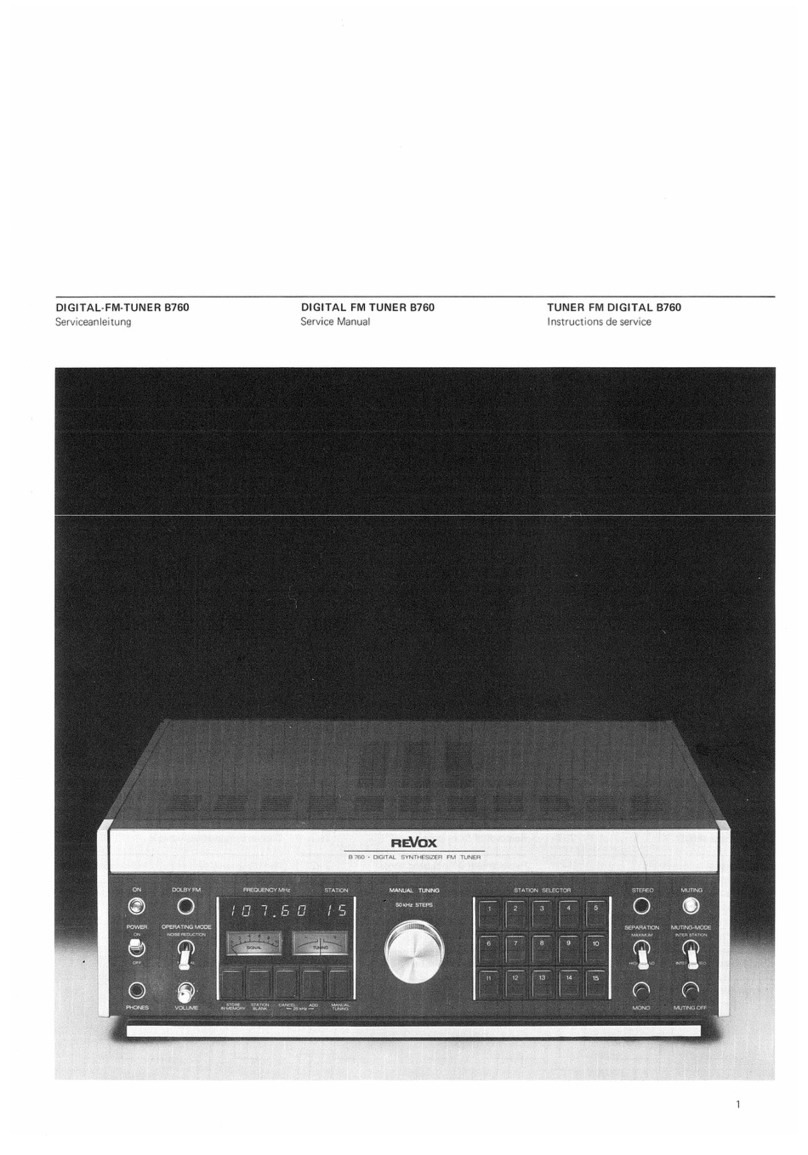
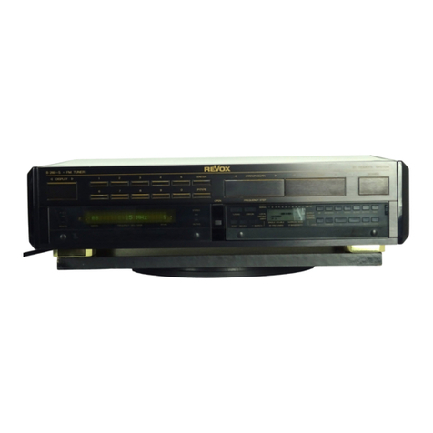
Revox B760 User manual

DIGITAL-FM-TUNER B760
Serviceanleitung
DIGITAL mTUNER B760
Service Manual
TUNER mDIGITAL B760
Instructions de service

INHALTSVERZEICHNIS
Bezeichnung Seite
1.
Allgemeines 1-1
Einschalten/Abstimmen 1-1
Bedienung fur Stationsspeicherung
und 25 kHz-Versatz
1-2
Funktion DOLBY, Pegelregler und
Ausgange
1-2
Anschiussfeld auf der RCickwand 1-3
Technische Daten 1-4
Abmessungen 1-7
2.
Ausbau 2-1
Entfernen des oberen Deckbleches 2-1
Entfernen des unteren Deckbleches 2-1
Entfernen der seitlichen Abdeckungen 2-1
Bedienungs-Einheit ausbauen 2-1
Frontplatte ausbauen 2-2
Anzeigelampen auswechsein 2-2
Lampe fur Instrumentenbeleuchtung
auswechsein
2-2
VU-Meter ausbauen 2-2
Netzsicherung auswechsein 2-3
Netzteil-Sicherungen auswechsein 2-3
CONTENTS
Description Page
1.
General 1-1
Switching on/station selection 1-1
How to operate the station memory
and the 25 kHz offset
1-2
DOLBY circuit, level control and
outputs
1-2
Connectors on the rear panel 1-3
Technical data 1-4
DiiTiensions 1-7
2.
Dismantling 2-1
Removal of top cover 2-1
Removal of bottom plate 2-1
Removal of side panels 2-1
Removal of operating section 2-1
Removal of front panel 2-2
Replacement of indicator lamps 2-2
Replacement of meter illumination 2-2
Removal of VU-meters 2-2
Replacement of main fuse 2-3
Replacement of secondary fuses 2-3
REPERTOIRE
Designation Page
1
Generaiites 1-1
ivlise sous tension/accord 1-1
Utilisation du selecteur de station a
memoire et du decalage de 25 kHz
1-2
Fonction DOLBY, reglage du niveau
et sorties
1-2
Panneau de raccordemient arriere 1-3
Caracteristiques techniques 1-4
Dimensions 1-7
2.
Demontage 2-1
Depose de la plaque de recouvrement 2-1
Depose de la plaque du fond 2-1
Depose des plaques laterales 2-1
Depose de I'unite de commande 2-1
Depose de la plaque frontale 2-2
Remplacement des lampes d'indicateurs 2-2
Remplacement des lampes d'eclairage
des instruments
2-2
Depose des instruments 2-2
Remplacement du fusible secteur 2-3
Remplacement des fusibles
d'alimentation
2-3
2

Bezeichnung Seite
3.
Funktionsbeschreibung 3-1
Obertrager 3-1
HF-Eingangsteil 3-1
ZF-Verstarker 3-1
FM-Demodulator 3-2
Stereo-Decoder 3-2
Lokal-Oszillator, Synthesizer 3-3
Abstimm-Einheit 3-4
Digitalteil 3-4
Logikteil 3-5
Audioteil 3-5
DOLBY® Decoder 3-6
Netzteil 3-6
4.
Abgieichanieitung 4^1
Messgerate 4-1
Zusatzliche Werkzeuge und Filter 4-1
Kontrolle der Speisespannungen 4-2
Vorbereitungen 4-^3
Abgleich des Lokal-Oszillators
und Synthesizers
4-^4
Abgleich HF-Kreise 4-5
Abgleich ZF-Filter, ZF-Verstarker
und Anzeige-Diskriminator
4-6
Abgleich Stereo-Decoder 4-8
Abgleich Signalstarke-I nstrument oT
Abgleich der NF-Ausgangsspannung 4-11
Description Page
3.
Circuit description 3-1
Antenna transformer (Baiun) 3-1
RF-section (front end) 3-1
1F-amplifier 3-1
FM-demodulator 3-2
Stereo decoder 3-2
Local oscillator, synthesizer 3-3
Tuning section 3-4
Digital section 3-4
Logic section 3-5
Audio section 3-5
Dolby decoder 3-6
Power supply 3-6
4.
Alignment instructions 4-^1
Test equipment 4-1
Additional tools and filters 4-1
Checking the supply voltages 4^2
Preparatory steps 4-3
Align men Lof local oscillator and
synthesizer
4-4
Alignment of RF-circuits 4-5
Alignment of 1F-filters, 1F-amplifier
and center tuning discriminator
4-6
Alignment of stereo decoder 4-8
Calibration of signal strength meter 4-10
Adjustment of audio output voltage 4-11
Designation Page
3.
Description des fonctions
Translateur 3-1
Etage d'entree F1F 3-1
Amplificateur FI 3-1
Demodulateur FM 3-2
Decodeur stereo 3-2
Oscillateur local, synthetiseur 3-3
Unite d'accord 3-4
Partie digitale 3-4
Partie logique 3-5
Partie audio 3-5
Decodeur Dolby 3-6
Alimentation 3-6
4.
Instructions de reglage 4^1
Appareils de mesure 4-1
Fibre et outillage special 4_^1
Verification des tensions d'alimentation 4-2
Preparations 4-3
Reglage de I'oscillateur local et du
synthetiseur
4-4
Reglage des circuits FIF 4-5
Reglage des fibres FI, de I'ampii-
ficateur FI et du discriminateur
4-6
Reglage du decodeur stereo 4^8
Reglage de I'indicateur SIGNAL 4-10
Reglage de la tension de sortie BF 4-11
3

Bezeichnung Seite
5.
Anieitung zur Messung der
wichtigsten technischen Daten
5-1
Eingangs-Empfindlichkeit b-1
Spiegel-Selektion 5-2
Nebenwellenunterdruckung b-3
Verzerrungen 5-4
Fremdspannungsabstand 5-4
Gbersprechdampfung 5-5
Frequenzgang 5-5
6.
Schaltungssammiung 6-1
7.
Ersatzteilliste 7—1
Description Page
5.
Instructions for measuring the most
important performance data
5-1
Input sensitivity 5-1
Image response 5-2
Spurious response b-3
Distortion 5-4
Signal to noise ratio 5-4
Stereo separation (crosstalk) 5-5
Frequency response 5-5
6.
Set of schematics 6-1
7.
Parts list 7—1
Designation Page
5.
Instructions pour la mesure des carac-
teristiques techniques importantes
5-1
Sensibiiite d'entree 5-1
Rejection image 5-2
Affaiblissement de I'intermodulation 5-3
Distorsion 5-4
Rapport signal/bruit 5-4
Affaiblissement de la diaphonie 5-5
Reponse en frequence 5-5
6.
Recueil des schemas 6-1
7.
Liste des pieces detachees 7—1
Anderungen vorbehalten. Subject to change. Sous reserve de modification.
Printed in Switzerland
by Wl LLI STUDER 18.183.1179 ED 2Noise reduction system manufactured under license Dolby Laboratories
Copyright by Willi Studer Dolby and the double-D symbol are trade marks of Dolby laboratories
CH-8105 Regensdorf-Zurich
4

1. Allgemeines 1. General 1. General ites
Einschalten/Abstimmen (manuell) Switching on/manual station selection Mise sous tension/accord (manuel)
©Netzschalter POWER, ON/OFF
(Ein/Aus) ©POWER switch ON/OFF ©Interrupteur secteur POWER, ON/OFF
(enclenche/declenche)
@Betriebsanzeige POWER (rot) ©Pilot light POWER (red) ©Indicateur de mise sous tension POWER
(rouge)
©Digitale Frequenzanzeige ©Digital frequency readout ©Affichage digital de frequence
©Abstimmknopf MANUAL TUNING ©MANUAL TUNING ©Selecteur d'accord manuel MANUAL
TUNING
©Absti mminstrument SIGNAL ®SIGNAL strength meter ©Indicateur d'intensite du SIGNAL
©Abstimminstrument TUNING ©TUNING meter ©Indicateur du centrage de I'accord
TUNING
©Taste MANUAL TUNING ©Push-button MANUAL TUNING ©Touche MANUAL TUNING
©Leuchtanzeige STEREO (grun) ©STEREO signal light (green) ©Indicateur STEREO (vert)
©Drucktaste MONO ©Push-button MONO ©Bouton poussoir MONO
©Schalter SEPARATION ©Switch SEPARATION ©Commutateur SEPARATION
©Drucktaste MUTING OFF ©Push-button MUTING OFF ©Bouton poussoir MUTI NG OFF
©Schalter MUTING MODE Switch MUTING MODE ©Commutateur MUTI NG MODE
©Regler THRESHOLD INTER-STEREO ©THRESHOLD INTER STEREO control ©Reglage THRESHOLD INTER STEREO
©Regler THRESHOLD INTER-STATION ©THRESHOLD INTER STATION
control ©Reglage THRESHOLD INTER
STATION
©Leuchtanzeige MUTING (gelb) ©MUTI NG signal light (amber) ©Indicateur lumineux MUTING (jaune)
1-1

Utilisation du selecteur de station ame-
moire et du decalage de 25 kHz
Commutateur MEMORY MODE
Affichage digital des stations
Comparti merit abatteries
Touches de selection de station
STATION SELECTOR
Touche STORE IN MEMORY
Touche STATION BLANK
Touche 25 kHz CANCEL
Touche 25 kHz ADD
Bedienung fur Stationsspeicherung und
25 kHz-Versatz
©Schalter MEMORY MODE ©
Digitale Stationsanzeige ©
Batteriefach ©
©Stationstasten STATION SELECTOR ©
(20) Taste STORE IN MEMORY ©
@Taste STATION BLANK ®
(22) Taste 25 kHz CANCEL
(§) Taste 25 kHz ADD (Addition) ©
How to operate the station memory and
the 25 kHz offset
MEMORY MODE @
Digital station readout (jD
Battery compartment (1^
STATION SELECTOR buttons @
STORE IN MEMORY button @
STATION BLANK button @
Button 25 kHz CANCEL @
Button 25 kHz ADD
Funktion DOLBY, Pegelregler und
Ausgange
DOLBY circuit, level control and
outputs
Fonction DOLBY, reglage du niveau et
sorties
©Schalter DE-EMPHASIS NORMAL ©Switch DE-EMPHASIS NORMAL ©Commutateur DE-EMPHASIS
NORMAL
Schalter DE-EMPHASIS with NR
SYSTEM @Switch DE-EMPHASIS with NR
SYSTEM Commutateur DE-EMPHASIS with NR
SYSTEM
(26) Leuchtanzeige DOLBY FM (blau) @DOLBY FM signal light (blue) ©Indicateur lumineux DOLBY FM (bleu)
(27) Schalter OPERATING MODE ©Switch OPERATING MODE (27) Commutateur OPERATING MODE
(28) Buchse PHONES Sockets PHONES @Prise PHONES
©Regler VOLUME VOLUME control Reglage VOLUME
©Regler OUTPUT LEVEL ©OUTPUT LEVEL control ©Reglage OUTPUT LEVEL
1-2

Panneau de raccordement arriere
Prises Cinch OSCI LLOSCOPE
Prises Cinch OUTPUTS
Decoupe prevue pour le raccordement
d'une commande d'antenne rotative
Prise 5poles DIN
Prises d'antenne ANTENNA INPUTS
Selecteur de tension LINE VOLTAGE
SELECTOR
Prise secteur AC POWER
Fusible secteur FUSE
Fusibles secondaires
Buchsenbelegungen
Wiring of sockets
Cablage des prises
1-3

Technische Daten
Empfangsbereich:
87,00 ... 107,975 MHz
Durchsti mmbar ubar quarzgenauen Frequenz-
Synthesizer in 840 Schritten im 25 kHz Kanal-
raster.
Sendervorwahl:
15 Stationstasten im 25 kHz Raster quarzgenau
programmierbar.
Genauigkeit:
±0,005 %
Messinstrumente:
Signalstarke Instrument;
log. ... 100 mV/60 Ohm
Abstimminstrument;
linear 20 kHz/mm
Nutzbare EmpfindHchkeit:
Mono: 2p\f
Stereo: 20
gemessen am 60 Ohm Eingang fur einen Signal/
Rauschabstand von 46 dB bezogen auf 40 kHz
Hub.
GrenzempfindHchkeit:
0,7 mV
gemessen am 60 Ohm Eingang fur einen Signal/
Rauschabstand von 26 dB bezogen auf 40 kHz
Hub.
Spiegelfrequenzdampfung:
106dB
Af =2Xf^F' Referenz: 1mV/60 Ohm
Zwischenfrequenzdampfung:
IIOdB
f^p, Referenz: 1mV/60 Ohm
Nebenwellendampfung:
106dB
Af =0,5 Xf^F' Referenz 1mV/60 Ohm
Ubernahme- Verhaltnis:
0,8 dB
gemessen bei 40 kHz Hub, 30 dB Signal/Rausch-
abstand und 1mV/60 Ohm.
Trennscharfe:
80 dB
Nutzsignal 100 mV an 60 Ohm, Storsignal
1mV/60 Ohm moduliert mit 40 kHz Hub (Af =
300 kHz).
AM- Unterdruckung:
70dB
bezogen auf 75 kHz Hub, 30 %AM 400 Hz und
1mV/60 Ohm Antennenspannung.
Frequenzgang:
30 Hz ... 15 kHz ±1dB
gemessen bei 40 kHz Hub und 1mV/60 Ohm
Antennenspannung.
De- Emphasis:
25, 50, 75 MS umschaltbar
Technical Data
Tuning Range:
87.00... 107.975 MHz
Tuning in 840 steps with 25 kHz separation by
means of aquartz referenced frequency syn-
thesizer.
Station Preselection:
15 user programmable station selector keys for
quartz accurate station selection in accordance
with a25 kHz channel pattern.
Accuracy:
±0.005 %
Tuning Meters:
Signal strength: log. ... 100 mV/75 ohms
Center tuning: linear 20 kHz/mm
Usable Sensitivity:
Mono: 2pM
Stereo: 20 mV
measured at the 75 ohms antenna input for a
signal to noise ratio of 46 dB relative to 40 kHz
deviation.
Absolute Sensitivity:
0.7 mV
measured at the 75 ohms antenna input for a
signal to noise ratio of 26 dB relative to ade-
viation of 40 kHz.
Image Rejection:
106dB
Af =2Xf| p, reference 1mV/75 ohms
IF Rejection:
IIOdB
f| p, reference 1mV/75 ohms
Spurious Response:
106dB
Af =0.5 XfIp, reference 1mV/75 ohms
Capture Ratio:
0.8 dB
measured with adeviation of 40 kHz, 30 dB
signal to noise ratio and 1mV/75 ohms.
Static Selectivity:
80 dB
Wanted signal 100 mV on 75 ohms, interfering
signal 1mV/75 ohms modulated to 40 kHz de-
viation (Af =300 kHz).
AM-Suppression:
70dB
relative to adeviation of 75 kHz, 30 %.AM
400 Hz and 1mV/75 ohms antenna input volt-
age.
Frequency Response:
30 Hz... 15kHz± 1dB
referred to an input signal of 1mV/75 ohms
modulated to 40 kHz deviation.
De-Emphasis:
25, 50, 75 MS selectable
Caract§ristiques techniques
Gamme de frequence:
87,00... 107,95 MHz
Accord par synthetiseur de frequence aquartz
en 840 pas de 25 kHz.
Preselection:
15touches de station programmables par pas de
25 kHz definis par quartz.
Precision:
±0,005 %
Instruments de mesure:
Indicateur d'intensite du signal:
log. ... 100 mV/60 ohms
Indicateur du centrage d'accord;
lineaire 20 kHz/mm
Sensibilite effective:
Mono 2mV
Stereo: 20 p\'
mesuree aI'entree 60 ohms pour un rapport
signal/bruit de 46 dB avec une excursion de
40 kHz.
Sensibilite Umite:
0,7 mV
mesuree aI'entree 60 ohms pour un rapport
signal/bruit de 26 dB avec une excursion de
40 kHz.
Rejection image:
106dB
Af =2Xfpi reference: 1mV/60 ohms
Rejection de la frequence intermediaire:
IIOdB
fp|, reference: 1mV/60 ohms
Affaiblissementdintermodulation:
106dB
Af =0,5 Xfp|, reference 1mV/60 ohms
Rapport de capture:
0,8 dB
mesure avec une excursion de 40 kHz, un rap-
port signal/bruit de 30 dB pour 1mV/60 ohms.
Selectivite:
80 dB
signal utile 100 mV/60 ohms, signal perturbateur
1mV/60 ohms module avec 40 kHz d'excursion
(Af =300 kHz).
Rejection de la modulation d'amplitude:
70 dB
correspondant a75 kHz d'excursion, 30% de
modulation d'amplitude a400 Hz et 1mV/
60 ohms sur I'antenne.
Bande passante:
30 Hz... 15kHz±1 dB
se rapportant aun signal d'antenne de 1mV/60
ohms module avec 40 kHz d'excursion.
Desaccentuation:
commutable; 25, 50, 75 ps
1-4

NF- Verzerrungen:
0,1 %
bei 1mV/60 Ohm, 1kHz und 40 kHz Hub,
Mono und Stereo L=R.
Stereo- Obersprechdampfung:
42 dB;
Schalter SEPARATION auf MAXIMUM
10 dB:
Schalter SEPARATION auf HIGH BLEND
bei 1mV/60 Ohm, 1kHz und 40 kHz Hub.
Gerauschabstands-Verbesserung bei 50 /uV/
60 Ohm (DIN 45405): 7dB.
Fremdspannungsabstand:
75dB
30 Hz ... 15 kHz linear, 1mV/60 Ohm bezogen
auf 75 kHz Hub.
PHotton- und HHfstragerdampfung:
(inkl. aller Oberwellen)
70dB
15 kHz ... 300 kHz linear, 1mV/60 Ohm be-
zogen auf 75 kHz Hub.
Umschaltschwelle INTER STATION:
1
,5
... 10 jLiV an 60 Ohm
einstellbar mit Regler INTER STATION
THRESHOLD
Umschaltschwelle INTER STEREO:
4... 60 pN an 60 Ohm
einstellbar mit Regler INTER STEREO
THRESHOLD
Antennen-Eingange
:
60 ... 75 Ohm, koaxial, nach Dl N45325
240 ... 300 Ohm, symmetrisch, nach Dl N4531
6
NF-Ausgange:
Festeingestellter Ausgang:
Rj =220 Ohm, R|_ min. 10 kOhm
Doppel-Cinchbuchse parallel mit Buchse nach
DIN 41524.
Ausgangsspannung 1,16 Vbei 400 Hz und
75 kHz Hub.
Regelbarer Ausgang:
Rj max. 1,5 kOhm, R[_ min. 10 kOhm
Doppel-Cinchbuchse, Ausgangspegel mit Regler
OUTPUT LEVEL einstellbar.
Ausgangsspannung 1,16 Vbei 400 Hz und
75 kHz Hub.
Kopfhdrer-Ausgang:
Rj =220 Ohm, Rp min. 8Ohm
Stereo Jack Buchse, Pegel mit Regler VOLUME
einstellbar.
Ausgangsspannung 8Vbei 400 Hz und 75 kHz
Hub.
Oszllloskop-Ausgang:
Doppelcinchbuchse,
vertikal (Y): 50 mV/60 Ohm HE =1V
horizontal (X): 75 kHz Hub =2,8 V^^
Total Harmonic Distortion:
0.1 %
with an input signal of 1mV/75 ohms, 1kHz
and 40 kHz deviation, mono and stereo L= R.
Stereo Crosstalk:
42 dB:
Switch SEPARATION in position MAXIMUM
10 dB:
Switch SEPARATION in position HIGH BLEND
with an input signal of 1mV/75 ohms, 1kHz
and 40 kHz deviation.
Improvement of signal to noise ratio with an
input signal of 50 juV/75 ohms (DIN 45405)
:
7dB.
Signal to Noise Ratio:
75dB
30 Hz ... 15 kHz linear, referred to 75 kHz de-
viation and an input signal of 1mV/75 ohms.
Pilot Signal and Subcarrier Suppression:
(including all harmonics)
70 dB
15kHz ... 300 kHz linear, referred to 75 kHz
deviation and an antenna input of 1mV/
75 ohms.
Trigger Threshold INTER STA TION:
1
.5
... 10juV on 75 ohms
adjustable with potentiometer INTER
STATION THRESHOLD.
Trigger Threshold INTER STEREO:
4... 60 p\/ on 75 ohms
adjustable with potentiometer INTER STEREO
THRESHOLD.
Antenna Inputs:
60 ... 75 ohms, coaxial, as per DIN 45325
240 ... 300 ohms, balanced, as per DIN 45316
Audio Outputs:
Fixed level output:
Rj =220 ohms, Rp min. 10 kohms
Double phono socket connected in parallel to
socket as per Dl N41 524.
Output voltage 1.16 Vat 400 Hz and 75 kHz
deviation.
Adjustable output:
Rj max. 1.5 kohms, R|_ min. 10 kohms.
Double phono socket, level adjustable with
potentiometer OUTPUT LEVEL.
Output voltage 1.16 Vat 400 Hz and 75 kHz
deviation.
Headphone Output:
Rj =220 ohms, R|_ min. 8ohms
Stereo jack, level adjustable with potentiometer
VOLUME.
Output voltage 8Vat 400 Hz and 75 kHz de-
viation.
Oscilloscope output:
Double phono socket,
vertical (Y): 50 mV/75 ohms HF =1V
horizontal (X): 75 kHz deviation ^2.8 Vpp
Distorsion BF:
0,1 %
a1mV/60 ohms, 1kHz avec 40 kHz d'excur-
sion, mono et stereo G=D.
Amortissement de diaphonie stereo:
42 dB:
Commutateur SEPARATION sur MAXIMUM
lOdB:
Commutateur SEPARATION sur HIGH BLEND
a1mV/60 ohms, 1kHz avec 40 kHz d'ex-
cursion.
Amelioration du rapport signal/bruit a50 /iV/
60 ohms (DIN 45405): 7 dB.
Recu! du bruit de fond:
75dB
30 Hz ... 15kHz Ifneaire, a1mV/60 ohms avec
75 kHz d'excursion.
Rejection du signal pilote et de la sous-porteuse:
(avec toutes les harmoniques)
70 dB
15kHz ... 300 kHz lineaire, a1mV/60 ohms
avec 75 kHz d'excursion.
SeuH de commutation INTER STA TION:
1
,5
... 10juV a60 ohms
reglableavec INTER STATION THRESHOLD
SeuH de commutation INTER STEREO:
4... 60 p\/ a60 ohms
reglableavec INTER STEREO THRESHOLD
Entrees d'antenne:
60 ... 75 ohmis, coaxiale d'apres DIN 45325
240 ... 300 ohms, symetrique d'apres DIN 4531
6
Sorties BF:
Sortie aniveau fixe;
Rj =220 ohms, Rp 10kohms
double prise CINCH parallele ala prise DIN
41 524.
1,16 Vde tension de sortie a400 Hz avec
75 kHz d'excursion.
Sortie reglable:
Rj "" 1,5 kohms max., Rp10kohms min.
double prise CINCH, niveau de sortie reglable
avec OUTPUT LEVEL.
1,16 Vde tension de sortie a400 Hz avec
75 kHz d'excursion.
Sortie casque:
Rj =220 ohms, Rp 8ohms min.
Prise Jack stereo, niveau reglable avec
VOLUME.
8Vde tension de sortie a400 Hz avec 75 kHz
d'excursion.
Sortie oscilloscope:
double prise Cl NCH,
vertical (Y); 50 mV/60 ohms HF -1V
horizontal (X); 75 kHz d'excursion =2,8 Vpp
1-5

Bestuckung:
(ohne Dolby-Steckkarte)
65 Integrierte Schaltungen (1C), 63 Transisto-
ren, 2Dioden-Matrizen (91 Dioden), 42 Dioden,
19 Abstimm-Doppeldioden, 3Briickengleich-
richter, 7Sieben-Segment Anzeigen.
Stromversorgung:
umschaltbar: 100, 120, 140, 200, 220, 240 V
50... 60 Hz, 40 Watt
Netzsicherung: 100 ... 140 V; 0,5 AT
200 ... 240 V; 0,25 AT
Stromversorgung des elektronischen Speichers
bei Netzausfall durch drei Alkaline-Batterien a
1,5 V(R6, UM3, Size AA).
Gewicht: (Masse)
12 kg
Abmessungen:
BXHXT=452 x151 x348 mm
Composants:
(sans circuit Dolby)
65 circuits integres (1C), 63 transistors,
2matrices adiodes (91 diodes), 42 diodes,
19 double-diodes acapacite, 3redresseurs^en
pont et 7indicateurs sept segments.
Alimentation:
Commutable: 100, 120, 140, 200, 220, 240 V
50 ... 60 Hz, 40 watts
Fusible secteur:
100..
.140 V: 0,5 AT
200..
.240 V: 0,25 AT
En cas de coupure secteur, alimentation se-
condaire de la memoire electronique par 3piles
alcalines de 1,5 V(R6, UM3, Size AA).
Poids:
12 kg
Dimensions:
LXHXP=452 X151 X 348 mm
Component parts:
(without Dolby circuit board)
65 integrated circuits (1C), 63 transistors,
2diode matrizes (91 diodes), 42 diodes, 19vari-
able capacity double diodes, 3bridge rectifiers,
7seven-segment displays.
Electric Current Supply:
Voltage selector
for; 100, 120, 140, 200, 220, 240 V
50 ... 60 Hz, 40 watts
Main fuse: 100 ... 140 V: 0.5 AT
200 ... 240 V: 0.25 AT
In case of power line failure, the current supply
for the electronic memory unit is maintained by
three 1.5 Valkaline-batteries (R6, DM3, Size
AA).
Weight:
12kg (26 lbs 7ozs)
Dimensions:
WXHXD= 452 X151 X348 mm
(1 7.8 X6X13.7 inches)
Anderungen vorbehalten. Sous reserve de modification. Subject to change.
1-6

Abmessungen Dimensions Dimensions
Normale Version Version Standard Version normale
348
Rack—Version Rack Version Version rack

Notizen Notes Notes
1-8

Achtung: Attention: Attention:
Vor Entfernen der Abdeckbleche unbedingt den Disconnect the unit from the electric current Avant toute operation dans I'appareib retirez la
Netzstecker ziehen. supply before removing the cover plates. fiche secteur.
2.1 .Entfernen des oberen Deckbleches
—An der Ruckseite 2Schrauben (a)
Ibsen.
—Deckblech nach hinten ausfahren.
2.1
.
Removal of top cover
—Remove two screws from the back
of the unit.
—Slide top cover towards the rear.
2.1
.
Depose de la plaque de recouvrement
—Devissez 2vis aI'arriere de I'ap-
pareil.
—Retirez la plaque de recouvrement par
I'arriere.
2.2. Entfernen des unteren Deckbleches
2.2.
Removal of bottom plate
2.2.
Depose de la plaque du fond
An der Unterseite 6Schrauben
Ibsen.
An der Ruckseite 1Schraube (Q Ibsen.
Unteres Deckblech abheben.
Place the unit upside down onto asoft
padding.
Remove six screws from the
bottom.
Remove screw from the back side.
Lift off bottom cover plate.
Sur le fond devissez 6vis (^.
Devissez une vis ai'arriere.
Enievez la plaque du fond.
2.3. Entfernen der seitlichen Abdeckungen
—Seitlich 2Schrauben Ibsen.
—Seitliche Abdeckungen entfernen.
2.3. Removal of side panels
—Remove screws from side panels.
—Take off side panels.
2.3. Depose des plaques laterales
—Devissez 2vis de cote.
—Retirez les plaques laterales.
2.4. Bedienungs-Einheit ausbauen
—Oberes und unteres Deckblech ausbauen
(Kap. 2.1 .und 2.2.).
—Von oben (links und rechts aussen)
2Befestigungsschrauben Ibsen.
—2Steckverbindungen auf Verbindungs-
print ziehen.
—Seitlich links und rechts je 1Steckver-
bindung ziehen.
—Bedienungs-Einheit entfernen.
2.4. Removal of operating section
—Remove top and bottom covers (see
section 2.1 .and 2.2.).
—From the top side, remove two screws
on the left- and right-hand sides.
—Disconnect two plug-in connections
from the interconnecting circuit board.
—Remove plug-in connections on the left-
and right-hand side.
—Take out the operating section.
2.4. Depose de I'unite de commande
—Deposez les plaques superieure et in-
ferieure (voir 2.1 .et 2.2.).
—Devissez par le haut (a I'extremite
gauche et droite) les 2vis de fixation.
—Retirez 2fiches du circuit d'intercon-
nexion.
-- Decouplez les prises multipoles agauche
et adroit.
—Deposez I'unite de commande.
2-1

©
..—^rr; 77
EJiiixg griijg
dZHZ]
czzmcz
o
CHZ][
o.
Q
Fig. 2.-2
2.5. Frontplatte ausbauen
—Seitliche Abdeckungen entfernen (siehe
2.3.).
—An den seitlichen Zierleisten je 2
Schrauben Idsen. Zierleisten mit Abdeckkiappe
entfernen.
—Am Handabstirnmknopf MANUAL
TUNING Sicherungsschraube mit Innensechs-
kantschlussel (1,5 mm) losen und den Knopf ab-
nehmen.
—Knopf des Lautstarkereglers VOLUME
abziehen.
—Frontplatte vorsichtig uber die 4Kipp-
schalter abheben.
2,5.
Removal of front panel
—Take off the side panels (see 2.3.)
—Remove two screws from the style strips
on either side.
—Remove style strips with front flap.
—With Allen key 1.5 mm loosen the set
screw on the knob MANUAL TUNING and pull
the knob from its shaft.
—Pull-off knob from the VOLUME con-
trol.
—Carefully lift the front panel over and
away from the four toggle switches.
2.5.
Depose de la plaque frontale
—Demontez les plaques laterales (voir
2.3.).
—Devissez 2vis sur cheque moulure la-
terale.
—Enlevez les moulures avec le cache esca-
motable.
—AI'aide d'une cle imbus (1,5 mm) des-
serrez et enlevez le bouton d'accord MANUAL
TUNING.
—Enlevez le bouton de reglage VOLUME.
—Deposez avec precaution la plaque
frontale en tenant compte des 4interrupteurs a
bascule.
2.6. Anzeigelampen auswechsein
—Bedienungs-Einheit ausbauen (siehe
2.4.).
—Lampensockel herausdrehen und Lampe
auswechsein.
2.6. Replacement of indicator lamps
—Remove operating section (see 2.4.).
—Unscrew lamp socket and replace lamp.
2.6. Remplacement des lampes d'indicateurs
—Deposez I'unite de commande (voir
2.4.).
—Sortez en tournant les socles de lampe et
changez la lampe.
2.7. Lampe fur Instru mentenbeleuchtung
auswechsein
—Bedienungs-Einheit ausbauen (siehe
2.4.).
—2Steckverbindungen auf Verbindungs-
platine ziehen.
—2Steckverbindungen auf Frequenz-
speicher-Steckkarte 1.1 66.370 ziehen.
—Frequenzspeicher-Steckkarte 1.166.370
ziehen (Sicherheitsbugel losen).
—Anzeige-Einheit Steckkarte 1.166.365
ziehen.
—2Schrauben losen und Abdeckung
abheben. Die Lamipen fur die Instrumienten-
beleuchtung sind zuganglich.
2.7. Replacement of meter illumination
—Remove operating section (see 2.4.).
—Disconnect two plug-in connections
from the interconnecting circuit board.
—Disconnect two plug-in connections
from the memory circuit board 1.1 66.370.
—Take out the memory circuit board
1.1 66.370 (undo safety clamp).
—Pull out the digital display circuit board
1.166.365.
—Remove two screws and lift off the
cover. The lamps for meter illumination are now
accessible.
2.7. Remplacement des lampes d'eclairage
des instruments
—Deposez I'unite de commande (voir
2.4.).
—Retirez 2fiches du circuit d'intercon-
nexion.
—Retirez 2fiches du circuit de memoire
1.1 66.370 (enlevez I'etrier de securite).
—Retirez I'unite d'affichage 1.166.365.
—Devissez 2vis et otez le couvercle.
Les lampes d'eclairage sont accessibles.
2.8.
VU-Meter ausbauen
2.8.
Removal of VU-meters
2.8.
Depose des instruments
—Gleiches Vorgehen wie beim Ausbau der
Lampen fur die Instrumentenbeleuchtung,
gemass Kap. 2.7.
—4Schrauben losen.
2Schrauben (\y auf Steckerleistenprint
—Proceed in tbe same manner as for re-
placement of the meter illumination (see 2.7.).
—Remove four screws (^gV
—Remove two screws on the edge-
connector board. The VU-meter unit may now
—Procedez comme au chapitre 2.7. pour
le demontage des lampes d'eclairage.
—Devissez 4vis (g)-
—Devissez 2vis (\^ sur le circuit d'inter-
connexion. L'unite des VU-metres peut etre
2-2

losen. VU-Meter Einheit kann nun herausge-
hoben warden.
—2Schrauben losen und Befestigungs-
trager abheben. Die Instrumenten-Anschlusse
auf dem Steckerleistenprint ausloten.
be lifted out of the tuner.
—Remove two screws and take off the
mounting bracket. Unsolder the meter connec-
tions from the edge-connector board.
retiree par le haut.
—Devissez 2vis (j^et deposez le support.
Dessoudez les fils de raccordement du circuit
d'interconnexion.
2.9. Netzsicherung auswechsein
—Netzstecker ziehen.
—Sicherungselement offnen (Bajonettver-
schluss).
—Defekte Sicherung auswechsein.
2.9. Replacement of main fuse
—Disconnect power cord from the electric
current supply.
—Open the fuse holder (bayonet catch).
—Replace defective fuse.
2.9. Remplacement du fusible secteur
—Retirez la fiche secteur.
—Otez le capuchon abaionette du porte-
fusible,
—Remplacez le fusible defectueux.
2.10.
Netzteil-Sicherungen auswechsein
—Netzstecker ziehen.
—In der Mitte des unteren Deckblechs die
beiden Schrauben der kleinen Abdeckung Ibsen
und diese abheben.
—Defekte Sicherung auswechsein.
2.10.
Replacement of secondary fuses
—In the center of the bottom plate,
remove the two screws which secure the small
cover and remove that cover.
—Replace defective fuse.
2.10.
Remplacement des fusibles d'alimen-
tation
—Retirez la fiche secteur.
—Sur le fond de I'appareil, retirez le petit
couvercle du milieu en devissant les 2vis.
—Remplacez le fusible ddfectueux.
2-3

Notizen Notes Notes
2-4

HTf'
RF FRONT END
ANTENNA
TUNING VOLTAGE ; ; TO TUNING METER
Fig.3.2.-1 ^1
3. Funktionsbeschreibung 3. Circuit description 3. Description des fonctions
3.1.
Ubertrager 1.166.195
Das Antennensignal gelangt von den 60 Ohm-
bzw. 240 Ohm-Anschlussen uber einen Sym-
metrierubertrager und ein Bandpassfilter auf das
HF-Eingangsteil.
3.1.
Antenna transformer (Baiun) 1.166.195
The signal from the 75 ohms or 300 ohms an-
tenna socket is fed to the RF-input stage via a
balancing transformer.
3.1. Transiateur 1.166.195
Le signal arrivant sur les prises d'antenne de 60
ou 240 ohms est transmis aI'etage HF au travers
d'un translateur symetrique et d'un filtre passe-
bande.
3.2.
HF-Eingangsteil 1.166.100
Uber den Antennenkreis kommt das Signal auf
die erste FI F-Verstarkerstufe. Bei grossen Ein-
gangssignalen wird diese Stufe in der Verstar-
kung geregelt. Danach foigt ein abgestimmtes
Zweikreis-Bandfilter. Uber die zweite HF-Ver-
starkerstufe und das zweite Bandfilter erfoigt
die Kopplung auf die balancierte Gegentakt-
Mischstufe. Die Abstimmspannung fur die
Kapazitatsdioden der Bandfilter wird vom
Lokal-Oszillatorprint zugefuhrt. Das passive ZF-
Filter ist vom ZF-Verstarkerteil getrennt und in
acht abgestimmte Kreise unterteilt. Der erste
Teil mit drei Kreisen befindet sich auf dem FIF-
Eingangsteil, die weiteren funf Kreise sind auf
dem ZF-Verstarkerteil plaziert.
Mit dieser Auslegung des ZF-Filters
werden konstante Gbertragungseigenschaften
sowie eine von Signalstarke und Begrenzer-
einsatz unabhangige Selektion erzielt.
3.2.
RF-section (front end) 1.166.100
From the antenna circuit the signal reaches the
first RF-amplifier. The gain of that amplifying
stage is controlled automatically when strong
input signals are present. From there the signal
reaches atunable two-section bandpass. After
having passed the second RF-amplifier and the
second tunable bandpass, the signal is then
coupled to the balanced push-pull mixer. The
tuning voltage for the varicap diodes in the
bandpass filters arrives from the oscillator
section. The passive IF-filter strip is completely
separate from the IF-amplifier and it consists of
eight tuned circuits. The first three filter circuits
are located on the RF-input section whereas the
remaining five filters are placed on the IF-ampli-
fier section.
This lay-out of the IF-filter ensures a
transfer characteristic which is independent of
signal amplitude or limiter action.
3.2.
Etage d'entree HF 1.166.100
Par le circuit d'antenne, le signal arrive au
premier etage FI Fdont le taux d'amplification
varie suivant I'intensite du signal d'entree. La
liaison au deuxieme etage se fait par un filtre de
bande double accorde. Apres ce deuxieme etage
suivit d'un deuxieme filtre de bande, le signal
amplifie est am.ene aun etage melangeur syme-
trique. La tension d'accord pour les diodes a
capacite variable des filtres de bande est delivree
par la plaquette de I'oscillateur local. Le filtre
passif FI est separe de la partie amplificatrice FI
et se compose de huit circuits accordes separes.
Les trois premiers sont months sur I'etage
d'entree FIF et les cinq suivants sur I'amplifi-
cateur FI.
Cette disposition apporte une qualite de
transmission et de selection constante inde-
pendamment de I'intensite du signal et du seuil
de limitation.
3.3.
ZF-Verstarker 1.166.120
Das zweite Teil des ZF-Filters mit funf abge-
stimmten Kreisen ist am Eingang des ZF-Ver-
starkers plaziert, Vier integrierte Differential-
verstarker ubernehmen das Signal vom ZF-
Filter.
Zur Verstarkungsregelung der ersten
HF-Vorstufe (bei grossen Eingangssignalen) wird
nach der ersten ZF-Stufe das gleichgerichtete
Signal uber einen Verstarker abgenommen. Nach
jeder ZF-Stufe werden die Signale ausgekoppelt,
gleichgerichtet und uber eine Summierstufe (auf
dem Logikteil) zum Signalstarke-Anzeigeinstru-
ment (SIGNAL) gebracht. Die logarithmische
Anzeige ermbglicht eine Beurteilung der Signal-
3.3. 1F-amplifier 1.166.120
The second part of the IF-filter with its five
tuned circuits is located at the input of the IF-
amplifier which by itself consists of four
integrated differential amplifiers.
To control the gain of the first RF-stage
when large input signals are present, arectified
portion of the signal is branched-off via asepa-
rate amplifier after the first IF-amplifier stage.
The signal is further tapped off after each IF-
stage. The tapped off portion gets rectified and
after passing asumming stage (on the logic
section), it is fed to the signal strength meter.
Logarithmic indication is achieved in this man-
ner and this makes it possible to measure an-
3.3.
Amplificateur FI 1.166.120
La deuxieme partie du filtre FI composee de
cinq circuits accordes, est piacee aI'entree de
I'amplificateur FI. Quatre amplificateurs dif-
ferentiels integres se chargent d'amplifier le
signal issu du filtre FI.
Afin de limiter I'amplification du
premier etage HF lors de signaux d'entree im-
portants, une tension de commande de gain,
redressee et amplifiee, est issue du premier etage
FI. De chaque etage FI, est egalement preleve
un signal redresse, qui apres un etage addition-
neur (sur la partie logique) est envoye au circuit
de logique pour commander I'instrument in-
diquant I'intensite du signal recu (.SIGNAL).
3-1

r’
Starke von einigen /xV bis uber 100 mV.
Fur die Anzeige der Frequenzablage des
empfangenen Senders, gegenuber der digital
angezeigten Abstimmfrequenz, wird in der vier-
ten ZF-Stufe das Signal ausgekoppelt und dem
Frequenz-Diskriminator zugefuhrt. Die Aus-
gangsspannung steuert das Abstimminstrument
(TUNING).
Die begrenzte ZF-Spannung wird dem
FM-Demodulator zugefuhrt.
tenna input signals ranging from afew micro-
volts up to 100 millivolts.
To indicate exact center tuning to a
station's frequency with reference to the fre-
quency as displayed on the digital read-out, a
portion of the signal is branched-off at the
fourth IF-amplifier stage from where it is fed to
the frequency discriminator. The discrimiinator's
output voltage operates the meter TUNI NG.
After limiting, the IF-signal is passed on
to the FM-demodulator.
L'echelle logarithmique de cet instrument per-
met de mesurer I'intensite du signal de quelques
juV aplus de 100 mV.
Le quatrieme etage delivre egalement un
signal qui, apres demodulation par un discrimi-
nateur de frequence commande I'instrument
indiquant le centrage de I'accord (TUNI NG).
La tension FI limitee, est ensuite en-
voyee au demodulateur FM.
3.4.
FM-Demodulator 1.166.130
Das ZF-Signal vom ZF-Verstarker gelangt auf
einen funften Different iaiverstarker und wird in
der nachfolgenden Treiberstufe in ein Rechteck-
signal umgewandelt. Die Ansteuerung des digita-
len FM- Demodulators erfoigt einmal direkt und
einmal iiber eine 68 ns-Verzogerungsleitung.
Fine Siebschaltung ermittelt aus der Impuisfolge
der Demodulatorschaltung den Mittelwert als
demoduliertes MPX-Signal. Nach der Differen-
tialverstarker-Stufe und dem 90 kFIz-Tiefpass-
filter wird das Stereo-MPX-Signal uber den
Stummschaltkreis (im Logikteil) zum Stereo-
Decoder gefuhrt.
Parallel zum MPX-Ausgang befindet sich
noch ein Florizontal-Oszilloskop-Ausgang.
3.4.
FM-demodulator 1.166.130
From the IF-amplifier the 1F-signal reaches a
fifth differential amplifier and from there a
driver stage which delivers asquare wave out-
put. The following FM-demodulator is driven by
adirect portion of that square wave plus a
second portion which passes a68 nsec delay
line. The pulse train generated in the demodu-
lator circuit passes an integrating network and
the so formed mean value of the signal re-
presents the demodulated MPX-signal. After
amplification in an other differential amplifier,
which is followed by a90 kHz low-pass, the
stereo MPX-signal reaches the muting circuit (on
the logic section) and from there the stereo de-
coder.
Parallel to the MPX-output, afeed for
the horizontal input of an oscilloscope is pro-
vided.
3.4.
Demodulateur FM 166.130
Le signal FI sortant du cinquieme amplificateur
differentiel, est transforme par I'etage d'attaque
suivant en un signal carree. Ce dernier com-
mande le demodulateur FM digital acommuta-
tion, une fois directement et une fois par une
ligne de retard de 68 nanosecondes. Le signal
MPX demodule est obtenu par un circuit de
filtrage, qui transforme les impulsions sortant
du demodulateur en un signal de valeur
moyenne. Apres un amplificateur differentiel et
un filtre passe bas de 90 kHz, le signal stereo
MPX est envoye au decodeur stereo via un
circuit de silence (sur la plaquette de logique).
Parallele ala sortie MPX se trouve
encore la sortie horizontale pour oscilloscope.
3.5.
Stereo- Decoder 1.166.150
Die Erzeugung des 38 kHz-Hilfstragers aus dem
19 kHz-Pilotton erfoigt in einer Schwungrad-
schaltung (phase locked loop). Vom 76 kHz-
Oszillator gelangt das Signal uber eine Impuls-
formerstufe auf einen Frequenzteiler (; 2). Die
geteilte Frequenz von 38 kHz steuert den MPX-
Schaltdemodulator. Uber einen zweiten Fre-
quenzteiler (: 2) wird das Signal der Phasenver-
gleichsstufe zugefuhrt. In einem breitbandigen,
phasenstabilen 19kHz-Bandfilter wird der Pilot-
ton aus dem Stereo-MPX-Signal ausgefiltert und
ebenfalls der Phasenvergleichsstufe eingegeben.
Stimmen die beiden Eingangssignale der Phasen-
vergleichsstufe in Frequenz und Phase nicht
uberein, so steuert die Fehlerspannung dieser
3.5.
Stereo decoder 1.166.150
The 38 kHz subcarrier is regenerated in aphase-
locked-loop oscillator, the locally generated
76 kHz signal passes apulse shaper from vA/here
it reaches a:2dividing stage. The so derived
frequency of 38 kHz drives the switching de-
modulator. After passing through asecond :2
divider, the signal is fed to the phase compara-
tor. In arelatively broad band, phase stable
19 kHz filter, the pilot tone is filtered from the
stereo MPX-signal and this pilot frequency is
also fed to the phase comparator. If the two
input signals to the phase comparator differ in
frequency, an error voltage is produced which is
fed back via the loop filter to retune the 76 kHz
oscillator.
3.5.
Decodeur stereo 1.166.150
La regeneration de la sous-porteuse de 38 kHz
du signal pilote 19 kHz s'effectue par un circuit
averrouillage de phase (phase locked loop). De
I'oscillateur un signal de 76 kHz est amend aun
diviseur de frequence (; 2) par I'intermediaire
d'un etage de mise en forme. La frequence de
38 kHz qui en resulte vient commander le de-
modulateur acommutation. Un second diviseur
de frequence (; 2) produit un signal de 19 kHz
qui est amend au comparateur de phase. Un
filtre de 19 kHz alarge bande et aphase stable
extrait du signal MPX le signal pilote qui par-
vient egalement au comparateur de phase. Si les
signaux d'entree du comparateur ne sont pas
exactement en phase, une tension de correction
3-2

TO RF FRONT END
Stufe uber das Loop-Filter und den Abstimm-
kreis den 76 kHz-Oszillator nach.
Das im Logik-Teil von der Stummschalt-
logik uberwachte MPX-Signal wird auf das
19 kHz-Sperrfilter gefuhrt und vom 19 kHz-
Pilotton befreit. Das Signal wird nun in den
Hauptkanal uber das De-Emphasis-Netzwerk
und in den Hilfskanal uber den 38 kHz-Kreis
aufgeteilt. Mit dem Schalter SEPARATION
SWITCH kann bei schwach einfallenden Stereo-
sendern der Rauschabstand auf Kosten der
Ubersprechdampfung verbessert werden. Der
Hauptteil liefert uber einen Verstarker das Sum-
mensignal. Das Differenzsignal wird im Schalt-
demodulator aus dem Hilfskanal gewonnen und
der Matrix zugefuhrt. Damit keine Selektivitats-
verluste in Stereo gegenuber Mono auftreten,
mussen gewisse Frequenzanteile uber dem MPX-
Signal entfernt werden. Diese Forderung wird
erfullt durch das 90 kHz-Tiefpassfilter im FM-
Demodulator, das 130 kHz-Sperrfilter im Logik-
teil, die 114 kHz-Sperrfilter und 38 kHz-Filter
im Stereo-Decoder. Ober 15kHz-Tiefpassfilter,
zur Unterdruckung der MPX-Restsignale, wer-
den die NF-Signale an den Ausgang gebracht.
Nach dem 19kHz-Bandfilter am Ein-
gang der Phasenvergleichsstufe wird der Pilotton
abgezweigt und scharf ausgefiltert, verstarkt und
gleichgerichtet einer Schaltstufe zugefuhrt. Das
Signal PILOT PRESENT wird in der Stereo-
Umschaltlogik weiterverarbeitet.
TO SYNTHESIZER
FROM SYNTHESIZER ^ ^
Fig. 3.6.—
1
The MPX-signal, which is controlled by
the muting logic in the logic section, reaches the
19kHz rejection filter where the 19 kHz pilot
tone is removed from the MPX-signal. The signal
is then separated into the main channel via the
de-emphasis network and into the sub channel
via the 38 kHz filter. Fringe area stereo recep-
tion, which produces apoor signal to noise
ratio, can be improved in its signal to noise per-
formance at the expense of stereo separation by
operating the SEPARATION SWITCH. The sum
signal passes separate amplification. The dif-
ference signal is derived from the sub channel in
the switching demodulator from where it is fed
to the matrix. In order to ensure to same selec-
tivity in stereo as compared with mono oper-
ation, certain frequency components have to be
removed from the MPX-signal. This requirement
is met by the 19 kHz low-pass filter on the FM-
demodulator, the 130 kHz rejection filter in the
logic section, the 114kHz rejection filter and
the 38 kHz filter on the stereo decoder. MPX
residuals are eliminated in a15kHz low-pass
circuit before the audio signal reaches the out-
put sockets.
Past the 19 kHz bandpass at the input of
the stereo decoder, the pilot tone signal is
filtered out by asharply tuned resonance circuit
and after amplification and rectification it
reaches the switching stage. The so derived
signal PI LOT PRESENT is then used for auto-
matic operation of the stereo changeover
circuit.
est envoyee par un filtre de boucle au circuit
d'accord de I'oscillateur de 76 kHz.
Pour pouvoir etre envoye au circuit de
silence de la partie logique, le signal MPX est
libere du signal pilote par un filtre suppresseur
de 19kHz, d'ou sont extraits, par le resea ude
desaccentuation le canal principal, et par le
filtre de 38 kHz le canal auxiliaire. En cas de
reception faible, le rapport signal/bruit peut etre
ameliore par le commutateur SEPARATION
SWITCH, au prix d'une moins bonne separation
des canaux. Le canal principal via un etage am-
plificateur delivre le signal somme. Le signal
difference issu du canal auxiliaire, par le de-
modulateur 'acommutation, est envoye ala
matrice de decodage. Afin de ne pas perdre de la
selectivite en stereo par rapport ala reception
mono, le signal MPX doit etre libere de certaines
frequences perturbatrices par les fibres suivants:
filtre passe-bas de 90 kHz sur le demodulateur
FM, filtre suppresseur de 130 kHz sur le circuit
logique, fibres suppresseurs de 114 kHz et de
38 kHz sur le decodeur stereo. Un fibre passe-
bas de 15 kHz amene le signal ala sortie en
eliminant les resides du signal composite.
Apres le fibre de bande de 19 kHz a
I'entree du decodeur stereo, le signal pilote
passe par un fibre aiguille pour etre amplifie
puis redresse avant d'attaquer I'etage commuta-
teur. Le signal PI LOT PR ESENT est utilise pour
la commande de la logique de commutation
stereo.
3.6.
LokalOszillator 1.166.110
Frequenz-Synthesizer 1.166.140
Die Lokal-Oszillator-Spannung wird in einer
Phasenregelschaltung (phase locked loop) er-
zeugt. Der Lokal-Oszillator gibt sein Signal uber
eine Pufferstufe an einen Frequenzteiler (: 4).
Das hinuntergeteilte Signal durchlauft den Pro-
grammzahler. Das Teilerverhaltnis (: N) von
3920 ... 47 58 kann uber die Programmeingange
via Offset Adder von der Abstimmeinheit her
eingegeben werden. Vom Programmzahler ge-
langt das Signal auf die Frequenz- und Phasen-
vergleichsstufe und wird hier mit der Referenz-
frequenz verglichen. Ein Quarz-Oszillator mit
einer Frequenz von 1,6 MHz sorgt fur die
Referenzfrequenz-Erzeugung. Uber einen Fre-
quenzteiler (; 256) wird die Referenzfrequenz
von 6,25 kHz erreicht. Stimmen nun die beiden
3.6.
Local oscillator 1.166.110
Frequency synthesizer 1.166.140
The local oscillator signal is generated in a
phase-locked-loop circuit. From the oscillator
proper, the signal is passed through abuffer
stage to reach the :4frequency divider and the
so reduced frequency arrives at the program
counter. Its dividing ratio (: N), covering the
range from 3920 ... 4758, can be selected from
the tuning section via the program inputs and
the offset adder. After the program counter, the
signal reaches the frequency and phase compara-
tor where it is compared with the reference fre-
quency as produced by aquartz controlled
oscillator oscillating at 1.6 MHz. That frequency
is scaled down by aratio of 256 :1to produce
the reference frequency of 6.25 kHz. If the two
input signals to the frequency and phase com-
3.6.
Oscillateur local 1.166.110
Synthetiseur de frequence 1.166.140
La tension de I'oscillateur local est produite par
un circuit averrouillage de phase (phase locked
loop). L'oscillateur local delivre son signal au
diviseur de frequence (; 4) via un etage tampon.
Ce signal divise traverse le compteur de pro-
gramme. Le rapport diviseur (: N) de 3920 ...
4758, peut etre donne par les entrees de pro-
gramme de I'unite d'accord. Le signal va du
compteur de programme aI'etage comparateur
de frequence et de phase, pour etre compare ala
frequence de reference. De I'oscillateur aquartz
de 1,6 MHz, on obtient par division (;256) la
frequence de reference de 6,25 kHz. Lorsque les
deux signaux d'entree de I'etage comparateur ne
sont pas parfaitement en phase, cet etage pro-
duit un signal de correction. Par I'amplificateur
3-3

Eingangssignale der Frequenz-Phasenvergleichs-
stufe in Frequenz und Phase nicht uberein, so
erzeugt diese Stufe ein Fehlersignal. Dieses
Signal andert uber den Integrationsverstarker die
Vorspannung der Kapazitatsdiode im Oszillator-
kreis. Der Nachstinnmvorgang lauft waiter bis
die Eingangssignale der Frequenz-Phasenver-
gleichsstufe in Frequenz und Phase uberein-
stinnmen. Der Lock-in Detector gibt bei abge-
schlossenem Abstimmvorgang ein Signal an die
Schaltlogik waiter. Fine Pufferstufe koppeltdie
Lokal-Oszillator-Frequenz an die Mischstufe im
ZF-Teil.
parator deviate from each other, the comparator
produces an error signal. That signal passes an
integrating amplifier and is used to change the
biasing on the varicap diode in the oscillator
circuit. Thus the oscillator gets retuned until
full frequency and phase coherence is reached
for the two signals at the input to the frequency
and phase comiparator. Once that condition is
reached the lock-in detector produces asignal
for the switching logic. Afurther buffer stage
couples the local oscillator frequency to the
mixer stage in the IF-section.
integrateur, ce signal controle la tension d'ac-
cord de la diode acapacite variable de I'oscil-
lateur local. Cette correction durera jusqu'a ce
que les deux signaux de I'etage comparateur
soient en phase. Ace moment-la, le detecteur
"Lock-in" envoie un signal ala logique de com-
mutation. Un second etage tampon transmet la
frequence de I'oscillateur local aI'etage me-
langeurde I'amplificateur FI.
3.7. Abstimm-Einheit bestehend aus
Dioden-Matrix MFIz 1.1 66.355
Dioden-Matrix kHz 1.1 66.350
Handabstimmung MHz 1.1 66.31 6.21
Handabstimmung kHz 1.1 66.31 6.1
1
Die Eingabe des Teilerverhaltnisses erfoigt mit
dem Handabstimmknopf. Die Dioden-Matrizen
ubertragen das Teilerverhaltnis an den Digital-
teil.
3.7. Tuning section consisting of:
Diode matrix MHz 1.166.355
Diode matrix kHz 1.1 66.350
Manual tuning MHz 1.1 66.31 6.21
Manual tuning kHz 1.1 66.31 6.1
1
The dividing ratios for the program counter are
selected by means of the manual tuning knob.
The diode matrices transfer the selected dividing
ratio to the digital section.
3.7. Unite d'accord composee de
Matrice de diodes MHz 1.1 66.355
Matrice de diodes kHz 1.1 66.350
Selecteur manuel MHz 1.166.316.21
Selecteur manuel kHz 1.1 66.31 6.1
1
La selection du rapport diviseur s'effectue par le
bouton du selecteur manuel. Les matrices de
diodes transmettent le rapport diviseur ala
partie digitale.
3.8. Digital-Teil
Ein CMOS-Memory mit 16Worten zu 12Bit
bildet den zentralen Mittelpunkt des Digitalteils.
Ein 12Bit Code (FC 1... 12) gelangt vom
Memory als Frequenzinformation an den Syn-
thesizerprint sowie auf die Frequenzanzeige.
Der Memory-Eingang wird vom MANUAL
TUNING Teil (EC 1... 11) und der 25kHz-
Versatz- Eingabe (EC 12) angesteuert. Die Taste
BLANK (EC1, 2) ermoglicht uber den Blank
Detector (FC 1... 6) die Dunkelsteuerung der
Frequenzanzeige.
15Stations- und 1Manualtaste steuern
mit einem 1von 16 Code eine Logik, welche
uber die Adressleitung das Memory, die Sta-
tionsanzeige und den Manual-Detector ver-
sorgen. Mit der Taste STORE INMEMORY
kann der Eingabecode an die richtige Adress-
stelle abgespeichert werden.
Das an den Logikteil abgehende Signal
SDC ermoglicht das Stummschalten des Cerates
unter folgenden Bedingungen:
3.8. Digital section
ACMOS memory for sixteen 12-bit words
forms the central part of the digital section. A
12-bit code (FC1 ... 12) forms the frequency
information and is fed from the memory to the
synthesizer board and to the frequency display
as well. Information for the memory input is
provided by the MANUAL TUNING section
(EC1 ... 11)and the 15kHz offset adder
(EDI 2). By operating the button BLAN K(EC1
,
2) the blank detector (FC1 ... 6) will turn the
digital display off.
By means of one code out of 16,
15station selector buttons and 1manual selec-
tor are controlling alogic which supplies in-
formation via address lines to the memory, to
the station indication and to the manual detec-
tor. By operating the button STORE IN MEM-
ORY, the code input gets stored at the correct
address.
The signal SDC, which is fed to the logic
section, effects the muting of the receiver under
the following conditions;
3.8. Partie digitale
Le point central de la partie digitale est une
memoire CMOS a16 mots de 12 bits. Un code
de 12bits (FC1 ... 12} comme information de
frequence, est transmis de la memoire ala
plaquette synthetiseur, ainsi qu'a I'affichage de
frequence. L'entree de la memoire est com-
mandee par la partie MANUAL TUNI NG
(EC1 ... 11)et par le selecteur de 25 kHz
(EC1 2). La touche BLANK (EC1 ,2) permet par
le detecteur blank (FC1 ... 7) de mettre hors
service les touches non utilisees et d'eteindre
I'affichage.
15touches de station et une touche
manuelle commandent aI'aide du code de 1a
16 la logique, qui active I'affichage et le detec-
teur manual par les adresses de la memoire. La
touche STORE IN MEMORY permet de mettre
en memoire le code selectionne ala bonne
adresse.
Partant de la partie logique, le signal
SDC permet d'activer le circuit de silence de
I'appareil dans les conditions suivantes;
3-4
Other manuals for B760
1
Table of contents
Other Revox Tuner manuals