Table of Contents
Page
1 Mechanical Installation.......................................................................... 1
1.1 Visual Check.......................................................................................... 1
1.2 Ambient Conditions............................................................................... 1
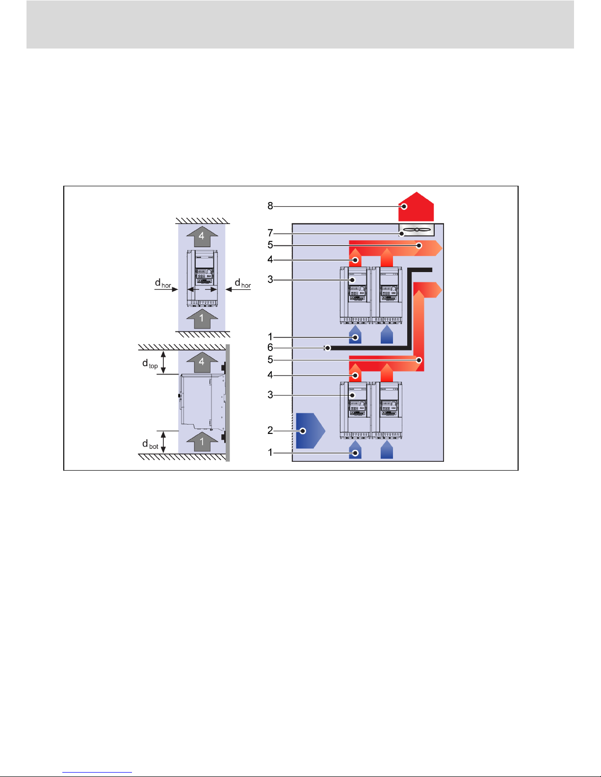
1.3 Installation Conditions........................................................................... 2
1.4 Figures and Dimensions......................................................................... 3
1.4.1 Figures................................................................................................... 3
1.4.2 Dimensions............................................................................................ 4
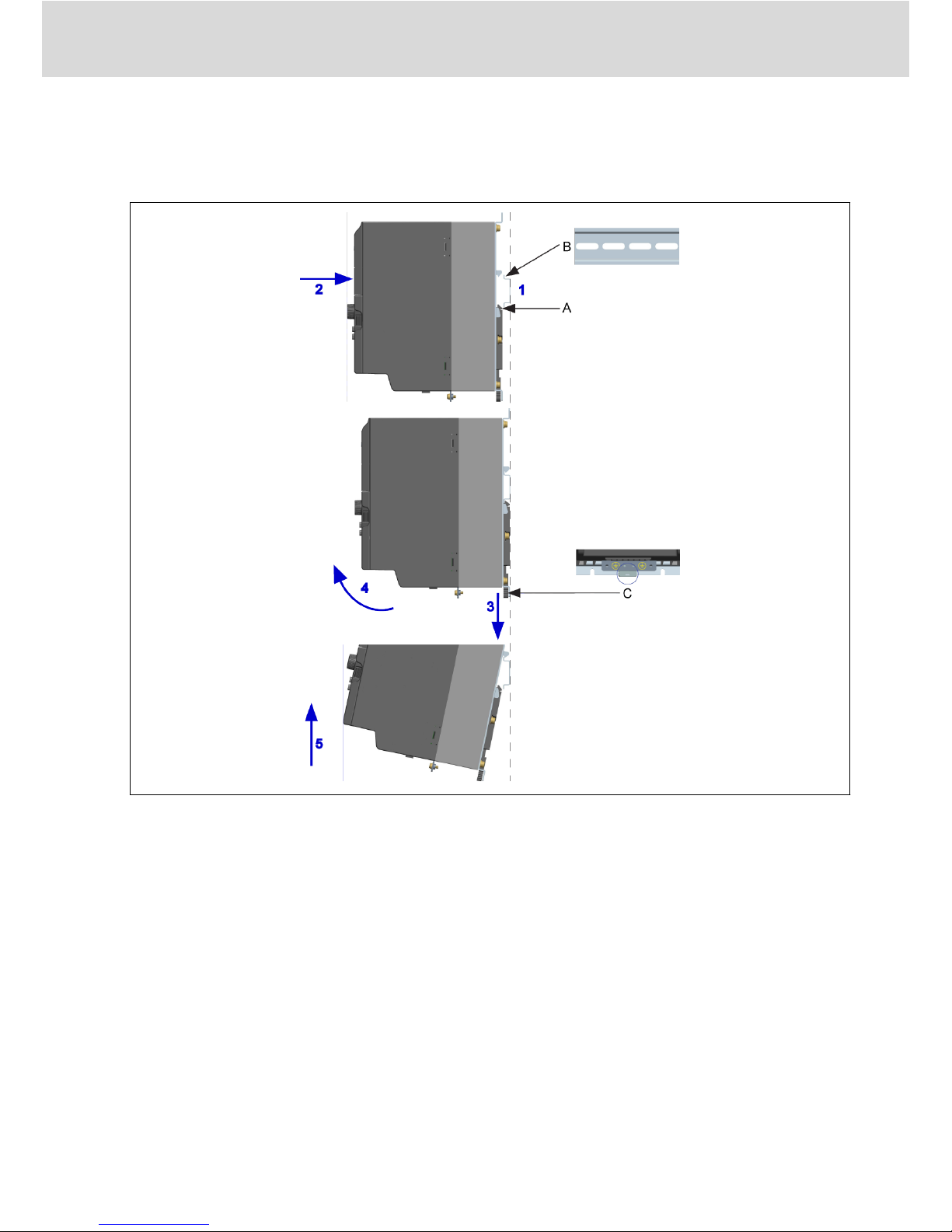
1.4.3 DIN Rail Mounting.................................................................................. 5
2 Electric Installation................................................................................ 6
2.1 Overview of Electric Connections.......................................................... 6
2.2 Cable Specifications.............................................................................. 7
2.2.1 Power Connection................................................................................. 7
Cable specification for international without USA / Canada................. 7
Cable specification for USA / Canada.................................................... 8
2.2.2 Control Signal Connection..................................................................... 9
2.3 Terminals............................................................................................. 10
2.3.1 Power Terminals.................................................................................. 10
2.3.2 Control Terminals................................................................................ 11
Control terminals figure....................................................................... 11
Control terminals description.............................................................. 12
Digital input X1...X5 NPN / PNP wiring................................................ 14
Digital output DO1a, DO1b load pull-up / pull-down wiring................ 15
Analog input terminals (AI1, AI2, +10 V, +5 V, Earth and GND)............ 15
3 Start-up................................................................................................ 16
3.1 LED Panel and Dust Cover................................................................... 16
3.1.1 LED Panel............................................................................................ 16
3.1.2 Dust Cover........................................................................................... 17
3.1.3 LED Indicator....................................................................................... 18
3.1.4 Operating Descriptions........................................................................ 19
3.2 Start-up Procedure.............................................................................. 20
3.2.1 Checking before Power-on................................................................... 20
3.2.2 Checking after Power-on...................................................................... 20
3.2.3 Checking Start-up Parameters............................................................. 20
3.2.4 Control the Motor................................................................................ 22
3.2.5 Motor Parameters Auto-Tuning............................................................. 23
VFC 3610 / VFC 5610 Bosch Rexroth AG
Table of Contents
DOK-RCON04-VFC-X610***-QU06-EN-P I