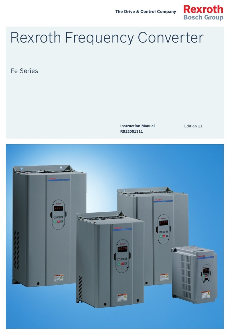
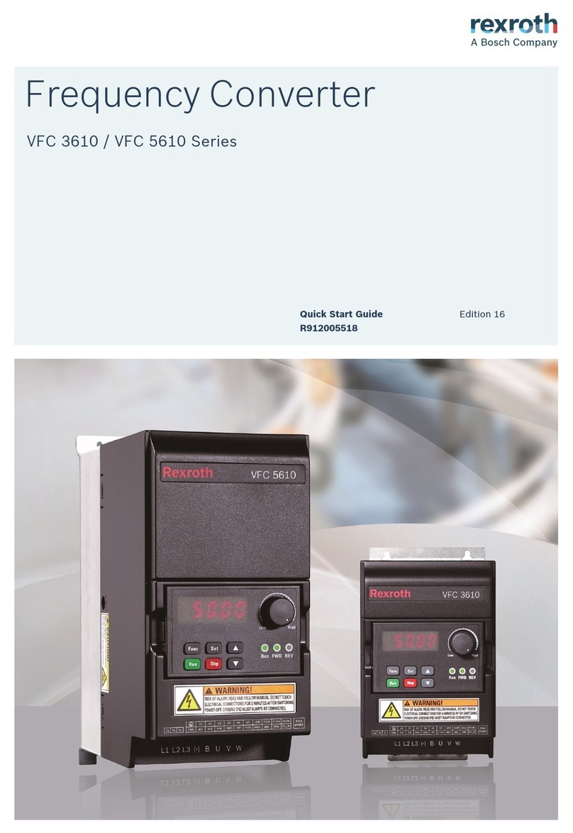
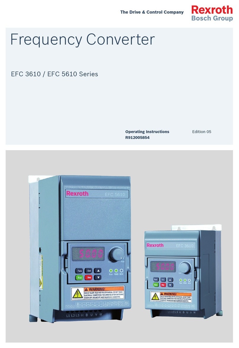
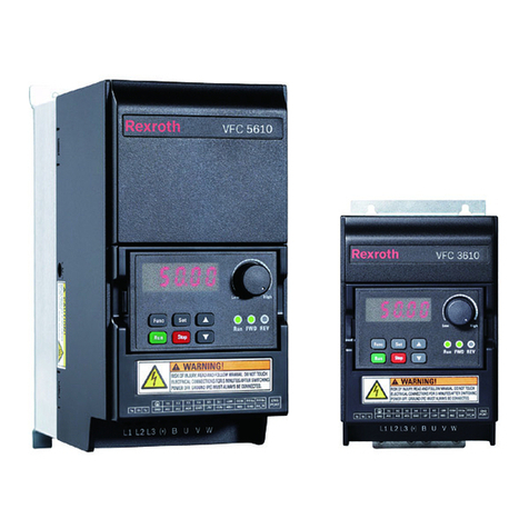
REXROTH Fv Series User manual

Rexroth Frequency Converter
The Drive & Control Company
Fv Series
Edition 05
Quick Start Guide
R912004885

Bosch Rexroth AG
Record of Revision
Edition Release Date Notes
DOK-RCON02-FV*********-IN02-EN-P 2014.02 First release
DOK-RCON02-FV*********-IN03-EN-P 2014.07
Added encoder adapt-
er information
DOK-RCON02-FV*********-IN04-EN-P 2014.11 Added new functions
DOK-RCON02-FV*********-IN05-EN-P 2015.05 Added new functions
About this Documentation
This Instruction Manual (Quick Start) is derived from the Instruction Manual
which includes the product data in details.
Never work with or control the product before reading through the Safety In-
structions in the standard delivery and the safety related chapter in the Instruc-
tion Manual.
Reference
For documentation available in other type or language, please consult your local
sales partner or check www.boschrexroth.com/fv.
Copyright
© Bosch Rexroth (Xi'an) Electric Drives and Controls Co., Ltd. 2015
This document, as well as the data, specifications and other information set
forth in it, are the exclusive property of Bosch Rexroth (Xi'an) Electric Drives
and Controls Co., Ltd. It may not be reproduced or given to third parties without
its consent.
Liability
The specified data is intended for product description purposes only and shall
not be deemed to be a guaranteed characteristic unless expressly stipulated in
the contract. All rights are reserved with respect to the content of this documen-
tation and the availability of the product.
RS-04650518eab9641b0a6846a50052ba5d-4-en-US-6

Table of Contents
Page
1 Mechanical Installation.......................................................................... 1
1.1 Visual Check.......................................................................................... 1
1.2 Ambient Conditions............................................................................... 1
1.3 Installation Conditions........................................................................... 2
1.4 Dimensions............................................................................................ 3
2 Electric Installation................................................................................ 7
2.1 Cable Specifications.............................................................................. 7
2.2 Power Terminals.................................................................................. 12
2.3 Interface Connection for Signals......................................................... 13
3 Parameter Settings.............................................................................. 23
3.1 Operating Panel................................................................................... 23
3.2 Start-up................................................................................................ 23
3.3 Operating Descriptions........................................................................ 25
3.4 Parameters........................................................................................... 26
4 Fault Indication.................................................................................... 32
Bosch Rexroth AG
Table of Contents
DOK-RCON02-FV*********-IN05-EN-P I

Bosch Rexroth AG
II DOK-RCON02-FV*********-IN05-EN-P

1 Mechanical Installation
1.1 Visual Check
After unpacking the frequency converter, perform a thorough visual check.
Check the following:
●Has the right device been supplied?
●Is the device damaged?
●Check the case for transport damage such as scratches, cracks or dents.
If you find a deviation from one of the above points, please contact your
Bosch Rexroth sales partner.
1.2 Ambient Conditions
If it is to function perfectly, the frequency converter must be installed in an envi-
ronment matching the data provided below.
Rated ambient temperature -10...40 °C (No derating)
Derating / ambient temperature Derating① (40...50 °C)
Rated altitude ≤ 1,000 m (No derating)
Derating / ambient temperature 1 % / 100 m (1,000...4,000 m)
Relative humidity ≤ 90 %
Degrees of protection IP 20 (Control cabinet mounting)
①: Refer to "9.3: Derating of Electrical Data" in the Instruction Manual.
Tab. 1-1: Ambient conditions
Bosch Rexroth AG
Mechanical Installation
DOK-RCON02-FV*********-IN05-EN-P 1/39

1.3 Installation Conditions
Depending on rating, the frequency converters are available in different sizes. In
order not to affect device cooling, the frequency converter must always be in-
stalled upright. For perfect heat dissipation, the minimum installation spacing
above and below the devices shown in the drawing must be observed.
Fig. 1-1: Installation conditions
●The frequency converter shown above is Frame 1. The minimum
installation spacing stated applies to Frame 1 to Frame 7.
●Frequency Converter Fv has no side ventilation hole, which ena-
bles parallel mounting of Fv with zero distance.
●If one frequency converter is arranged above another, make sure
the upper limit of air temperature into the inlet is not exceeded
(see chapter 1.2 "Ambient Conditions" on page 1). A baffle plate
is recommended between the frequency converters to prevent the
rising hot air being drawn into the upper converter if the upper
limit of air temperature is exceeded.
Bosch Rexroth AG
Mechanical Installation
2/39 DOK-RCON02-FV*********-IN05-EN-P

1.4 Dimensions
Frame Fv
model
Dimensions [mm] Screw
size
Net
weight
[kg]
B b T t H h h1 d D L1
1
0K40
0K75
1K50 125 75 122 1.5 275 300 315 5.5 127 5.5 M5 2.7
2K20 2.8
2
4K00
150 100 157 1.5 330 365 380 6.5 162 6.5 M6
4.8
5K50
7K50 4.9
311K0 175 100 199 2 398 432 448 6.5 204 6.5 M6 8.8
15K0 9.0
418K5
22K0 225 125 227 3.5 440 482 500 9 232 9 M8 16.5
530K0
37K0 250 150 251.5 3.5 525 567 585 9 256.5 9 M8 22.0
645K0 325 200 265 3.5 650 690 712.5 9 270 9 M8 37.0
55K0 39.0
775K0 450 300 302.5 4 700 754 779 11 307 11 M10 56.7
90K0 58.0
Tab. 1-2: Dimensions
Bosch Rexroth AG
Mechanical Installation
DOK-RCON02-FV*********-IN05-EN-P 3/39

Fig. 1-2: Frame 1, 2, 3
Bosch Rexroth AG
Mechanical Installation
4/39 DOK-RCON02-FV*********-IN05-EN-P

Fig. 1-3: Frame 4, 5
Bosch Rexroth AG
Mechanical Installation
DOK-RCON02-FV*********-IN05-EN-P 5/39

Fig. 1-4: Frame 6, 7
Bosch Rexroth AG
Mechanical Installation
6/39 DOK-RCON02-FV*********-IN05-EN-P

2 Electric Installation
2.1 Cable Specifications
2.1.1 Connecting to the Mains
Cable specification for international without USA / Canada
●ONLY USE copper wires of 90 ℃ or above with XLPE or EPR insu-
lation according to IEC 60364-5-52.
●It is recommended to use shielded cables to connect the motor.
●The specification is based on the supply voltage of 3P 380 VAC.
Fv
Model
Fuse
Power cables installation mode PE
B1 B2 E Torque / Screw Cable
size Torque / Screw
[A] [mm2] [mm2] [mm2][Nm / lb-in] (Mx) [mm2][Nm / lb-in] (Mx)
0K40 6 1.5 1.5 1.5 1.7 / 15 (M4) 10 1.7 / 15 (M4)
0K75 10 1.5 1.5 1.5 1.7 / 15 (M4) 10 1.7 / 15 (M4)
1K50 10 1.5 1.5 1.5 1.7 / 15 (M4) 10 1.7 / 15 (M4)
2K20 16 1.5 1.5 1.5 1.7 / 15 (M4) 10 1.7 / 15 (M4)
4K00 20 2.5 2.5 2.5 1.7 / 15 (M4) 10 1.7 / 15 (M4)
5K50 25 4 4 2.5 1.7 / 15 (M4) 10 1.7 / 15 (M4)
7K50 25 4 4 2.5 1.7 / 15 (M4) 10 1.7 / 15 (M4)
11K0 40 6 6 6 2.7 / 24 (M5) 10 2.0 / 18 (M5)
15K0 50 10 10 10 2.7 / 24 (M5) 10 2.0 / 18 (M5)
18K5 63 25 25 16 2.5 / 22 (M6) 16 2.5 / 22 (M6)
22K0 80 25 25 16 2.5 / 22 (M6) 16 2.5 / 22 (M6)
30K0 100 25 – 25 2.5 / 22 (M6) 16 2.5 / 22 (M6)
37K0 125 25 – 25 2.5 / 22 (M6) 16 2.5 / 22 (M6)
45K0 160 50 – 50 8 / 71 (M8) 25 8 / 71 (M8)
55K0 160 50 – 50 8 / 71 (M8) 25 8 / 71 (M8)
75K0 200 95 /
2*50 –70 /
2*35
15...20 /
133...177 (M10) 50 15...20 /
133...177 (M10)
90K0 250 95 /
2*50 –95 /
2*50
15...20 /
133...177 (M10) 50 15...20 /
133...177 (M10)
Tab. 2-1: Cable specification for international without USA / Canada
Bosch Rexroth AG
Electric Installation
DOK-RCON02-FV*********-IN05-EN-P 7/39

"–" indicates using cables of 105 ℃ or above with the same dimen-
sions as those of installation mode B1.
Bosch Rexroth AG
Electric Installation
8/39 DOK-RCON02-FV*********-IN05-EN-P

Cable specification for USA / Canada
●ONLY USE copper wires of 75 ℃ or above according to UL 508C.
●It is recommended to use shielded cables to connect the motor.
●The specification is based on the supply voltage of 3P 380 VAC.
●The cables connecting to PE terminal should assemble the UL cer-
tificated wire connector which has suitable rating for wire gauge!
Fv
Model
Fuse Power cables PE
Cable size Torque / Screw Cable size Torque / Screw
[A] [AWG] [Nm / lb-in] (Mx) [AWG] [Nm / lb-in] (Mx)
0K40 6 14 1.7 / 15 (M4) 8 1.7 / 15 (M4)
0K75 6 14 1.7 / 15 (M4) 8 1.7 / 15 (M4)
1K50 10 14 1.7 / 15 (M4) 8 1.7 / 15 (M4)
2K20 15 14 1.7 / 15 (M4) 8 1.7 / 15 (M4)
4K00 20 12 1.7 / 15 (M4) 8 1.7 / 15 (M4)
5K50 30 10 1.7 / 15 (M4) 8 1.7 / 15 (M4)
7K50 40 10 1.7 / 15 (M4) 8 1.7 / 15 (M4)
11K0 50 6 2.7 / 24 (M5) 8 2.0 / 18 (M5)
15K0 60 4 2.7 / 24 (M5) 8 2.0 / 18 (M5)
18K5 80 4 2.5 / 22 (M6) 8 2.5 / 22 (M6)
22K0 80 4 2.5 / 22 (M6) 8 2.5 / 22 (M6)
30K0 100 2 2.5 / 22 (M6) 8 2.5 / 22 (M6)
37K0 125 2 2.5 / 22 (M6) 6 2.5 / 22 (M6)
45K0 150 1/0 8 / 71 (M8) 6 8 / 71 (M8)
55K0 175 1/0 8 / 71 (M8) 6 8 / 71 (M8)
75K0 225 4/0 15...20 /
133...177 (M10) 415...20 /
133...177 (M10)
90K0 250 4/0 15...20 /
133...177 (M10) 415...20 /
133...177 (M10)
Tab. 2-2: Cable specification for USA / Canada
Bosch Rexroth AG
Electric Installation
DOK-RCON02-FV*********-IN05-EN-P 9/39

2.1.2 Signal Connection
The following requirements apply for the signal connection wiring:
●flexible cables with wire end sleeves
●cable cross-section: 0.3...0.75 mm2
●cable length: max. 20 m
●analog inputs ±10 V, VR1, VR2, VR3, +I and GND: use shielded cables
●analog inputs +I and GND: to eliminate interference from external influences,
connect +I and GND on the transducer with a 22 nF capacitor (50 V) and run
the signal cable two or three times through a ferrite ring.
Bosch Rexroth AG
Electric Installation
10/39 DOK-RCON02-FV*********-IN05-EN-P

2.1.3 Overview of Electric Connections
Fig. 2-1: Circuit diagram
Bosch Rexroth AG
Electric Installation
DOK-RCON02-FV*********-IN05-EN-P 11/39

2.2 Power Terminals
The table below describes the symbols on the frequency converter's power con-
nection terminals and their function.
Terminal Description
L1, L2, L3 Mains supply input terminals
U, V, W Frequency converter output terminals
PB External brake resistor terminal (Only applicable to 0K40...15K0 models)
P1, (+) DC choke input or DC positive bus output terminal
(-) DC negative bus output terminal
Grounding terminal
Tab. 2-3: Power terminals description
Depending on size, the position and order of the power terminals on the individ-
ual frequency converter may differ. Refer to the graphics below for the exact
connection terminal position and sequence:
0K40...15K0
Fig. 2-2: Frame 1, 2, 3
18K5...90K0
Fig. 2-3: Frame 4, 5, 6, 7
Bosch Rexroth AG
Electric Installation
12/39 DOK-RCON02-FV*********-IN05-EN-P

2.3 Interface Connection for Signals
2.3.1 Jumper Wiring
Fig. 2-4: Jumper description
Shown above are factory defaults.
2.3.2 NPN / PNP Jumper SW1
Fig. 2-5: NPN/PNP jumper SW1
The factory default for the jumper is NPN (Jumper contact at 1-3,
4-6).
The jumper SW1 determines:
1. The internal 24 V power supply or an external 24 V power supply is used
for the inputs.
2. The inputs are activated by connection of 24 V to an input (PNP / active in-
put) or connection of 0 V to an input (NPN / passive input).
Modes and signal inputs:
The jumper SW1 can switch between 0 V (NPN / passive input) and +24 V (PNP /
active input) inputs, respective external +24 V power supply is also available,
which improves the flexibility of signal input mode.
Bosch Rexroth AG
Electric Installation
DOK-RCON02-FV*********-IN05-EN-P 13/39

2.3.3 Encoder Signal Selection
Default position: 1-2
Fig. 2-6: Encoder signal selection jumper JP5
Encoder input signals are set by jumper JP5:
Position 1-2: 5 V encoder power supply is provided by PGP2.
Position 2-3: 12 V encoder power supply is provided by PGP2.
Encoder power supply
Encoder signal
Fv terminal wiring
Reference
Supply
option Voltage Encodersignal
wire Other connection
Internal
PGP1 (+24 V) A, B A-, B- Connect encoder
adapter between Fv
terminals and encod-
er signals
Wiring 1
A+, A-, B+, B- A+, A-, B+, B- Wiring 2
PGP2 (+12 V) A, B A-, B- Wiring 3
A+, A-, B+, B- A+, A-, B+, B- Wiring 4
PGP2 (+5 V) A, B A-, B- Connect A+, B+ to
PGP2 Wiring 5
A+, A-, B+, B- A+, A-, B+, B- − Wiring 6
External
+24 V A, B A-, B- Connect encoder
adapter between Fv
terminals and encod-
er signals
Wiring 7
A+, A-, B+, B- A+, A-, B+, B- Wiring 8
+12 V A, B A-, B- Wiring 9
A+, A-, B+, B- A+, A-, B+, B- Wiring 10
+5 V A, B A-, B- Connect A+, B+ to
external supply Wiring 11
A+, A-, B+, B- A+, A-, B+, B- − Wiring 12
Tab. 2-4: Encoder wiring description
Bosch Rexroth AG
Electric Installation
14/39 DOK-RCON02-FV*********-IN05-EN-P

Fig. 2-7: Encoder wiring 1...6
Bosch Rexroth AG
Electric Installation
DOK-RCON02-FV*********-IN05-EN-P 15/39

Fig. 2-8: Encoder wiring 7...12
Bosch Rexroth AG
Electric Installation
16/39 DOK-RCON02-FV*********-IN05-EN-P
Other manuals for Fv Series
2
This manual suits for next models
17
Table of contents
Other REXROTH Media Converter manuals