Reyco Granning RD950F User manual

Reyco Granning Suspensions
1205 Industrial Park Drive
Mount Vernon, MO 65712
Phone: 417-466-2178
Fax: 417-466-3964
www.reycogranning.com
Medium-Duty Truck Suspensions
Document #: D9790
Revision: G
Revision Date: 08/2023
Owner’s Manual
RD950F/RD950FP2 | Ford CW E-450

Page Left Blank Intentionally

TABLE OF CONTENTS
- 3 - D9790
REV G
08 /28 /202 3
Revision History ............................................................................................................................. 2
Introduction ................................................................................................................................... 3
Company Prole ................................................................................................................ 3
Suspension Description .................................................................................................... 3
Air Control System ............................................................................................................. 4
About This Manual ............................................................................................................. 6
General Information ...................................................................................................................... 7
Range of motion and capacity .......................................................................................... 7
Identication ...................................................................................................................... 8
Controls .......................................................................................................................................... 9
Power ON/ OFF Switch ....................................................................................................... 9
Exhaust/Inate Switch ....................................................................................................... 9
Gauges, Lights, Buzzers ................................................................................................... 10
Operation ......................................................................................................................... 10
Parts List ....................................................................................................................................... 11
Bill of Materials ................................................................................................................ 11
Main Exploded View ........................................................................................................ 12
Detailed Exploded Views ................................................................................................ . 13
Inspection & Maintenance .......................................................................................................... 15
HCV Adjustment ............................................................................................................... 16
Height Control Valve Inspection & Adju stment ............................................................. 16
Torq ue Specications ...................................................................................................... 17
Torque Table .................................................................................................................... 18
Maintenance Schedule .................................................................................................... 19
Maintenance Record ....................................................................................................... 20
Troubleshooting .......................................................................................................................... 21
Replacement Instructions and Warran ty................................................................................... 23
REV ECR # DATE CHANGE DESCRIPTION BY
E 17680 08/27/14 Updated Format, Added 1000 mile U -bolt note, Added 9860. CEW/LLG /CRG
F 18963 08/18/16 Updated Views for 9860 Change LLG
G 22823 08/28/23 UPDATED, REMOVED 7764 HCV KIT AND ADDED 6018 HCV LINKAG E
ADDE D RD950FP2 UNIT
STM

INTRODUCTION
- 4 - D9790
REV G
08 /28 /202 3
Company Profile
Reyco Granning Suspensions was formed by the merger and acquisition of two well -known
names in the heavy duty veh icle suspension industry —Reyco and Granning.
Reyco grew out of the Reynolds Mfg. Co and was rst known as a major supplier of brake
drums for heavy duty vehicles and later developed a full lin e of air and steel -spring
suspensions for trucks, buses, trail ers and motorhomes.
Granning Air Suspensions was founded in 1949 in Detroit, Michigan as a manufacturer of
auxiliary lift axle suspensions. Granning later became an innovator of independent fr ont air
suspensions for the motorhome industry.
Reyco Grannin g manufacturing facilities are certied to the ISO 9001:2015 standards, a
globally -recognized assurance that quality standards have been established and are
maintained by regular rigorous audit s.
Reyco Granning LLC was formed in early 2011 through a part nering of senior managers and
MAT Capital, a private investment group headquartered in Long Grove, Illinois.
Congratulations on your purchase of a ReycoGranning ®drive axle air suspension syste m.
Founded in 1948 by one of the pioneers of air suspensions, ReycoGranning ®Air Suspensions
supplies drive and tag axle air suspension systems to a variety of original equipment
manufacturers as well as to the aftermarket industry. The R -Series are utili zed by OEM
customers in applications such as recreational vehi cles, shuttle bus, trailer, chassis builders,
Type I and III ambulances and class 3 through 8 truck applications. This product line now
exceeds 25 models that cover all major chassis utilized i n the above applications.
Suspension Description
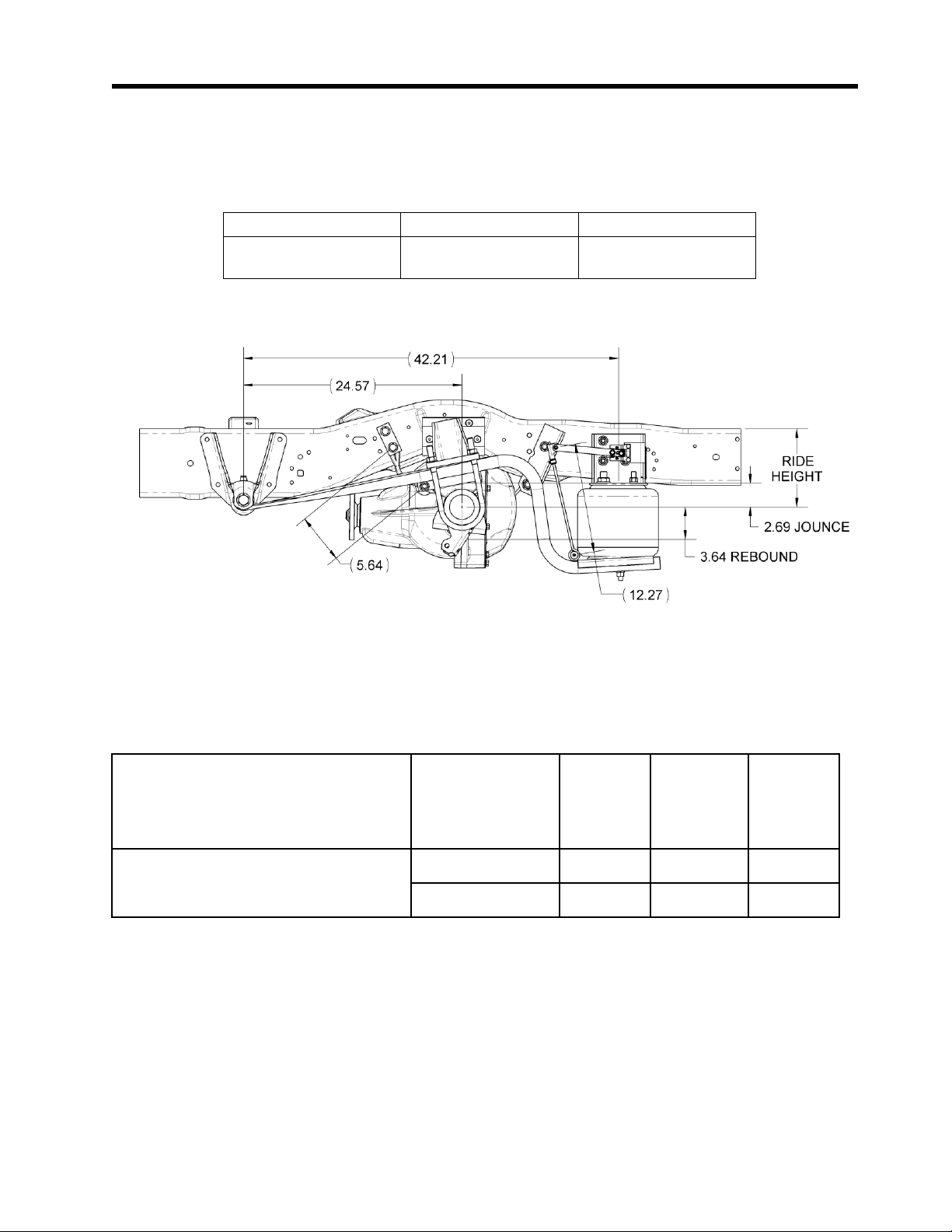
A ReycoGrann ing®drive axle air suspension system is a replacement rear suspensions system
that consists of an air control system, air springs, trailing arm beams, brackets, and mounting
hardware. In gener al, the air suspension works by maintaining a constant ride he ight by
adjusting the amount air pressure in the air springs. This allows the vehicle to remain level,
regardless of loading. By varying the amount of air pressure in the springs, a comfortabl e ride
is maintained whether lightly or heavily loaded. This is the major dierence between an air
suspension and a conventional steel spring suspension. The steel spring suspension is usually
designed for heavily loaded condition and thus yields a hars h ride in lightly loaded conditions.
In addition, the steel s pring suspension does not maintain a constant ride height under varying
load conditions.
By maintaining a constant ride height, the horizontal center of gravity, steering geometry, and
even the headlights remain level. The benets of an air ride are:

INTRODUCTION
- 5 - D9790
REV G
08 /28 /202 3
1. Dr iver/passenger comfort,
2. Protection of cargo, chassis and body components,
3. Reduced stress fatigue to chassis frame rails.
4. Greater stability and control.
A unique feature to the ReycoGrannin g® drive axle air suspension system is the wear towers
and wea r blocks. These time proven components prevent unwanted side to side lateral
motion without the use of costly and complex track rods.
Air Control System
A primary subsystem of a ReycoGranning ®drive axle air suspension system is the Air Control
System. F or information on how the Air Control System works, and service information for
the Air Control System, refer to the manual for your specic Air Control System.

INTRODUCTION
- 6 - D9790
REV G
08 /28 /202 3
About This Manual
This publicati on is intended to acquaint and assist maintenance personnel in the maintenance,
service, repair and rebuild of the Reyco Granning®RD 950 F Rear Suspension. It is important to
read and understand the entire Technical Procedure publication prior to performing any
maintenance, service, repair, or rebuild of this product
Reyco Granning ® Air Suspensions reserves the right to modify the suspension and/or
procedures and to change specications at any time without notice and without incurring
obligation. Contact customer service at 800-753-0050 for information on the latest version of
this manual.
You must follow your company safety procedures when you service or repair the suspension.
Be sure you read and understand all the procedures and instructions before you begin work
on the suspension.
Reyco Granning ® uses the foll owing types of notes to give warning of possible safety
problems and to give information that will prevent damage to equipment.
WARNING
A warning indicates procedures that must be followed exactly. Serious personal injury
can occur if the procedure is not followed.
CAUTION
A caution indicates procedures that must be followed exactly. Damage to equipment or
suspension components and personal injury can occur if the procedure is not followed.
NOTE
A note indicates an operation, procedure or instruction that is important for correct
service.
Some procedures require the use of special tools for safe and correct service. Failure to use
these special tools when required can cause personal inju ry or damage to suspension
components.
The latest revision o f this publication is available online at http://www.Reyco Granning.com/
Reyco Granning ® Air Suspensions has developed this owner’s manual to aid in the
maintenance of Reyco Granning ® ’s rear suspensions.

GENERAL INFORMATION
- 7 - D9790
REV G
08 /28 /202 3
Range of Motion and Capacity
The following table lists the various models and their respective capacities.
Model
Capacity
Axle Capacity
RD 950F /RD 950 FP2 9,600 lbs 9,600 lbs
Overloading the sus pension may result in adverse ride and handling characteristics.
Figure 1: Suspension range of motion
Note: The ride height is for the completed vehicle with body and components. See table below
for correc t vehicle dimensions.
Chassis
Reyco
Granning®
Suspension
Model
Ride
Height *
Jounce
Travel
Rebound
Travel
E450 Cutawa y
RD950F 8.80” 2.69” 3.64 ”
RD950FP2 10.80” 2.69” 3.64 ”
*Ride height is measured from the axle center (flat and level) to the top of the original
vehicle frame behind the axle where the frame flattens (just behind the air spring) as
shown.

GENERAL INFORMATION
- 8 - D9790
REV G
08 /28 /202 3
Identification
The suspension model and se rial number are stamped on an aluminum tag tha t is riveted to
the driver side U pper Air Spring Pad Assembly (See View “E ”). The serial number is used by
Reyco Granning ®for control purposes and should be referred to when servic ing the
suspension (See Figu re 2 ).
Figure 2: Suspension Identification

PARTS LIST
- 9 - D9790
REV G
08 /28 /202 3
RD950F
ITEM# QTY. PART# DESCRIPTION
1 2 5764
B
ACKING PLATE (SHIM) 16 2 7750
W
EAR TOWER ASSEMBLY
2 1 4638
W
EAR PAD, LH 17 4 7762
U
-BOLT Ø 5/8 -18 x9.5 (RD950 F)
3 1 4639
W
EAR PAD, RH 7805
U
-BOL T Ø 5/8 -18 x11 .4 (RD950 FP2 )
4 8 4356
SF
HCS 3/8 -24 X 1 1/2 8 PH 18 8 4599
L
FN 5/8 -18 G PH
5 8 109
F
W 3/8 .406X.812X.065 ZP 19 2 6018
H
C V LINKAGE (12.25)
6 8 89422298
L
N 3/8 -24 GR. 8 ZN 20 2 5367
M
OUNT, AIR SPRING, LOWER
7 1 7759
U
PPER AIR SPR PAD ASY. L.H. 21 2 7765
A
IR SPRING
8 1 7760
U
PPER AIR SPR PAD ASY. R.H. 22 4 8103323
SL
W 1/2 .523X.873X.135 PL
9 8 309
F
HB 1/2 -13 X 1 1/4 GR 8 ZN 23 4 8120378
N
1/2 -13 5 ZN
10 14 308
L
FN 1/2 -13, GR. G ZN 24 2 8131017
F
W 3/4 .812X1.469X.134 ZP
* 11 1 986 0
KI
T, CROSSMEMBER 25 2 8219758
J
N 3/4 - 16 5 ZN
11.1 1 701727 -01
RO
D, 5/8 -18 X 44", TRI -8 26 2 7753
R
EB. STRAP BRKT. ASY.
11.2 1 822 7
B
RACKET, XMEMBER M TG, LH 27 4 702638 -01
F
HB 1/2 -13 X 3 1/2 GR.8 PH
11.3 1 8228
B
RACKET, XMEMBER MTG, RH 28 2 5763
SLE
EVE - REBOUND STRAP
11.4 1 K711154
KI
T, H DWARE - 9860 XMEMBER 29 2 4368
SLE
EVE, REBOUND STRAP
11.4.1 2 288
F
N 5/8 -18 GR.5, SERRATE D, ZN 30 2 7755
R
EBOUND STRAP
11.4.2 2 308
L
FN 1/2 -13, GR. G ZN 31 2 225
H
FW 1/2 .531X2.00X.125 ZP
11.4.3 2 309
F
HB 1/2 -13 X 1 1/4 GR 8 ZN 32 2 219
F
HB 1/ 2-13 X 5 GR.8 PH
11.4.4 2 4599
L
FN 5/8 -18 G PH * 33 1 708580 -01
H
EAT SHIELD, FLEXIBLE
11.4.5 2 89429288
HH
N 5/8 -18 GR ASTM A194 -2H * 34 1 711358 -01
I
NSTALLATION, SERIAL TAG
*11.5 1 D9860
D
RAWING, XMEMBER KIT 9860 34.1 1 2617
PL
ATE -SERIAL NO
* 12 2 7747
S
PRING BEAM ASY. (RD950F) 34.2 2 188
P
OP RIVET
12.1 1 6274
B
USHING * 35 1 D9793
KI
T, DR W/DOCU MENT RD950F
12.2 1 708706 -01
S
PRING BEAM * 35.1 1 D5602
S
H T, CAUTION, COMP FITTINGS
13 2 700690 -02
F
HB M18 -2.5X140 10.9 PH * 35.2 1 D9789
D
WG, INS TALLATION RD950F
14 2 700725 -01
N
UT & RETAINER M18X2.5 * 35.3 1 D9792
D
OC, INSTALL INSTR RD950F
15 2 7761
A
XLE WEDGE SP CR 1.0” (RD950F ) *35.4 1 D9791
D
OC, INSTALL. CHECKLIST
2 7806
A
XLE WEDGE SP CR 3. 0” (RD950FP2 ) *35.5 1 D9790
D
OC, OWNERS MANU AL
*Not Shown/Called Out

PARTS LIST
- 10 - D9790
REV G
08 /28 /202 3
Main Exploded View
Figure 6: Main exploded view

PARTS LIST
- 11 - D9790
REV G
08 /28 /202 3
Detailed Exploded Views
Figure 7: Detailed exploded views “A”, “B”, & “C”

PARTS LIST
- 12 - D9790
REV G
08 /28 /202 3
Detailed Exploded Views
Figure 8: Detailed exploded views “D”, “E”, & “F”

INSPECTION & MAINTENANCE
- 13 - D9790
REV G
08 /28 /202 3
Perform a thorough visual inspection of the suspension to ensure proper assembly
and to identify broken parts and loose fasteners each time the vehicle suspension is
serviced. Do the following during an inspection.
Fasteners - Using a ca librated torque wrench check that all the fasteners are tightened
to the proper torque.
Wear and Damage - Inspect components of the suspension for wear and damage.
Look for bent or broken components. Replace all worn or damaged components.
Operation - Check that all components move freely through the complete turning arc.
CAUTION: Reyco Granning ® recommends replacing any damaged or out-of-
specification components. Reconditioning or field repairs of major rear
suspension components is not allowed.
No te: Refer to Section 1 for identication of components.
NOTE: Reyco Granning ® recommends the use of a maintenance pit or full
vehicle lift during the inspection of components.
WARNING: Never work under a vehicle supported by only a jack. Jacks can
slip or fall over and cause serious personal injury. Always use safety stands.

INSPECTION & MAINTENANCE
- 14 - D9790
REV G
08 /28 /202 3
Torque Specifications
Most threaded fasteners are covered by specications that dene required mechani cal
properties, such as tensile strength, yield strength, proof load, and hardness. These
specications are carefully considered in initial selection of fasteners for a given
application. To assure continued satisfactory vehicle performance, replacement
fasteners used should be of the correct strength, as well as the correct nominal
diameter, thread pitch, length, and nish.
Figure 10: Grade Markings on Bolts
Grade
Lock Nut
Grade B, F
Lock Nut:
Grade C, G
Identification
3 Dots
6 Dots
Figure 11: Grade Markings on Lock
Nuts

INSPECTION & MAINTENANCE
- 15 - D9790
REV G
08 /28 /202 3
Reyco Granning Recommended Torque Specifications
Item
Assembly
Fastener
Torque
1
Spring Beam Pivot Connection
FHB M18 x 2.5 x 140, Gr. 10.9
240-290 ft-lbs
2
Upper Air Spring Pad Mount (to Frame)
FHB 1/2 -13 x 1.25, Gr. 8 ZN (LFN 1/2 -13, Gr. G ZN)
80 ft-lbs
3
Air Sprin g (to Spring Beam )
(N 1/2 -13, Gr. B ZN)
35 ft-lbs
4
Air Spring Stud Nut ( to Pad Asy ) (N 1/2 -13 , Gr. 5 ZP )
35 ft-lbs
5
Air Spring Air Port Nut (to Pad Asy )
(JN 3/4 -16, Gr. 5 ZP )
35 ft-lbs
6
Wear Pad (to Chassis )
CSB 3/8 -24 x 1.5, Gr. 8 ZN (LN 3/8 -24, Gr. C ZN)
10-15 ft-lbs.
7
Rebound Strap Upper & Lower Mount
FHB 1/2 -13 x 3.5 & 5, Gr.8 (LFN 1/2 -13 , Gr. G ZN)
80 ft-lbs
8
HC V Linkage (to HCV & Lower Brkt) (N 1/4 -20, Gr . 5)
10 ft-lbs
9
U-Bolt Nuts (See Figure A)
U-BOLT, AXLE SEAT ( LFN 5/8 -18, Gr. G )
190 ft-lbs
10
Crossmember Plate Mount (to Frame)
FHB 1/2 -13 x 1.25, Gr. 8 ZN, (LFN 1/2 -13 , Gr. G ZN )
90 ft-lbs
11
Cross member Rod N ut (LFN 5/8 -18, Gr. G PH )
127 ft-lbs
*12
*Wheels (See Vehicle Owners) *See Vehicle Owners Manual
**
* Not Shown
*
*Follow procedures and torques listed in Vehicle Maintenance/Owner’s Manual
N
ote: Torque values listed above apply only if Reyco Granning supplied fasteners are used. For
information regarding component replacement or technical service call 1-800-753-1060
See Figure 12 for Illustrated Torque Callouts

INSPECTION & MAINTENANCE
- 16 - D9790
REV G
08 /28 /202 3
Figure 12: Illustrated torque callouts

INSPECTION & MAINTENANCE
- 17 - D9790
REV G
08 /28 /202 3
Maintenance Schedule
GENERAL
MAINTENANCE
SERVICE TO BE PERFORMED
MILEAGE IN THOUSANDS
12
24
36
48
60
72
84
96
Spring Beam Pivot
Connection
Check bolt torque. X X X1
Inspect for contact between Spring Beam
and Hanger. X X X X X X X X1
Inspect for bushing wear.
X
X
X
X
X
X
X
X
1
Air Springs Inspect for proper clearance (1”
minimum all around). X
Check upper mount nut and lower
mount bolt torque.
X
Inspect for signs of chang or wear.
X
X
X
X
X
X
X
X
1
Check for air line tting torque. X
Inspect for air leaks using soapy water
solution. X
Height Control Valve
Linkage
Inspect for signs of bending, binding, or
slippage. X X X X X X X X1
Air Fittings and Air
Lines
Inspect for air leaks using soapy water
solution X
Inspect for signs of chang, cracking, or
wear X X X X X X X X
Shock Absorbers
Check stud mount and lock nut torque.
X
Inspect shocks for signs of uid leak,
broken eye ends, loose fasteners, or
worn bushings.
X X X X X X X X1
Axle Connection / U -
Bolts 4
Check “U” -bolt nut torque 4and gap
between wear pad and wear tower. X X X X X X X X
Wheels
2
Check lug nut torque
3
X
X
X
X
X
X
X
X
Air Compressor Check a ir compressor compartment or
enclosure for proper airow and venting.
X X X X X X X X
Rear Alignment
Inspect (after rst 1000 -3000 miles)
X
X
X
X
1
Air Fittings and Air
Lines
Inspect for air leaks using soapy water
solution.
X
Inspect for s igns of chang, cracking, or
wear.
X X X X X X X X1
1Continue to perform specied maintenance every 12,000 miles.
2See your vehicle’s owner’s manual for instructions regarding t he maintenance of wheels and tires.
3 Wheel lug nuts must be retightened to proper torque specications as per the vehicle or chassis
manufacturer’s Owner Guide.
4U-bolts require an initial re-torque at 1000 miles, then follow regular mainte nance schedule in the
chart above.

INSPECTION & MAINTENANCE
- 18 - D9790
REV G
08 /28 /202 3
Maintenance Record*
N
ame of Owner
A
ddress of Owner
D
ate of Purchase
N
ame and Address of Dealer
M
odel of Vehicle
V
ehicle Identication Number
S
uspension Model Number:
RD950F/RD950FP2
S
uspension Serial Number:
Inspection and Maintenance Item
Date Mileage Service Performed
*In order to take advantage of warranty, Mainte nance Record should be lled out
and attached to warranty claims when submitted.

TROUBLE SHOOTING
- 19 - D9790
REV G
08 /28 /202 3
SYMPTOMS
POSSIBLE CAUSES
REMEDIES
Tires wear out quickly or have
uneven tire tread wear.
Note: Wear pattern will indicate
possible cause(s). Consult tire
manufacturer for guidance.
1
) Tires have incorrect pressure.
2
) Tires out of balance.
3
) Incorrect ride height.
4
) Incorrect rear axle alignment.
5
) Improper (mismatched) tires
and
wheels.
1
) Put specied air pressure in
t
ires.
2
) Balance or replace tires.
3
) Adjust ride height to specied
se
tting.
4
) Align rear axle to specied thrust
an
gle.
5
) Ins tall correct tire and wheel
c
ombination.
V
ehicle rolls side to side
e
xcessively.
1
) Shock absorbers worn.
2
) Shock eye bushings worn.
3
) Axle U -bolts are loose
4
) Loose or w orn Spring Beam
Pi
vot connection(s).
5
) Loose or worn Spring Beam
Pi
vot bushing(s) .
6
) Check for air leak including the
h
eight control valve.
1
) Replace shock absorbers as
n
eeded.
2
) Check and replace as needed..
3
) Tighten (see previous torque
c
hart) or r eplace as required
4
) Tighten (see previous torque
c
hart) or replace as required
5
) Replace as required
6
) Check height control valve and
r
eplace as required.
Vehicle ride is too harsh and/or
suspension contacts stops
excessively.
1
) Shock absorbers worn.
2
) Incorrect ride height.
3
) Vehicle overloaded.
4
) Air spring supply lines leaki ng
or
obstructed.
5
) Vehicle system air pressure
b
elow specication.
6
) Jounce bumper in air spring
w
orn or broken.
7
) Air Suspension not turned on.
8
) Defective Height Cont rol
V
alve(s)
9
) Height Control Linkage
di
sconnected or damaged
1
) Replace shock ab sorbers as
n
eeded.
2
) Adjust ride height to specied
se
tting.
3
) Check wheel loads and correct
a
s needed.
4
) Check air line connections and
r
emove obstructions.
5
) Check air pressure and correct
a
s needed.
6
) Check and replace air spring as
r
equired.
7
) T urn on air suspension.
8
) Replace height control valve as
r
equired.
9
) Reattach or replace as required.
V
ehicle ride is too soft.
1
) Shock absorbers worn.
2
) Incorrect ride height.
1
) Replace shock absorbers as
n
eeded.
2
) Adjust ride height to specied
setting.

TROUBLE SHOOTING
- 20 - D9790
REV G
08 /28 /202 3
SYMPTOMS
POSSIBLE CAUSES
REMEDIES
S
uspension does not maintain
ri
de height.
1
) Air leak.
2
) Internal leak in height control
v
alve.
3
) Height control valve linkag e
lo
ose.
4
) Air spring chafed or worn.
1
) Check connections with soapy
w
ater solut ion and repair or
r
eplace as needed.
2
) Check height control valve and
r
eplace as required.
3
) Check and tighten linkage as
n
eeded.
4
) Check air spring and replace as
needed.
A
ir compressor runs excessively
1
) Air leak.
2
) Internal air leak in height
c
ont rol valve.
3
) Moisture ejector valve stuck
op
en.
4
) Check valve installed
in
correctly.
5
) Dump valve(s), or “kneeler(s)”,
l
eaking.
6
) Height Control Valve stuck in
t
he exhaus t position.
1
) Inspect all air lines, ttings, and
air
springs with a soapy water
s
olution. Repair, retighten, or
r
eplace as required. Note: Plastic
air
lines must be cut square. See
A
ir Control System Parts List
(
General Notes) for additional
no
tes.
2
) Insert exhaust tube into a cup of
w
ater and examine for bubbles.
Thi
swill show e vidence of both
inl
et and exhaust valve leaks.
3
) Replace components.
4
) Check and replace if necessary.
A
rrow should point away from the
air
compressor head. Correct if
ne
cessary.
5
) Check and replace if necessary.
6
) Locate obstruction and remove
or re locate interference.
A
ir compressor will not start
1
) Inline fuse burnt or circuit
b
reaker tripped.
2
) Air compressor motor burnt
ou
t.
3
) Disconnected or broken wire.
4
) Ignition switch and/or
suspension power switch not on.
1
) Replace or reset.
2
) Inspec t and replace as required.
3
) Inspect and correct or replace if
n
ecessary.
4
) Turn on ignition switch and/or
s
uspension switch.
This manual suits for next models
1
Table of contents
Other Reyco Granning Automobile Accessories manuals