Reznor EURO-X 1000 D User manual

Reznor® 0108X1DHGBEN
GAS FIRED AIR HEATERS TYPE EURO-X 1000 D
Centrifugal Fanned Forced Convection Appliances with
Thermal Electric Burner Control for use as:
Type B11 Open flued Appliances
May be used with Reznor "Euroventer" Flue Gas Fan as:
Type B14 Appliances
This document applies to EURO-X 1000 D appliances with:
Thermoelectric or Hot Surface Ignition burner controls
These appliances meet the following EC Directives:
Dir. CE 90/396/EEC GAD
Dir. CE 89/336/EEC EMC
Dir. CE 73/ 23/EEC LVD
Please read this document carefully before commencing the installation and leave it with the
user or attached to the appliance or gas service meter after installation.

0108X1DHGBEN 2
INDEX Page
1. General..................................................................................................................................................2
2. Technical data........................................................................................................................................3
3. Dimensions............................................................................................................................................5
4. Installing................................................................................................................................................6
5. Air supply requirements...........................................................................................................................9
6. Flue system .........................................................................................................................................11
7. Gas connection ....................................................................................................................................13
8. Electrical connection .............................................................................................................................13
9. Commissioning.....................................................................................................................................14
10 Servicing .............................................................................................................................................17
11 Short parts listing .................................................................................................................................22
12. Gas conversion ..................................................................................................................................23
13. Fault finding ......................................................................................................................................24
14. Health and Safety information..............................................................................................................25
15. User instructions................................................................................................................................26
N.B. If optional equipment is supplied with this appliance please refer to the additional instructions supplied with the
option.
SECTION 1 GENERAL
1.1 Before installation, check that the appliance as
described on the packaging label is in accordance
with the correct type and model as specified on the
data plate and complies with your customer order.
1.2 After unpacking the appliance, leave it fastened to the
wooden pallet until it has been suspended or until just
before base mounting.
This affords protection to the painted underside which
is normally exposed to view after installation.
1.3 Please read this document before commencing
installation.
1.3 These instructions are only valid for the country of
use indicated on the appliance i.e.: GB - IE.
If these symbols are not shown, it is necessary to
obtain appropriate technical instructions which will
provide information concerning the necessary
modification of the appliance for the conditions of use
in the country concerned.
Such instructions may be obtained upon request from
your supplier.
1.5 Check that the local distribution conditions of
electricity supply, type of gas and pressure, and
adjustment of the appliance are compatible.
1.6 When installed in Great Britain the total installation
must comply with the requirements and
recommendations of British standard BS 6230 1991.
"Installation of Gas Fired Forced Convection Air
Heaters for Commercial and Industrial Space
Heating".
The Installation must also be in accordance with the
relevant requirements of "The Gas Safety (Installation
and Use regulations) and (Amendment Regulations
1990)" and The "Building" and "Electrical
Regulations" (in GB the IEE Regulations). The
requirements of the "Local Building Standards Office",
the premises "Insurance" undertaking and the"Fire
Office" must also be observed.
1.7 Unauthorized modification of this appliance or
departure from use in the manner for which it was
intended by the manufacturer or installation in a
manner contrary to these instructions, may constitute
a hazard and jeopardize all warranties. Deviations
should only be carried out after formal consent has
been obtained from the manufacturer.
1.8 Ensure the environment in which the air heater will be
installed will not create a hazard i.e. where excessive
(volatile) dust, flammable or corrosive substances
and/or vapours and combustible materials may be
present.
1.9 This appliance has been tested, and set according to
the data plate before leaving the factory.

0108X1DHGBEN3
SECTION 2. TECHNICAL DATA
Table 1. APPLIANCE DATA
Type EURO-X ... 1025D 1030D 1035D 1045D 1055D 1075D 1095D
Gas category 'Cat.' II2H3+
Air supply and flue type B11 or B14 1
Heat input (Hs) 'Qn' kW 30,28 34.94 43,26 52,00 64,67 88,96 118,7
Heat input (Hi) 'Qn' kW 27,30 31,50 39,00 46,90 58,30 80,20 107,0
High heat output kW 23,8 27,5 34,2 40,8 50,8 69,9 93,2
Number of jets 4 5 7 9 12 16
natural gas ∅mm 2,4 2,2 2,4 2,6
Jet size propane/butane ∅mm 1,35 1,30 1,25 1,35 1,40
natural gas mbar (GB) =17,5 (IE) = 20,0
propane mbar 37,0
Gas supply
pressure 'P' 2
butane mbar 28,0
Burner pressure natural gas mbar 8,4 6,0
natural gas 3m3/h 2,89 3,33 4,13 4,96 6,17 8,49 11,33
butane G30 kg/h 2,21 2,55 3,15 3,80 4,72 6,49 8,66
Gas consumption propane G31 kg/h 2,16 2,49 3,09 3,71 4,62 6,35 8.48
Gas service connection (not supply line size) Rc ¾
Electrical service (protection class IP 20) 230/240V 1 N ~ 50 Hz
Total electrical rating 4kW
Weight net kg
Weight shipping ± kg
1 Category B14 only applies when used with a Reznor "EUROVENTER" flue gas fan
2 Maximum gas pressure at inlet to appliance = 50,0 mbar
3 Natural gas G 20, calorific heating value 10,48 kWh/m3on Hs @ 15 °C & 1013 mbar
Propane G 31, calorific heating value 14,0 kWh/kg. Butane G 30, calorific heating value 13,7 kWh/kg
4 Total electrical rating for appliances with hot surface ignition is exceeded by 130 W for ± 30s at start up
Table 2 Minimum air volumes for maximum temperature rise.
Standard model Euro-X... 1025D 1030D 1035D 1045D 1055D 1075D 1095D
Minimum air volume m3/h 1800 2200 2660 3110 3940 5400 7190
Maximum temperature rise ∆T K 39 37 39 39 38 38 38
NOTE: The maximum static pressure that may be applied to the EURO-X...D series is 800 Pa

0108X1DHGBEN 4
Figure 1. PRESSURE LOSS FOR AIR FLOWS THROUGH EURO-X 1000 D HEAT EXCHANGER
Figure 2. COMBUSTION CIRCUIT DEW-POINT OCCURRENCE CHART
Note:
If operation within the condensation zone is unavoidable due to by-pass restrictions, optional AISI 316 stainless steel
combustion circuit components should be ordered to reduce the risk premature corrosion within the combustion/flue circuit

0108X1DHGBEN5
Figure 3. DIMENSIONS
Left hand side (controls side) Front view
Top plan Rear view
Legend figure 1
1. Flue socket
2. Gas connection Thermoelectric
3. Gas connection Hot Surface Ignition
4. Electrical and Controls connections
5. Service and User access panels
6. Optional suspension point brackets
Table 3. DIMENSIONS REFERENCE FIGURE 3
MODEL EURO-X ... 1025D 1030D 1035D 1045D 1055D 1075D 1095D
A1 Width overall 520 590 730 870 1080 1360
E Flue centres 290 325 395 465 570 710
Flue internal dia mm 130 153 181 202 202 252
G1 Optional suspension points centres 359 429 569 709 919 1199
K1 Width of duct spigot OA 360 430 570 710 920 1200
L1 Opposite controls side clearance 150 300
L min Essential service access clearance 550 620 750 900 1100 1400
W Centre of flue to back panel 127 137 151 162 162 169

0108X1DHGBEN 6
SECTION 3 INSTALLING
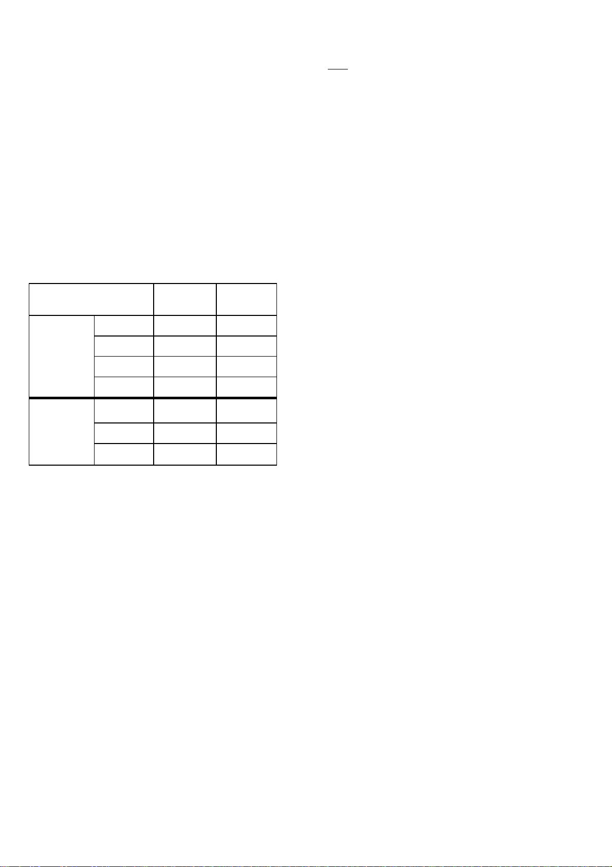
3.1 When installed as an in-line duct heater i.e. not fitted
within an air handling appliance cabinet it is necessary
to ensure that clearance is maintained around the
appliance from combustible materials and for service
access. The clearances necessary to ensure safety for
combustibles is 150 mm on all sides. Service access
should be allowed on the controls side of the
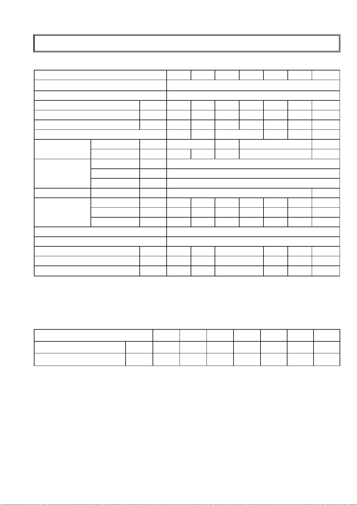
appliance equal to the dimensions given in table 3 this
distance allows for the removal of the burner tray
assembly, necessary when servicing the appliance.
3.2 Ensure that the structural elements which will be used
to suspend or support the appliance, are adequate to
carry the weight of the appliance and its ancillary
components i.e. flue system and any dependant duct-
work.
3.3 Ensure that the air heater is installed in a level plain
both laterally and horizontally.
3.4 If the air heater is to be base mounted in an open
position then it must be secured to the floor or other
supporting device/s.
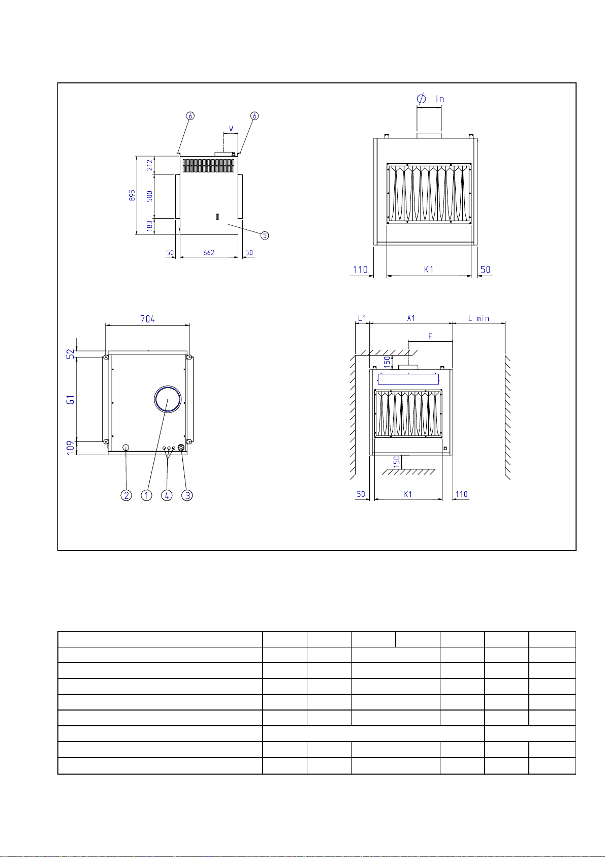
3.5 4 suspension brackets with holes φ10.5 mm are
available as optional accessories.
Use 10 mm φrods for suspending the heater when
using these Reznor options.
3.6 If the appliance is to be suspended or base mounted
from cantilever brackets, specially designed wall
brackets should be manufactured to suit the
application respecting the clearances indicated in 3.1
above and the live load factors the appliance and it's
air handler will impose.
3.7 After suspension, the air heater should be rigid so as
to avoid placing a strain on the flue system, gas
services, electrical wiring and duct system.
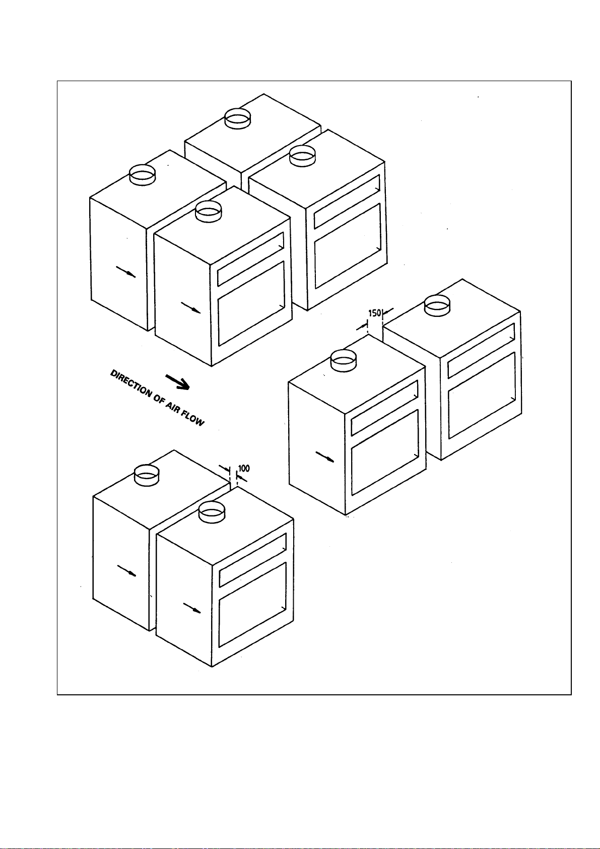
3.8 Euro-X 1000 D series air heaters, wether or not they
are installed within an air handling appliance may be
installed in multiple form as illustrated in figure 4. In
all instances the air flow passed through the
appliance/s should not exceed the volumes required to
ensure that dew point conditions within the
combustion circuits/s as indicated in figure 3 do not
occur.
By-passes should be constructed as necessary to
ensure that the optimum temperature rises are met
taking into account the pressure resistance of the air
heater as indicated in figure 2.
When designing by-pass ducts ensure that the
requirements for service access, flue and
controls connections are maintained. An adjustable
damper should be included within by-pass ducts to
enable air flow pressure and volume to be adjusted
after installation.
When fitting Euro-X 1000 D air heaters in a side by
side configuration it is necessary to specify this
requirement when ordering type D models. Opposite
handing of the appliances may be required. Whilst the
air may be passed through the appliance from either
end, provision for locating the thermal over-heat
(limit) control device has to be made so that the air
off side (the hottest side) is monitored for this
purpose. Further to this the flue down draught spillage
slot (normally at the front air discharge side of the
appliance) must not become obstructed with another
air heater or air ducting. A distance of 200 mm must
be maintained for flue products to freely spill.
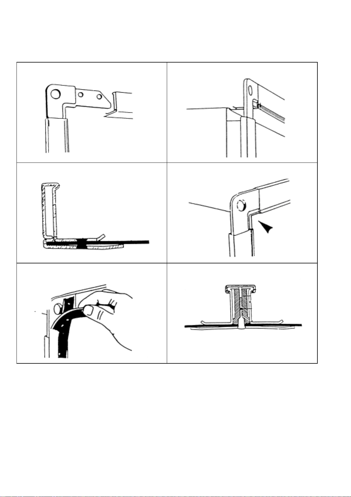
3.9 Figure 5. illustrates the recommended principle that
should be used for the connection of ducting or air
handling appliance element transitions.
A positive seal must be maintained between the air
circuit and the air heater, this is particularly important
when the air heater is installed within an air handling
cabinet. A neutral pressure zone around the appliance
must be maintained to ensure that the atmospheric
burner operates at all times at normal ambient
pressure.
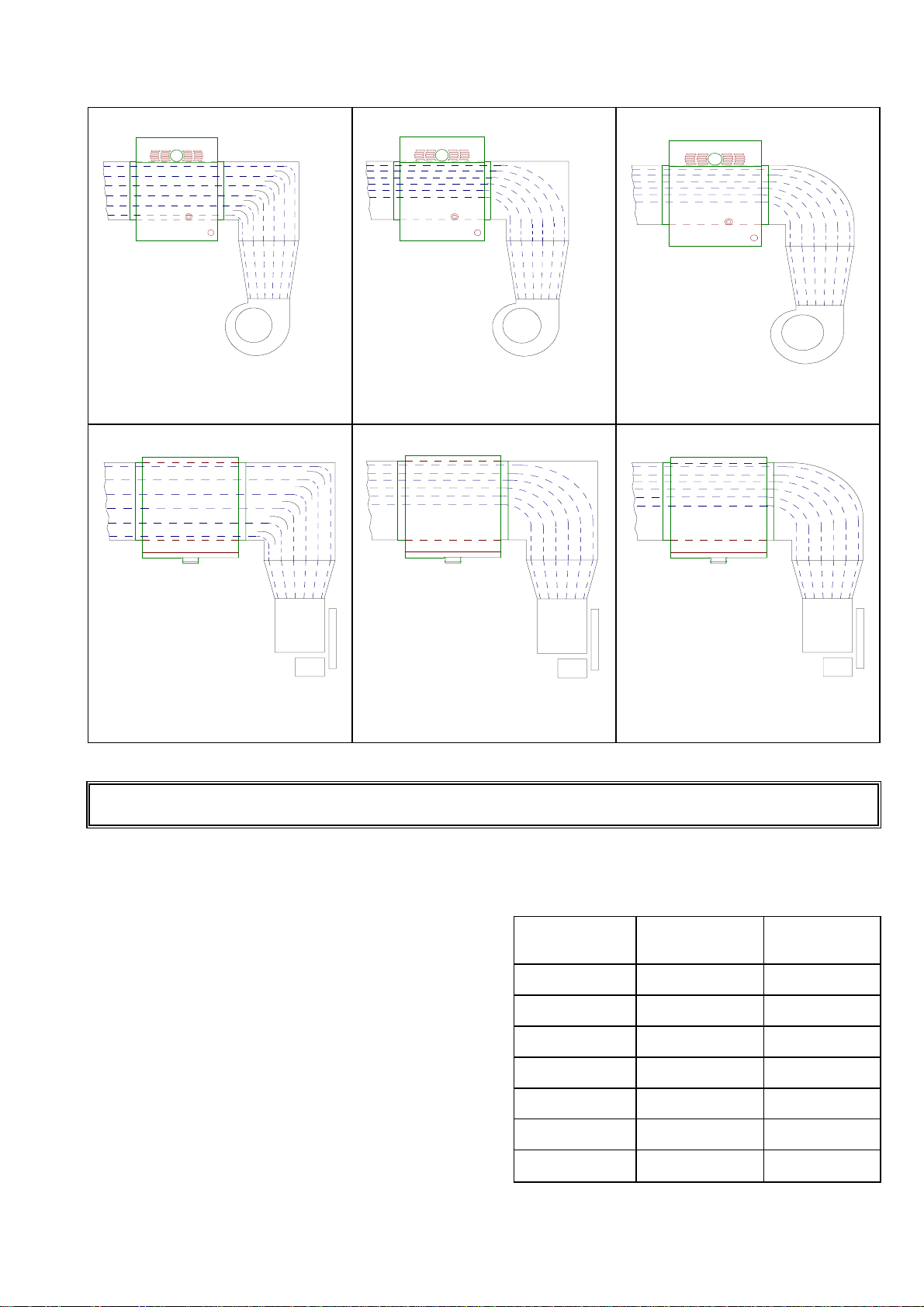
3.10Figure 6 illustrates some of the situations to be
avoided when connecting an air handler to the
appliance. A rule of connecting a straight length of
ducting equal to 3 times an equivalent duct diameter
onto the appliance should be maintained whenever
possible. It is essential that an even air flow is
distributed across the heat exchanger to ensure that
the heat is scrubbed from all the exchanger elements
thus preventing hot spots which will greatly reduce
the working life of the air heater and nuisance burner
shut-down through over heating may occur.
Always avoid installing a centrifugal fan so that the
swirl effect created by the direction of rotation is
counter directive. As well as the effect of uneven air
flows, excessive loss of static pressure is created
resulting in inefficiency of the fan.
Where it is necessary to connect a transition section
as part of the connection then the degree of taper in
any plain should not be greater than 15°. Abrupt
transitions create eccessive pressure drops and lead
to uneven air distribution across the air heater.
3.11Adequate clearance from combustible materials must
be maintained between the appliance and its flue
system.
3.12EURO-X air heaters are open flued natural draught
appliances, it is therefore, important that they are
installed in a draught free zone i.e. away from doors
etc. Consideration must be given to the effects that
any power extraction might have on the buildings
natural pressure condition. The appliance flue will act
as a pressure relief in the event that a negative
pressure exists within the space where the air heater
is installed.
Extract systems must be electrically interlocked with
the air heater controls.

0108X1DHGBEN7
FIGURE 4 SUGGESTED ARRANGEMENTS FOR APPLYING MULTI-HEATER COMBINATIONS

0108X1DHGBEN 8
Figure 5. Recommended procedure and method for connection of ducting and transitions to the air heaters using
a typical proprietary flange system.
5.1 Corner jointing framework 5.2 Cleating between sections to be joined
5.3 Fastening through all members 5.4 Checking alignment and joint worthiness
5.5 Applying gasket seals to prevent air
leakage 5.6 Sectional view of completed joint
Legend: Figure 5.
5.1 Cut and assemble flange into frame to suit opening
5.2 Check dimensions and position on duct spigot
5.3 Ensuring flange is mated correctly
5.4 Checking location after positioning
5.5 Applying sealing gasket
5.6 Sectional view of completed joint

0108X1DHGBEN9
EURO-X..D
Model Heat Input kW Room
Volumes m3
1025 30.28 142
1030 34.94 165
1035 43.26 203
1045 52.00 245
1055 64.67 304
1075 88.96 418
1095 118.70 558
FIGURE 6 AIR HANDLER APPLICATION RECOMMENDATIONS WHEN USING ELBOWS FOR APPLIANCE CONNECTIONS
Elbow with turning vanes from below Square heel elbow from below Round heel elbow from below
GOOD BAD BAD
Elbow with turning vanes from the side Square heel elbow from the side ...Round heel elbow from the side
GOOD BAD BAD
SECTION 4 AIR SUPPLY for COMBUSTION & VENTILATION
4.1 It is essential that sufficient fresh air is provided for
combustion and room ventilation. Most traditional
building constructions have a natural air change rate
of at least 0.5/h. Where it is known that the air
change rate is at least 0.5/h and where the volume
of the heated space is greater than 4.7m³ per kW of
total rated heat input, additional ventilation is not
required.
If the minima volumes stated above exist as table 4.
together with appropriate similar allowances for other
combustion plant that may be installed in the same
space or zone, then additional ventilation is not
required.
4.2 Table 4.:Building volume limits for Reznor EURO-X
Air Heaters based upon 4.7m3per kW of rated heat input
for one air heater only.

0108X1DHGBEN 10
EURO-X
Model Heat input
kW Low level
cm²
1025 30.28 140
1030 34.94 160
1035 43.26 200
≤60 kW 1045 52.00 240
1055 64.70 290
1075 88.95 340
≥60 kW 1095 118.70 410
4.3 Where it is known that the air change rate is less than
0.5/h or where the building volume is less than 4.7m³
per kW of heat input, ventilation grilles must be
provided at low level i.e. below the level of the
appliance flue connection. In cases where doubt
exists over the air change rate additional ventilation
must be provided.
For air heaters of heat input less than
60 kW the total minimum free area shall not be less
than 4.5 cm² per kW of total rated heat input as table
5 below.
For our heaters of heat input 60 kW or more the total
minimum free area shall not be less than 270 cm²
plus 2.25 cm² per kW in excess of the 60 kW rated
heat input.
4.4 Table 5. Air Supply Requirement for Combustion &
Ventilation.
Note : Ventilation grilles must be installed so that air
is drawn directly from outdoors. In the event that
communication from the space where the heater is
installed to outdoors is via another room then the
route to outdoors must be ducted through the
communication area.
The grille velocity for all air supply must not exceed
2.0 m/s. Grilles should be sited where they cannot
easily be blocked or flooded. Notices should be
provided advising about the need to keep air supply
grilles unobstructed.
4.5 Where mechanical ventilation is used it shall be by
mechanical inlet with either mechanical or natural
extraction. Automatic means of control such as
interlocks must be provided.
The function of other ventilation plant in the zone
must be taken into account. At no time should it be
possible to create a negative pressure in the zone as
this will lead to a hazardous situation whereby the air
heater flue will act as a pressure relief.
4.6 EURO-X 1000 D air heaters which are used in the free
blowing mode i.e. without discharge air ducting are
installed within the room to be heated If it is
necessary to install the air heater in a separate room
and blow the air into an adjoining room, then return
air should be ducted to the appliance.
EURO-X D air heaters may be used for fresh air and/or
return air as combined heating/ventilation appliances
within an air handling system.

0108X1DHGBEN11
D
0.5+
D2
2
=
D1
SECTION 5 FLUE SYSTEM
5.1 EURO-X air heaters must be connected to a flue
system venting the products of combustion directly
to outdoors.
Flue systems must be installed in accordance with
the rules in force taking into account the location of
flue termination relative to the construction
elements of the building, i.e. windows, roof levels,
etc., and in accordance with statutory
requirements.
5.2 The products of combustion may reach a
temperature of 230 °C. Reznor recommend that
appliances are connected to individual flues sized in
accordance with the diameter appropriate to the
appliance flue connection socket.
Flues must be terminated with an approved
terminal fitting.
5.3 A minimum length of 2.0 m is required to
ensure a good flue draught condition.
5.4 Where it is necessary to flue more than one
appliance into a common flue as fig.9 then the flue
should be sized in accordance with the following
formula:
Where:
D1 = new flue size required
D2= diameter of largest flue
D3= diameter of additional flue
Never connect an additional flue to a main stack at a
90°angle an inverted Ypiece must be used.
5.5 It is not recommended to install the flue directly into
the appliance flue socket but to use a stopped tee
piece following a bend off of the air heater. This
practice prevents ingress of water into the appliance
and affords the facility to connect to a drain to
evacuate water and condensation should this occur.
Figure 7 shows the method recommended.
5.6 If it is necessary to include horizontal runs of flue
within the system, then the horizontal section of flue
should be installed with a positive rise away from the
appliance of at least 1°or 17 mm per metre run until
the vertical section.
A vertical rise from the appliance to the terminal point
of 2.0 X the horizontal length must be maintained as
indicated in figure 6.
5.7 The use of twin wall flue should be considered if
condensation in the flue system is a possibility.
5.8 Difficult flue systems may incorporate a Reznor
"EUROVENTER".

0108X1DHGBEN 12
Maximum horizontal
run with 1°rise = 1
third of vertical
height
Refer to clause 5.4
page 11 for formula
NOTE: FIGURES 7,8 & 9 DEPICT EURO-X 1000 S AIR HEATERS SAME FLUE DATA APPLIES FOR EURO-X
1000 D
Figure 7. RECOMMENDED FLUE CONNECTION Figure 8. HORIZONTAL FLUE CRITERIA
Figure 9. COMMON FLUE SYSTEMS

0108X1DHGBEN13
SECTION 6 GAS CONNECTION
6.1 Connection to a gas service may only be carried by
suitably qualified persons. The gas installation must
comply with the rules in force using materials
appropriate for gas service installations.
6.2 Check that the gas category is in accordance with the
data described on the air heater.
6.3 An adequate gas supply sized to provide the dynamic
pressure for the volume required by the air heater(s)
is essential to maintain the nominal heat input.
6.4 A 90°action gas service tap and, to facilitate
servicing, a disconnect union fitting must be provided
adjacent to the appliance, see figure 10.
6.5 Ensure that a gas service includes a filter and has
been tested and purged in accordance with prescribed
practice prior to commissioning and taking the air
heater into service.
Fig. 10 GAS CONNECTION DETAIL
NOTE : Gas tap must be fitted to fall closed !
WARNING: NEVER use a FLAME to test for GAS Soundness !!!
SECTION 7 ELECTRICAL CONNECTION
THE CRITERIA IN SECTION 6 MAY BE SUPERSEDED BY AN AIR HANDLER MANUFACTURER. CLAUSES 7.3, 7.4 &
7.6 MUST HOWEVER BE OBSERVED
7.1 The Electrical installation may only be carried out by
suitably qualified persons observing the rules in
force.
7.2 Check that the electrical specification is in
accordance with the specified data on the air heater.
A unique appliance wiring diagram is supplied as a
separate document attached to this one, plus an
additional copy is attached to the air heater.
7.3 These appliances must be earthed.
7.4 A separate lockable electrical isolator for each heater
must be provided adjacent to the appliance and in
sight of the service access panel. The isolator must
have a contact separation of at least 3.0 mm on all
poles.
7.5 Ancillary controls are required to provide timed heat
cycles, room comfort temperature level, frost
protection, override air circulation etc. These are not
included with the appliance and should be ordered
separately.
7.6 Ensure when planning the external appliance control
circuitry, that power will be supplied at all times to
the air heater, even when it is control switched in
the 'heat-off' mode. This is necessary to ensure that
the fan can operate independent of the heating
control. Therefore, Never incorporate automatic
controls that electrically isolate the appliance.
NOTE:
EURO-X 1000 D AIR HEATERS ARE SUPPLIED WITH EXTERNAL CONTROL CIRCUITS BRIDGED. THE AIR
HEATER/S WILL OPERATE CONTINUOUSLY UNLESS THESE ARE REMOVED AND TIME AND TEMPERATURE
CONTROLS SUBSTITUTED FOR THEM
OPEN

0108X1DHGBEN 14
SECTION 8. COMMISSIONING, LIGHTING AND OPERATION
COMMISSIONING
8.1 Normally Reznor Euro-X air heaters do not require
commissioning. Final testing after production ensures
that: If installation has been carried out strictly in
accordance with this document, the appliance is ready
to be taken into service.
8.2 Checks to ensure;
- earth continuity
- resistance to earth
- phase supply to correct terminals
- current rating and fuse value
- correct supply gas pressure
- correct burner gas pressure
- satisfactory & smooth ignition
- flue system is evacuating the products of
combustion to outdoor atmosphere.must be
made.
8.3 Euroventer:
Installations may include a Reznor Euroventer. This
device is an electrically powered fan fitted into the
flue system. Its inclusion will be obvious. When a
Euroventer is fitted the control switching of the air
heater as described in 8.8 is via the Euroventer,
which is operationally proven prior to the burner
controls being activated.
8.4 LIGHTING THERMOELECTRIC
Models EURO-X 1000 D 1025 →
→→
→1045
- Ensure that the air discharge louvres are set to an
open position;
- Turn ON the gas supply to the air heater;
-SwitchON the electricity supply to the air heater;
- Set room thermostat or remote control to an OFF
setting;
- If fitted ensure that a time control is at an ON
setting;
- Observe gas control details from figure 11 set
control to star position:
Using a lighted taper or match depress and hold
the control valve start knob and apply light to the
ignition burner. When the ignition burner has lit,
hold control for 30 seconds. Ignition burner
should remain alight when released. Turn knob to
"Flame" position.
NOTE:
If ignition burner has not lit wait five minutes and
repeat the lighting procedure
- Having established the ignition burner set control
to "Flame" position, appliance operation is now
fully automatic;
- Set room thermostat to call for heat and/or adjust
to the desired comfort level. The pilot burner will
now light the main burner.
- In the event that the pilot flame goes out for any
reason it is important to wait five minutes before
attempting to relight the gas due to the possibility
of main gas flowing from the main burner if the
thermocouple has been energised.
- To stop the burner, put the control knob to the
OFF position as indicated in figure 11. It must be
noted there is a security interlock which prevents
relighting for one minute.
Figure 11. GAS CONTROL
TYPE EURO-X 1000 D 1025 →
→→
→1045
Legend figure 11:
1 Control knob
2 Governor
3 Inlet gas pressure test point
4 Burner pressure test point
5 Pilot gas throttle screw
6 Main burner electrical connection
7 Gas inlet
8 Gas outlet
9 Pilot gas line connection
10 Thermocouple connection
8.5 LIGHTING THERMOELECTRIC
Models: EURO-X 1000 D 1055 →
→→
→1095
- Ensure that the air discharge louvres are set to an
open position;
-SwitchOFF the electricity supply to the air
heater;
- Turn ON the gas supply to the air heater;
- Set room thermostat to OFF or its lowest setting;
- Observe gas control details from figure 12 note
start gas position;
- Using a lighted taper or match, depress the
control valve start button and apply light to
ignition burner. Keep start button depressed for
± 20 seconds after the ignition burner has lit;
- Close burner compartment access panel/ door;
-Switch ON the electricity supply to the air heater
- adjust room thermostat to desired temperature or
adjust other external controls to requirements of
timing and temperature.

0108X1DHGBEN15
Important:
If pilot flame fails to light or goes out for any reason
allow 3 minutes before re-lighting. This time must
also be allowed before re-ignition if there is a failure
of the main burner for any reason because gas can
escape from the main burner whilst the
thermocouple is energised.
8.6 To turn off the air heater;
a) For short periods;
- Adjust room thermostat to lowest setting or
switch OFF other external controls;
b) for extended periods;
- Follow a) above and then;
- Turn OFF gas control valve figure 12;
-SwitchOFF electricity supply to the air heater
after the air circulation fan has stopped.
Caution:
The gas service tap to the air heater must not be
turned off except in emergencies or for appliance
servicing purposes or for prolonged periods of shut
down of the air heater.
Figure 12. GAS CONTROL
TYPE EURO-X 1000 D 1055 →
→→
→1095
Legend figure 12.
1. Operating button
2. Gas governor
3. Inlet gas pressure test point
4. Outlet/burner gas pressure test point
5. Ignition burner gas throttle screw
6. Main burner electrical connection
7. Gas inlet connection
8. Gas outlet connection
9. Ignition burner gas connection
10. Thermocouple connection
8.7 EURO-X 1000 D Air heaters fitted with optional
Hot Surface Ignition system.
8.7.1 Ensure that the air discharge louvres are set to an
open position;
8.7.2 Switch ON the electricity supply to the air heater;
8.7.3 Turn ON the gas supply to the air heater;
8.7.4 These appliances employ the direct burner ignition
principle. When the external controls call for heat, a
hot surface igniter will be energised and will glow
for ± 15 seconds, after which time the gas valve(s)
will open and the burner will be lit.
8.7.5 If the burner has not lit within 5 seconds, the
electronic flame relay will switch off and lockout will
occur. This will cause the signal lamp to glow within
the reset push-button on the appliance and/or on a
remote control if fitted). After 10 seconds the reset
button on the appliance or the remote control can
be activated in order to reset and restart the
appliance.
8.7.6 Flame failure protection is by the ionisation principle
i.e. the ability of a suitable flame to pass an
electrical current between the igniter and the
earthed burner assembly. To check the flame
current is adequate, remove jumper between
terminal 17 and 18 on the automatic burner control,
connect a DC micro ammeter between the
terminals. Ionisation current should be ≥2µA.
Note: The terminals carry mains voltage when
energised.
8.8 How the EURO-X 1000 D air heater works
EURO-X 1000 D thermoelectric burner control air
heaters operate automatically after the permanent
ignition burner has been lit.
These appliances are fitted with a thermo-electric
flame failure device. External controls (room
thermostat - time switch) operate to provide heat on.
Upon switching to on, the main burner gas valve
opens and the main burner is lit from the permanent
ignition burner.
Models fitted with hot surface ignition systems
operate fully automatically when switched ON and
the remote controls have been set to call for heat.
Simultaneously to being switched ON an electrical
circuit is made to a thermal fan control switch to
operate a heater within the switch.
This plus the heat of the burner causes the switch
contacts close. When hot, at approximately 45°C,
the air circulation fan will switch on and warm air
will be discharged until the burner is switched off.

0108X1DHGBEN 16
Note :
1. The fan will run on after the burner has switched
off to cool the heat exchanger.
2. During periods of extreme cold operating i.e.
morning start up, the fan may switch on and off
for short periods due to the rapid cooling of the
thermal fan switch. This will cease as the
ambient temperature around the air heater
rises.In the event of overheating for any reason,
thermally activated, fail safe overheat controls
operate to protect the air heater. The first control
LC1 switches off the burner and upon cooling
will automatically reset.
The second control, LC3, which switches at a
higher temperature will if activated switch off
the main burner and on thermoelectric models
the ignition burner, thus causing controlled lock-
out. Following this manual intervention is
necessary to restart the air heater by relighting
the ignition burner or
resetting an automatic burner control after the air
heater has cooled and the LC3 control has
automatically reset or on automatic ignition models
can be itself reset, this may take a few minutes
dependent upon the ambient temperature.
8.9 Commissioning may include that of the air handler
appliance into which the EURO-X 1000 D gas heater
is installed. Follow the separate instructions for the
air handler in addition to these.
8.10 Upon completion of the commissioning, ensure the
user or a responsible person is aware of;
a. How to operate air heater;
b. How to operate the air handler
c. The need for maintenance and servicing;
Important
Ensure that these instructions and the user's
instructions are made available for the user and/or
left in a safe place, i.e. attached to the gas service
meter.
END OF COMMISSIONING INSTRUCTIONS

0108X1DHGBEN17
SECTION 9 SERVICING INSTRUCTIONS
9.1 CAUTION:
Inadvertent substitution or replacement of
components similar to those specified or
replacement in a manner contrary to the method
herein described could constitute a hazard.
Servicing work my only be carried out by
appropriately qualified persons.
9.2 Attention:
Before starting to service the air heater turn OFF
the main gas supply to the heater at the service
tap provided. Switch OFF the main electricity
supply to the heater after the air circulation fan
has stopped.
9.3 EURO-X 1000 D air heaters require maintenance
and service at least once a year. More frequent
servicing may be required dependent upon the
environmental circumstances where the air
heater(s) are installed. Advise the user of
recommended service frequency after your
findings during this service. Regular inspection is
recommended initially, especially in dirty areas, to
assess the
servicing requirement frequency. Refer to the
illustrations provided figs. 18 & 19 for component
and visual instruction as a guide to
carrying out service work. Items that require
inspection during servicing are as described below.
FIGURE 13. BURNER ACCESS PANEL REMOVAL
9.4 General :
Generally clean all accessible surfaces including
the outside of the heat exchanger accessible after
removal of the louvre frame and fan assembly.
Heater casing :
Check for damage that could be detrimental to the
correct fitting of panels and affect the correct
working or noise level. Check that all assembly
screws are fastened, replace missing screws.
Check that all panels are fixed in place upon
completion of service and that motors, fans and
guards are fixed securely.
9.5 Heat exchanger :
To be checked when carrying out burner and flue
section work. Inspect heat exchanger where
visible inside by use of an inspection lamp and
mirror and outside when burner, air circulation fan
and louvre frame have been removed.
Look for signs of severe corrosion, splits and
perforations that would indicate a failure. If upon
inspection it is found that the heat exchanger is
excessively dirty or blocked with e.g. soot, it will
be necessary to remove the front portion of the
draught diverter to aid cleaning. This can be
carried out referring to fig. 15.
1. Remove the screws securing the front of the
down draught diverter Key 1 and the side
screws
2. The portion of the down draught diverter may
then be withdrawn through the front slot by
lifting and pulling outwards.
3. To replace reverse above procedure
Remove any deposits with a flexible flue brush.
Remove loosened deposits with a vacuum cleaner.
IF HEAT EXCHANGER IS FOUND TO BE
PERFORATED ADVISE USER NOT TO OPERATE
HEATER UNTIL A REPLACEMENT HAS BEEN
FITTED.
9.6 Burner :
The orifice of a gas injector is machined to
precision limits, do not clean with a hard sharp
object that could damage or enlarge the size.
Remove burner tray carefully see below. Check
main burner rails for soundness. Clean thoroughly
taking particular care to ensure that burner ports
are free from lint and dust.
Check gas injectors for cleanliness and that thread
joints are gas tight. If necessary clean with
acetone.
Do not over-tighten.
9.7 Burner tray removal :
Refer to figs. 14, 18 & 19
1 Disconnect gas supply at the unions below
the inlet gas service tap and adjoining the
gas control valve.
2 Disconnect the wires leading to the gas
valve at the valve terminal end.

0108X1DHGBEN 18
3 Disconnect wires leading to the thermal
overheat cut off device terminals.
4 Unscrew qty. 2 burner tray fixing screws.
5 Withdraw the burner assembly by pulling
from its runners until it is released.
6 To reassemble reverse procedure 1 thru. 5.
FIGURE 14. BURNER ASSEMBLY REMOVAL
9.8 Note :
Appliances for use on propane or butane gas have
an aeration shutter fitted to the burner inlet air
venturi (see fig. 20). This device may also be
fitted to natural gas appliances which have been
converted. The shutter is set and sealed by a
multi- functional sealing plate marked LPG + NG.
Ensure it is correctly reset after any burner
service work is carried out.
9.10 To renew or service the gas valves :
Remove burner rack assembly as described 9.7
above. To dismantle valve from manifold, take
care when using spanners not to damage valve
bodies which are constructed from soft die cast
aluminium. It is necessary to remove the burner
manifold from the burner ribbon tray assembly to
unscrew the gas valve.
FIGURE 15.
DRAUGHT DIVERTER REMOVAL
Legend figure 15:
1. Draught diverter securing screws left and right
hand side.
9.11 Electrical:
Check all visible wiring for damage, check terminal
security.
When removing for service or renewal any
electrical component follow a logical sequence to
ensure that replacement will be correct. Mark
wiring to ensure before disconnection to ensure
that circuits are re-connected correctly.
9.12 Flue system:
Check that flue is in good condition adequately
supported and that the flue and supports are free
from corrosion and that the flue is unobstructed.
Test for a positive updraught when re-
commissioning the appliance by using smoke
introduced into the draught hood slot at the front
of the air heater.
On flue systems fitted with a Reznor Euroventer
refer to the separate instructions supplied with the
Euroventer.

0108X1DHGBEN19
Figure 16.
THERMOELECTRIC IGNITION BURNER DETAILS Figure 17.
HOT SURFACE IGNITER ASSEMBLY DETAILS
9.14 Figure 16 shows the approximate flame pattern of
the ignition burner and its relationship to the flame
proving thermocouple.
NOTE: Location of the spacer rings when replacing
a thermocouple. Ensure that pilot flame plays on
thermocouple hot-tip only, i.e. top of
thermocouple.
9.15 After any service work has been carried out
re-commission the air heater following the steps
outlined in clauses 8.2 and 8.3 of this document.

0108X1DHGBEN 20
Figure 18. COMPONENT PARTS LOCATION THERMOELECTRIC BURNER CONTROLS
Legend figure 18:
1. Electrical and Controls inlet
2. Flue socket
3. Controls fuse
4. Wiring terminals
5. Thermal overheat control LC3
6. Limit control LC1 plus LC2 on models 75 & 95
7. Thermal fan control
8. Ignition burner
9. Thermocouple
10. Burner ribbon
11. Burner manifold with gas jets
12. Burner gas pressure test point
13. Thermocouple connection LC3
14. Multi-functional gas control
15. Thermal overheat control LC3 sensor
16. Inlet gas connection union
17. Main wiring box
Table of contents
Other Reznor Heater manuals

Reznor
Reznor UBX Manual

Reznor
Reznor UDX Installation and operating instructions

Reznor
Reznor V3 Series Guide

Reznor
Reznor RHC 8000(m) RJL Instruction Manual

Reznor
Reznor EBHB Guide

Reznor
Reznor AB175-2 User manual

Reznor
Reznor UBX Series Owner's manual

Reznor
Reznor OH User manual

Reznor
Reznor LDAP Owner's manual

Reznor
Reznor CAUA User manual

Reznor
Reznor RIHL Owner's manual

Reznor
Reznor LCSBD-4 Guide

Reznor
Reznor RIH Series Owner's manual

Reznor
Reznor OH Installation and operating instructions

Reznor
Reznor FT User manual

Reznor
Reznor ML 1511 Guide

Reznor
Reznor EURO-C 4000 RJL User guide

Reznor
Reznor CAUA User manual

Reznor
Reznor ULSA 035(EC) User manual

Reznor
Reznor ADFH Series User manual