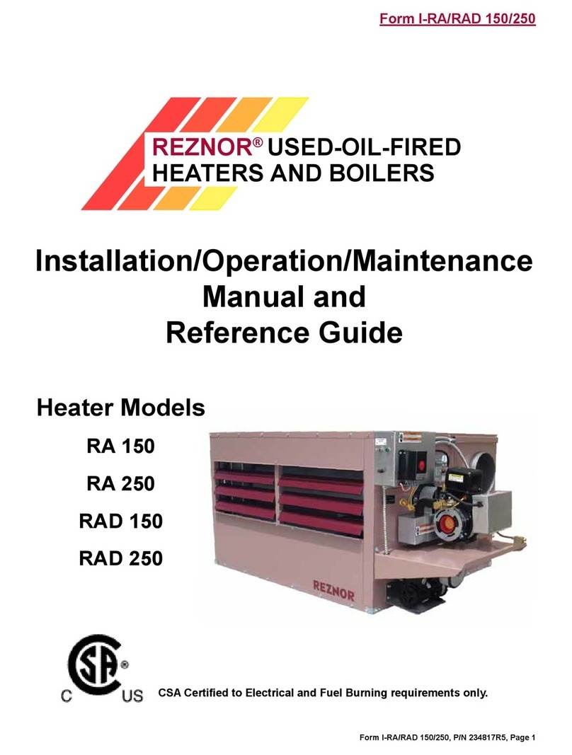
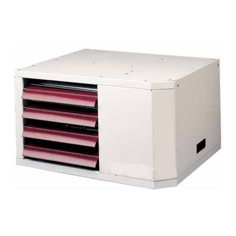
Reznor CAUA User manual

Form O-CAUA, P/N 164772 R4, Page 1
Operation, Maintenance, and Service
Form O-CAUA (Version A)
Obsoletes Form O-CAUA
�
FOR YOUR SAFETY
If you smell gas:
1. Open windows.
2. Don't touch electrical switches.
3.Extinguishanyopename.
4. Immediately call your gas supplier.
Theuseandstorageofgasolineorotherammablevapors
and liquids in open containers in the vicinity of this appli-
ance is hazardous.
WARNING: Improper installation, adjustment, alteration,
service, or maintenance can cause property damage, injury,
or death. Read the installation, operation, and maintenance
instructions thoroughly before installing or servicing this
equipment.
WARNING: Gas-red appliances are not designed for use
inhazardousatmospherescontainingammable vapors or
combustible dust. See Hazard Levels on page 2.
KEEP THIS BOOKLET FOR MAINTENANCE
AND SERVICE REFERENCE.
Model CAUA
with Optional Cased
Cooling Coil
A
G
E
N
C
Y
P
R
O
C
E
S
S
S
T
A
R
T
-
U
P
P
R
O
D
U
C
T
C
U
S
T
O
M
E
R
W
A
R
R
A
N
T
Y
C
O
N
V
E
R
G
E
N
T
Q
U
A
L
I
T
Y
S
Y
S
T
E
M
CQS
CQS
Applies to: Model CAUA
Gas-Fired Indoor
Vertical(Upow),
Power-Vented Heater

Form O-CAUA, Page 2
2. MAINTENANCE A Model CAUA will operate with a minimum of maintenance. To ensure long life
and satisfactory performance, a heater that is operated under normal condi-
tions should be inspected and cleaned at the start of each heating season. If
the heater is operating in an area where an unusual amount of dust, soot, or
other impurities are present in the air, more frequent maintenance is recom-
mended. If the system includes a cooling coil, the coil and condensate drains
should be checked at the beginning of the cooling season.
The paragraphs that follow discuss the components and systems that require
routine inspection/maintenance. At the beginning of each section, there is a
code indicating the main reason why that maintenance procedure is neces-
sary. The legend for that code is shown on the left.
WARNING: If you
turn off the power
supply, turn off the
gas. See Hazard
Levels, Page 2.
HAZARD INTENSITY LEVELS
1. DANGER: Failure to comply will result in severe personal injury or death
and/or property damage.
2. WARNING: Failure to comply could result in severe personal injury or
death and/or property damage.
3. CAUTION: Failure to comply could result in minor personal injury and/or
property damage.
1. General The operation/maintenance/service instructions in this manual apply to Reznor®
Model CAUA upow, separated-combustion, gas-red heater. As with any gas-
burning equipment, regular maintenance procedures are required to ensure
continued safety, reliability, and efciency of the installation.
If service is required, this heater should be serviced only by a qualied service
technician. Service information is this booklet is intended as a guideline for a
qualied gas-red equipment service technician.
2.1 Maintenance
Schedule
The following procedures should be carried out at least annually. Follow the
instructions in Paragraph 2.2.
• Clean the blower and motor. If equipped with a belt drive, check the belt.
• Check the lters.
• Check the gas valve to ensure that gas ow is being shutoff completely.
• Check the burners for scale, dust, or lint accumulation.
• Check the ignitor
1. General ....................................................2
2. MAINTENANCE ....................................2-7
2.1 Maintenance Schedule..................... 2
2.2 Maintenance Procedures.................. 3
2.2.1 Blower and Blower Motor .........................3
2.2.2 Filters ........................................................3
2.2.3 Gas Valve..................................................4
2.2.2 Filters (cont'd)............................................4
2.2.4 Burner Maintenance..................................5
2.2.5 Ignition System..........................................6
2.2.6 Cleaning the Heat Exchanger ...................7
2.2.7 Venter Motor and Wheel ...........................7
2.2.8 Vent or Vent/Combustion Air System ........7
2.2.9 Condensate Drain .....................................7
3. SERVICE - Control Location,
Operation, and Service......................7-15
3.1 Control Locations.............................. 8
3.2 Heater Rating Plate .......................... 8
3.3 Service Procedures .......................... 8
3.3.1 Operating Gas Valve .................................8
3.3.2 Ignition System..........................................8
3.3.3 Combustion Air Proving Switch.................9
3.3.3 Limit Control ............................................10
3.3.4 Flame Rollout Switch ..............................10
3.3.5 Venter Motor and Wheel Assembly .........10
3.3.6 Transformer.............................................11
3.3.7 Blower Motor and Drive...........................12
3.3.8 Blower Compartment Door Switch .........12
3.3.9 Inlet Air Dampers and Controls ..............12
3.4 Troubleshooting.............................. 14
INDEX.........................................................16
REFERENCES ...........................................16
TABLE OF CONTENTS
Form O-CAUA, P/N 164772 R4, Page 3
2.2.1 Blower and
Blower Motor RRemove dirt and grease from the motor and the blower. Use care when
cleaning to prevent causing misalignment or imbalance. If the unit is equipped
with a belt drive, check the belt for signs of wear. Replace if needed.
Check the belt tension. Proper belt tension is important to the long life of the
belt and motor. A loose belt will cause wear and slippage. Too much tension
will cause excessive motor and blower bearing wear. Adjust the belt tension by
turning the adjusting screw on the motor base until the belt can be depressed
3/4" (19mm). (See FIGURE 1.) After correct tension is achieved, re-tighten the
locknut on the adjustment screw and recheck belt alignment.
FIGURE 1 - Check
Belt Tension
Code Reason for Maintenance
S
= Safety (to avoid personal injury and/or property damage)
R= Continued Reliability
E
= Efcient Operation
2.2 Maintenance
Procedures
• Clean the venter
• Clean the heat exchanger both internally and externally.
• Check the vent or vent/combustion air system
• Check the wiring for any damaged wires. Replace damaged wiring.
• If equipped with a cooling coil, check the drain lines. Clean as needed.
NOTE: Use only factory-authorized replacement parts.
2.2.2 Filters RE Check the lters quarterly. Clean or replace as needed. Replace-
ment P/N's for lters are listed here with application by size listed below.
2" Pleated Filters 2" Permanent Filters 2" Disposable Filters
16x16, P/N 104109 16x16, P/N 104103 (Btm Filter Cabinet only)
12x32, P/N 114324 12x16, P/N 114325 16x16, P/N 104101
16x20, P/N 101620 16x20, P/N 101620
1" x 16" x 25" Filters for Inlet Base only (Size 350 and 400 only)
Disposable - P/N 16447; Permanent - P/N 101609; Pleated - P/N 104107
(Applies to a heater
with either an
optional return air
ltercabinet;an
outside air/return
air mixing box with
lters;oraninlet
basewithlters.) Sizes & Quantities of Filters Used in Return Air Filter Cabinet
To replace lters, select replacement P/N's from the list above for type and size
of lters. If using eld-replacement lters, replace with same size and type.
TABLE 1A -
Replacement Filters
for Return Air Filter
Cabinet
For Full Size Filter Cabinet on
Either Side of the Heater For Small Filter Cabinet on
Either Side or Rear of Heater
Size Permanent or Pleated
150, 200, 250, 300 (4) 16x16 - 2" Filters Size CFM FPM 2" Filters
350, 400 (6) 16x16 - 2" Filters Pleated Permanent
For Full Size Filter Cabinet on Rear of Heater
150
1800 375 (2) 12x32 (4) 12x16
Size Permanent or Pleated 2400 500 (2) 12x32 (4) 12x16
150, 200 (4) 16x16 - 2" Filters *3000 625 -- (4) 12x16
250, 300, 350, 400 (6) 16x16 - 2" Filters 200 2400 500 (2) 12x32 (4) 12x16
For Filter Cabinet on Bottom of Heater *3000 625 -- (4) 12x16
Size Permanent, Pleated, or
Disposable Filters *Application requires 2" permanent; do not
use pleated lters.
150, 200 (6) 16x16 - 2" Filters
250, 300 (8) 16x16 - 2" Filters
350, 400 (12) 16x16 - 2" Filters

Form O-CAUA, Page 4
2.2.3 Gas Valve
Single-Stage
Valve
Two-Stage
Valve
1/8" INLET
Pressure Tap
1/8”
Outlet
Pressure
Tap
1/8" INLET
Pressure Tap
1/8”
Outlet
Pressure
Tap
FIGURE 2
2) With the manual valve turned off to prevent ow to the gas valve, connect a
manometer to the 1/8” inlet pressure tap in the valve. NOTE: A manometer
(uid-lled gauge) with an inches water column scale is recommended.
3) With the eld-installed manual valve remaining closed, observe the
manometer for two to three minutes for an indication of gas pressure. No
pressure should be indicated on the manometer.
If the manometer indicates a gas pressure, the eld-installed manual
gas valve must be replaced or repaired before the combination gas valve
can be checked.
4) If the manometer does not indicate gas pressure, slowly open the eld-
installed manual gas valve. After the manometer's indicated gas pressure
has reached equilibrium, close the manual shutoff valve. Observe the gas
pressure. There should be no loss of gas pressure on the manometer. If
the manometer indicates a loss of pressure, replace the combination gas
valve before placing the heater in operation.
WARNING: The operating valve is the prime safety shutoff.
All gas supply lines must be free of dirt or scale before
connecting to the unit to ensure positive closure. See Hazard
Levels, page 2.
Instructions:
1) Locate the
1/8” FPT
INLET pres-
sure tap on
the combina-
tion valve
(See FIGURE
2, right).
2. Maintenance
(cont'd)
2.2 Maintenance
Procedures
(cont'd)
SRemove external dirt accumulation and check wiring connections.
The combination gas valve must be checked annually to ensure that the valve
is shutting off gas ow completely.
TABLE 1B -
Replacement Filters
and Blockoff Plates
for Mixing Box
Sizes and Quantities of Filters (2" Permanent or 2" Pleated only)
and Blockoff Plates Used in the Optional Outside Air/Return Air
Mixing Box
To replace lters, select replacement P/N's from the list on page 3 for type and
size of lters in TABLE 1B. If using eld-replacement lters, replace with same
size and type.
TABLE 1B - Replacement Filter Quantity and Sizes for Mixing Box
Size Filters - (Qty) Size Filter Blockoff Plate
150, 200 (2) 16 x 16; (2) 16 x 20 (1) P/N 123226
250, 300, 350, 400 (6) 16 x 16 (1) P/N 114337
CAUTION: DO NOT
bottom out the gas
valve regulator
adjusting screw.
This can result
in unregulated
manifold pressure
causing excess
overreandheat
exchanger failure.
Sizes and Quantities of Filters (1" only) Used in the Optional Inlet
Base (Option AVA2 for Sizes 350 and 400 only)
Each base requires eight lters (or only six if one side is blocked off). Filters are
1" x 16" x 25"; P/N's for each type of lter are listed in the table on page 3.
2.2.2 Filters (cont'd)

Form O-CAUA, P/N 164772 R4, Page 5
2.2.4 Burner
Maintenance WARNING: Excessive dirt buildup on and inside the burner
ports could cause fuel gas to spill out of the back of the burn-
er tube causing gas odor inside the building. If uncorrected,
fuel spilling out of the back of the burner tube could cause a
reorexplosion.Topreventfuelgasfromspillingfromthe
back of the burners, check the burner ports at least annually
and clean if necessary.
FIGURE 3 - View of
Control Compartment
with Access Panel
and All Sections of
the Burner Cover
Removed (Wires
and tubing are not
illustrated.)
Excessive dirt buildup on and inside the ports on a burner could cause fuel gas
to spill out of the back of the burner tube. Fuel gas spilling out of the back of a
burner tube will cause gas odor inside the building, and if not corrected, could
eventually cause a re/explosion hazard. To prevent fuel gas spilling from the
back of a burner tube, check the burner ports at least annually and clean if nec-
essary. Remove any soot deposits from the burners with a wire brush. Clean
the ports with an aerosol degreaser and/or compressed air. Wipe the inside
of the burner tubes clean. (Cleaning the burners with an aerosol degreaser is
highly recommended as the degreaser will retard future buildup of dirt.)
SInstructions for Burner Rack Removal (See FIGURE 3.)
1. Shut the gas supply off upstream of the combination valve.
2. Turn off the electric supply.
3. Remove the burner compartment door.
4. Disconnect the union and remove the gas pipe from the inlet of the gas valve.
5. Mark and disconnect the electrical wires to the gas valve. Disconnect the ame sensor wire, the
ame rollout switch wires, and the ignitor wire at the burner box cover. Mark and disconnect the
ignitor ground wire at the terminal board.
6. Disconnect the silicone tubing from the static tap on the burner box cover.
7. Remove all burner cover sections. Depending on when the unit was manufactured, there will be
either two or three sections. If two, there will be a right and left section which extend over the front. If
three, there will be right, left, and a separate front section.
8. Remove the screws that attach the manifold to the burner rack. Slide the manifold from the burner
rack. Remove the screws at the ends of the burner rack that attach it to the cabinet. Carefully pull the
burner rack away from the heater.
CAUTION: Use of eye protection is recommended.
Clean the Burner
Rack and Manifold
(requires a wire
brush, cleaning cloth,
an automotive type
aerosol degreaser or
refrigerant coil cleaner,
and compressed air)

Form O-CAUA, Page 6
RThis heater is equipped with a direct spark integrated control system. The
ignition board monitors the safety devices and controls the operation of the
blower and venter motors and the gas valve.
Ignition System Operating Sequence
On a call for heat from the thermostat, the system energizes the venter motor
and goes through a 10-second prepurge. The system veries that the pressure
switch has changed states closing the normally open contactor and that the
high limit is in the closed state.
The gas valve is then energized, and the ignition system provides the high volt-
age spark to the electrode to ignite the main burner gas. Burner ame is elec-
tronically sensed by the control (minimum 1.0 microamps) upon carryover of all
burners. (A separate solid metal probe is used as the ame sensing function. A
low voltage electrical signal is imposed on the metal probe which is electrically
isolated from ground. When the ame impinges on the ame sensing probe,
the ame acts as a conduction path to ground. The ame recties and com-
pletes the DC circuit, and the ignition system acknowledges the ame.)
The blower motor is energized after 30 seconds of ame sensing.
After the thermostat has been satised, the system de-energizes the gas valve,
the venter motor goes through a 45-second post-purge, and the blower motor
remains energized for an additional 135 seconds.
NOTE: This is a three trial system. The unit will lockout for one hour before ini-
tiating another trial for ignition. If the unit fails after one recycle interval, the unit
will go into hard lockout and must be reset by interrupting power or resetting
the thermostat. To initiate another trial for ignition before the one hour interval,
either reset the thermostat or interrupt power to the unit for 30 seconds.
Maintenance: To access the ignition system, follow Steps 1-3 in Paragraph
2.2.4.
Ignitor - On the right side of the burner rack, locate the ignitor. Disconnect
the wire; remove the screw and the ignitor. Clean the ignitor assembly with an
emery cloth.
Spark gap must be maintained to 1/8". See FIGURE 6,page 9.
IMPORTANT: When re-assembling, the brown ground wire must remain
attached to the ignitor.
CAUTION: Due to high voltage on the spark wire and electrode, do
not touch when energized. See Hazard Levels, Page 2.
Flame Sensor - On the left side of the burner rack, locate the ame sensor.
Disconnect the wire; remove the screw and the ame sensor. Clean with an
emery cloth.
Ignition Control - The integrated ignition control module monitors the opera-
tion of the heater including ignition. Do not attempt to disassemble the igni-
tion control module. However, each heating season the lead wires should be
checked for insulation deterioration and good connections.
Proper operation of the direct spark ignition system requires a minimum
amesignalof1.0microampsasmeasuredbyamicroampmeter.
2. Maintenance
(cont'd)
2.2 Maintenance
Procedures
(cont'd)
2.2.4 Burner Maintenance (cont'd)
2.2.5 Ignition System
Inspect the cleaned burner rack for any damage or deterioration. If a burner
has any damage or signs of deterioration, replace it.
Clean the burner orices with air pressure. Do not ream orices.
Re-assemble the heater and test for proper operation.

Form O-CAUA, P/N 164772 R4, Page 7
ETo clean the outer surfaces (circulating air side) of the heat exchanger,
gain access by removing the inspection panels in the ductwork or removing
the ductwork. Use a brush and/or an air hose to remove accumulated dust and
grease deposits.
The inner surfaces of the heat exchanger can be reached for cleaning with the
burner, turbulators and venter assembly removed. Follow instructions in Para-
graph 2.2.4 to remove the burner (See FIGURE 3).
Remove the turbulators (Turbulators are the metal strips inside the heat
exchanger tubes). Clean the inside of the tubes with a long furnace brush or
a heavy wire to which steel wool has been attached. Brush inside each heat
exchanger tube until all foreign material is removed. A ashlight is helpful in
examining the inside of the tubes. Clean turbulator strips, slide into end of
tubes, and re-attach using the screws removed.
If operating with natural gas, there should be no soot deposits. For operation
with propane gas, if sooting exists, check for improper gas manifold pressure
and for obstructions in the vent.
If the unit is installed as a power vent (drawing combustion air from inside the
building) and dirt is found in the tubes indicating a dirty environment, installa-
tion of a separated combustion/venting system should be considered.
RRemove dirt and grease from the motor housing. The venter motor is per-
manently lubricated; do not lubricate. Carefully clean the venter wheel assem-
bly, being cautious not to bend the wheel.
S
R
Check at least once a year. Inspection should include all joints,
seams, and the terminal caps. Clean any screens and grills. Replace any
defective parts.
2.2.6 Cleaning
the Heat Exchanger
CAUTION: Eye
protection is
recommended.
2.2.7 Venter Motor
and Wheel
2.2.8 Vent or Vent/
Combustion Air
System
2.2.9 Condensate
Drain ERIf the installation has condensate drains (burner, cooling coil, and/or
ue wrapper),.clean or replace parts as needed. Fill traps.
3. SERVICE -
Control
Location,
Operation, and
Service
WARNING: Service work on this heater should only be done
by a qualied gas service technician. The service informa-
tion and the troubleshooting guides are intended as an aid to
aqualiedservicetechnician.
WARNING: Should overheating occur, or the gas supply fail
to shut off, turn off the manual gas valve to the appliance be-
fore shutting off the electrical supply.
WARNING: Do not use this appliance if any part has been un-
derwater.Immediatelycallaqualiedservicetechnicianto
inspect the appliance and replace any gas control which has
been under water.
WARNING: If you turn off the power supply, turn off the gas.
See Hazard Levels, Page 2.

Form O-CAUA, Page 8
Time
Delay
Relay
Ignition Control
Module
(Circuit Board)
Terminal Strip
Relay
Contactor
or Starter
Thermostat
Terminal
Strip
Pressure
Switch
Transformer
FIGURE 4 - Control
Locations in
the Electrical
Compartment
(Remove the control
compartment access
panel)
3.1 Control
Locations
To service this heater, it is necessary to understand the normal operating functions of
the heater controls. Refer to FIGURE 4 to identify and locate the controls.
3.2 Heater Rating
Plate
The heater rating plate is a quick reference for information about a heater
and its installation requirements. In addition, the Serial No. on the rating plate
identies components used in manufacturing that specic heater. The serial
number is coded to identify the gas valve and ignition type that was installed
on the heater at the time of manufacture. This information is required if service
and/or replacement parts are required.
Follow the example below to decode the heater Serial No.
Example: Heater Serial No. BIC78Q3N12345
BIC 78 Q3 N 12345
Month and Year Safety Pilot Code Type of Type of Consecutive
of Manufacture (Type of Ignition) Valve Gas* Number
* N = Natural Gas; L = Propane Gas
NOTE: In addition to the
rating plate, each heater
has a "Replacement
Parts Label" attached that
identies parts specic to
that heater, as well as the
Model and Serial No. of
the heater.
IMPORTANT: The serial number code can only identify the original equipment.
Before servicing, check for a gas conversion label.
When inquiring about replacement parts, always provide the complete Model
No. and Serial No.
3.3.1 Operating Gas
Valve
Function: The gas valve automatically controls the gas ow to the main burn-
ers and regulates the gas pressure.
Service: The valve has no eld-repairable parts. Carefully remove external dirt
accumulation from the valve and check wiring connections.
Refer to Form I-CAUA, Paragraph 6.1, for instructions on checking manifold
pressure.
The gas valve must be checked annually to ensure that the valve is shutting off
gas ow completely; see Maintenance Paragraph 2.2.3.
Gas
Valve
3.3 Service Procedures
3.3.2 Ignition System Function: The heater is equipped with a direct-spark integrated control sys-
tem. The system monitors the safety devices and controls the operation of the
blower and venter motors and the gas valve.
Control Module: The control module is an integrated board located in the
control compartment. Supply and control wiring connects into the control mod-
ule. The module has an LED troubleshooting light which identies operating
problems. The control module also acts as a fan control energizing the fan 30
3. SERVICE - Control Location, Operation, and Service (cont'd)

Form O-CAUA, P/N 164772 R4, Page 9
FIGURE 5 - Integrated
Ignition Control
Module, P/N 195573
Control Status - Green LED
Steady ON Normal Operation, No call for heat
Fast Flash Normal Operation, Call for heat
1 Flash System Lockout, Failed to detect or sustain ame
2 Flashes Pressure Switch in Open Position
3 Flashes High Limit or Flame Rollout Switch Open
4 Flashes Pressure Switch is closed before venter is energized
Steady Off Internal Failure - Replace the ignition control module
Flame Status - Yellow LED
Steady On Flame is sensed
Slow Flash Weak Flame
Fast Flash Undesired Flame
Fan Delay to
OFF Switch (DIP
Switch Settings -
selected prior to
call for heat)
SW1 SW2 Fan Delay To OFF (seconds)
OFF OFF 120
OFF ON 90
ON OFF 160 (Factory Preset)
ON ON 45
Ignitor Connection
seconds after ignition and delaying fan shutdown for 160 seconds after the gas
valve closes. See FIGURE 5 for LED codes and fan delay dip switch settings.
NOTE: This control is on units manufactured beginning 3/09. To replace an
ignition controller on a unit manufactured prior to 3/09, order kit P/N 258251.
FIGURE 6 -
Spark Gap
Front View
of Ignitor
showing
Spark Gap
Measurement
Ignitor
Flame Sensor: The ame
sensor is located on the left
side of the burner assembly.
Instructions for cleaning and
checking the ame sensor
are included in Paragraph
2.2.5.
Service: The direct spark integrated circuit board is polarity sensitive. If burn-
ers cycle on and off, try switching the power supply leads. The supply connec-
tion made to "L1" on the circuit board must be the "hot" wire.
If it is determined that any of the components of the ignition system require
replacing, use only the factory-authorized replacement parts that are designed
for this heater.
Function: The combustion air proving switch is a pressure sensitive switch
that monitors air pressure to ensure that proper combustion air ow is avail-
able. The switch is single pole/double throw with the normally open contacts
closing when a decreasing pressure is sensed in the system.
Ignitor: The ignitor is located on the right side of the burner assembly. Instruc-
tions for cleaning and checking the ignitor are included in the Paragraph 2.2.5.
The spark gap shown in FIGURE 6 must be maintained.
3.3.3 Combustion Air
Proving Switch
Pressure
Switch On start-up when the heater is cold, the sensing pressure is at the most nega-
tive level, and as the heater and ue system warm up, the sensing pressure
becomes less negative. After the system has reached equilibrium (about 20
minutes), the sensing pressure levels off.
If a restriction or excessive ue length or turns cause the sensing pressure to
be outside the switch setpoint, the pressure switch will function to shut off the
main burners. The main burners will remain off until the system has cooled
and/or the ue system resistance is reduced. The table below lists the approxi-
mate water column negative pressure readings and switch setpoints for sea
level operating conditions.

Form O-CAUA, Page 10
3. SERVICE - Control Location, Operation, and Service (cont'd)
3.3 Service Procedures (cont'd)
Model Size Start-Up Cold Equilibrium Setpoint “OFF” Setpoint “ON”
150 1.45 1.05 .75 .90
200 1.50 1.05 .75 .90
250 1.55 1.10 .75 .90
300 1.60 1.15 .75 .90
350 1.30 1.05 .75 .90
400 1.20 1.00 .75 .90
Function: The limit control is a temperature sensitive safety device that will
shut down the gas valve if a temperature above the setpoint is sensed. The
limit control is an automatic reset type with a capillary sensor. When the tem-
perature drops below the setpoint, the limit control deactivates allowing opera-
tion of the heater. The capillary sensor extends across the heat exchanger
section of the unit sensing the temperature of the discharge air.
TABLE 2 - Pressure
Switch Setpoints
(sea level)
DANGER:Safeoperationrequiresproperventingow.NEVERbypassthecombustion
air proving switch or attempt to operate the unit without the venter running and
theproperowintheventsystem.Hazardousconditionscouldresult.SeeHazard
Levels, Page 2.
3.3.3 Limit
Control
3.3.4 Flame Rollout
Switch
TABLE 4 -Flame Rollout Switch
CAUA Size P/N Setting
150-200 112752 225°F
250-300 121275 275°F
350-400 112752 225°F
3.3.5 Venter Motor
and Wheel Assembly
Service: Check the tubing that connects the pressure switch and the venter.
If the tubing is blocked or deteriorated, clean or replace. Be sure that the con-
nections are tight.
If it is determined that the pressure switch needs replacing, use only the fac-
tory-authorized replacement part that is designed for this heater. For location,
see FIGURE 4, page 7. Never bypass the pressure switch.
TABLE 3 -
Limit Controls
For CAUA Sizes P/N Length Setpoint
150, 200, 350, 400 148588 60" (1524mm) 270°F
250, 300 164792 54" (1372mm) 300°F
Service: If it is determined that the limit control needs replacing, use only the
factory-authorized replacement part that is designed for the size of heater (see
P/N's above). The limit control is accessible in the control compartment. The
capillary sensor can only be reached by removing the ductwork.
Function: The ame rollout switch is a temperature-activated manually reset,
limit switch. The switch is mounted on the side of the burner box in a position
that senses temperature in a central horizontal location at the rear of the burner
assembly.
If the ame rollout switch activates to shutdown the heater, the cause must be
corrected.
Service: If it is determined that the ame
rollout switch needs replacing, use only the
factory-authorized replacement part that is
designed for use on this heater (see P/N's
in the TABLE 4).
Function: The venter assembly provides a metered ow of combustion air
to the burner and exhausts the products of combustion to the outside atmo-
sphere.

Form O-CAUA, P/N 164772 R4, Page 11
Service: If it is determined that the venter motor or wheel needs replacing, use
only the factory-authorized replacement part that is designed for use on this
heater.
Venter Motor Replacement Instructions
Follow these instructions for replacement of the venter motor (Refer to FIG-
URES 7A and 7B). Keep all hardware removed to be used in re-assembling
and installing the replacement parts.
1. If the heater is installed, turn off the gas and the electric power.
2. Remove the control door panel.
3. Disconnect the three venter motor wires at the terminal block connections.
4. Holding the motor, remove the screws (3 or 4) that attach the venter
motor mounting plate to the venter housing. Remove the motor and wheel
assembly from the heater.
5. Refer to FIGURE 7A and follow steps to disassemble the motor and wheel
assembly.
a) With a hex allen wrench, loosen the venter wheel setscrew. Slide the
venter wheel off the shaft.
b) Remove the four nuts holding the motor mounting plate. Remove the
mounting plate.
c) Slid over each bolt is a cylindrical spacer; remove the four spacers.
Remove the support ring.
d) Loosen the setscrew and remove the small fan blade.
6. Re-assemble with the replacement venter motor (NOTE: Check the gasket
on the motor mounting plate; if deteriorated or torn, replace it.):
a) With the blade side closest to the motor (hub away from motor), slide the
small fan blade on to the shaft. Position the blade so that it does not hit
the motor; tighten the set screw to the at side of the motor shaft.
b) Put a spacer over each bolt and slide the motor support ring over all the
bolts. Position the mounting plate with the side with the gasket away
from the motor. Secure the plate with the nuts (hand tighten with a nut
driver; do not use a power tool). Rotate the fan to check for clearance. If
required, loosen the set screw and adjust the position of the fan blade.
c) With the "closed" side toward the motor, slide the venter wheel over the
end of the shaft. Position the wheel with the spacing shown in FIGURE
7B. Tighten the set screw to the at side of the motor shaft. Check
for proper balance. If the wheel is damaged or does not turn properly,
replace it.
7. Install the assembled venter motor and wheel. Follow the wiring diagram to
connect the venter wires. Close the access panel.
Function: The 40VA transformer reduces the supply voltage to a 24-volt circuit
in order to operate the 24-volt controls.
Complete Venter
Motor
and Wheel Assembly
Size 150, P/N 174010
Sizes 200, 250, 300,
P/N 162895
Sizes 350 and 400,
P/N 164542
Refer to Parts
Form P-CAUA
for components.
Motor
Support Ring
Fan
Motor Mounting Plate
Nuts
(4)
Wheel
NOTE: Prior to 10/07,
included four spacers and
more narrow support ring.
FIGURE 7A - Venter
Motor and Wheel
Assembly
3.3.6 Transformer
FIGURE 7B -
Spacing between
the venter wheel
and motor
mounting plate

Form O-CAUA, Page 12
3. SERVICE - Control Location, Operation, and Service (cont'd)
3.3 Service
Procedures
(cont'd)
Transformer Check (requires a volt meter): To verify the 24-volt circuit,
check the operation of the transformer. Set the thermostat to above room tem-
perature. Using a voltmeter, check the voltage between Terminal R on the ther-
mostat terminal strip and the ground terminal on the ignition controller. If there
is no voltage in this circuit, the transformer is not functioning. The service of a
transformer is like that of a light bulb; it is either good or bad and when bad, it
must be replaced.
Service: If replacement of the transformer is necessary, do not substitute any
other transformer. Use replacement transformer IDENTICAL to the factory-
installed models.
IMPORTANT NOTE: Do not short the "hot" side of the transformer to ground
when servicing the heater. Doing so will cause the transformer to fail.
40VA
Transformer
in the Heater
Electrical Box,
P/N 164328
40VA
Transformer
in the Optional
Mixing Box,
P/N 103497
3.3.7 Blower Motor
and Drive
Location/Function: The blower motor and blower are located in the blower
compartment at the bottom of the heater. NOTE: The blower compartment
door is equipped with a safety switch. If the door is not closed, the heater will
not operate.
The function of the motor and drive is to provide airow through the heat
exchanger and supply air to the space. Model CAUA units are equipped either
with a direct-drive or a belt-drive blower and motor.
Size 150 and 200 heaters equipped with direct-drive have one 1HP blower
motor. A Size 150 has a 12-9 blower and a Size 200 has a 12-12 blower. Sizes
250-400 have dual 1HP blower motors and dual 12-9 blowers.
Sizes 150-200 with belt-drive have a single motor and blower; sizes 250-400
have a single motor and dual blowers. Motor ranges in size from 1/4 to 5 HP.
For information on how to adjust the blower speed, see Form I-CAUA, Para-
graph 6.5.
CAUTION: An external duct system static pressure not within the limits
shown on the rating plate, or improper motor pulley or belt adjustment,
may overload the motor. See Hazard Levels, Page 2.
Function: The blower compartment door is equipped with a
safety switch. If the door is not closed securely, the heater will
not operate.
Service: If it is determined that the blower compartment
door switch needs replacing, use only the factory-authorized
replacement part that is designed for use on this heater.
Door Switch,
P/N 116023
Inlet Air Dampers
Location: Dampers and controls are located in the optional outside air/return
air mixing box. (Potentiometer may be remotely located.)
Function: Dampers operate in response to controls. See controls below and
application by option in TABLE 5, pages 13-14.
Service: Clean dampers and controls of dust or dirt.
3.3.8 Blower
Compartment Door
Switch
3.3.9 Inlet Air
Dampers and
Controls
2-Position
Damper
Motor
2-Position Damper Motor
Function: The 2-position damper motor opens and closes the dampers.
Damper position is either on when the unit is operating or is determined by a
two-position enthalpy control.
Service: There is no service required on this motor other than external clean-
ing. If the motor needs replaced, replace with an identical damper motor or
damper motor replacement kit.
For information on
replacing a belt, see
Maintenance Section,
Paragraph 2.2.1.

Form O-CAUA, P/N 164772 R4, Page 13
Modulating
Damper
Motor
Modulating
Damper Motor,
P/N 196302
with Logic
Module
Modulating Damper Motor
Function: The modulating damper motor actuates the dampers in response to
a potentiometer or a mixed air controller. Outside air dampers close when the
heater shuts down.
Service: There is no service required on this motor other than external clean-
ing. If the motor needs replaced, replace with an identical damper motor.
Potentiometer
Function: The potentiometer is a manually set switch used with modulating
dampers to set a minimum outside air damper opening. It is either mounted in
the mixing box or remotely located.
Service: If the potentiometer needs replaced, replace it with an identical
switch.
Return Air Controller
Function: The return air controller senses the temperature of the incoming
return air. On a two-position outside air damper system, it activates the motor
to open and close the outside air damper. On a modulating system, the return
air controller maintains 100% return air until the set temperature is reached at
which point the mixed air controller (with or without potentiometer) controls the
dampers based on the mixed air control setting. When in the heating mode, the
temperature of the "mixed" return and outside air entering a standard Model
CAUA heater must always be 35°F or above. Only when the heater is factory
equipped with makeup air Option AD4 can the entering air temperature be
below 35°F.
Service: If the controller needs replaced, replace it with an identical control.
Mixed Air Controller
Function: The mixed air controller senses the temperature of the air enter-
ing the heater. It automatically operates the damper motor to modulate the
outside and return air dampers based on the temperature setting. When in the
heating mode, the temperature of the "mixed" return and outside air entering
a standard Model CAUA heater must always be 35°F or above. Only when the
heater is factory equipped with makeup air Option AD4 can the entering air
temperature be below 35°F.
Service: If the controller does not function properly, replace it with an identical
control.
Enthalpy Sensor for 2-Position Control
Function: The enthalpy control senses the enthalpy (heat content in a lb of
air) of the outside air entering the heater. When the enthalpy is low, the control
activates the motor to open the outside air damper; when high, it closes the
outside air damper.
Service: If the controller does not function properly, replace it with an identical
control.
Modulating Damper Motor with Logic Module
Function: The modulating damper motor actuates the dampers
in response to enthalpy controls for cooling or a mixed air con-
troller for heating. Outside air dampers close when the heater
shuts down.
Service: There is no service required other than external cleaning. If the motor
or module needs replaced, replace with identical parts.
Potentiometer
Return Air
Controller
Mixed Air
Controller
2-Position Enthalpy
Control

Form O-CAUA, Page 14
TABLE 5 - Application
of Inlet Air Damper
Controls by Option
Codes
3. SERVICE - Control Location, Operation, and Service (cont'd)
3.4 Troubleshooting Check the Ignition Control Module - The integrated ignition control module
monitors the operation of the heater and includes LED signals that indicate
normal operation and various abnormal conditions. If the heater fails to operate
properly, check this signal to determine the cause and/or to eliminate certain
causes. See FIGURE 5, page 8, for signal codes.
Mixing
Box
Option
Motor
Option
Control Option
on W.D. Description Operating
Mode Application
GA1,
GA2,
GA3,
GA4,
GA5,
GA6,
GA7,
GA8,
and
GA9
GB2
None 2-Position
Damper Motor
Heating
only or
Heating and
Cooling
When the unit is operating, the outside air damper is open.
GC3C
2-Position
Damper
Motor with
2-Position
Enthalpy
Control
Cooling
only
To minimize cooling energy consumption and equipment
cycling, when the sensor detects a low enthalpy (heat
content in a lb of air) in the outside air, the control will open
the outside air damper. When the control senses a high
enthalpy in the outside air, the control will close the outside
air damper. Factory setpoint for opening the outside air
damper is 75°F/40% humidity.
GC3C and GC4
Same as above (GC3C only) plus a delay based on return
air temperature. Control delays the opening of the outside
air damper to provide faster cool down of the supply air.
GA4,
GA5,
GA6,
GA7,
GA8,
and
GA9
GB3
GC1A or GC1B
Modulating
Damper Motor
with Manual
Potentiometer
Mounted in
the Mixing
Box (GC1A)
or Remote
(GC1B)
Heating
only or
Heating and
Cooling
To control mixture of inlet air, manually set the
potentiometer to the desired minimum position of the
outside air damper. (See IMPORTANT NOTE left.)
GC1A or GC1B
with GC3A
Same as above (GC1A or GC1B only) plus in heating
mode the dampers are modulated in response to a control
sensing the mixed inlet air temperature. The adjustable
control has a range of 0-100°F; factory setpoint is 35°F.
(See IMPORTANT NOTE left.)
GC1A or GC1B
with GC4
Same as above (GC1A or GC1B only) plus a delay based
on return air temperature. Control delays the opening of
the outside air damper to provide faster cool down (cooling
mode) or warm up (heating mode) of the supply air.
GC1A or GC1B
with both GC3A
and GC4
Includes all of the control functions listed in this section
- a potentiometer (GC1A or GC1B) with both the mixed air
controller (GC3A) and the delay (GC4).
GC3A Modulating
Damper Motor
with Mixed Air
Controller
Heating
only
Dampers are modulated in response to a control sensing
the mixed inlet air temperature. The adjustable control
has a range of 0-100°F; factory setpoint is 35°F. (See
IMPORTANT NOTE left.)
GC3A and
GC4
Above plus a delay based on return air temperature.
Control delays the opening of the outside air damper to
provide faster warm up of the supply air.
GB4
GC3B
Modulating
Damper Motor
with a Logic
Module and
Dual Setpoint
Modulating
Enthalpy
Control
Cooling and
Heating
In cooling mode, damper modulation is controlled by a
modulating enthalpy control. With one sensor measuring
the enthalpy of the outside air and another sensing the
return air, dampers will modulate in response to the control
to maintain the most economic mix in the inlet air (normally
set to maintain between 50-56°F). With two enthalpy
setpoints, damper operation can be interlocked with a time
clock or other device to provide different mix depending
on occupancy or other determining factor. In the heating
mode, damper modulation is controlled by a mixed air
temperature sensor. (See IMPORTANT NOTE left.)
GC3B and
GC4
Above (GC3B only) plus a delay based on return air
temperature. Control delays the opening of the outside
air damper to provide faster cool down (cooling mode) or
warm up (heating mode) of the supply air.
IMPORTANT NOTE: The standard
Model CAUA is designed for a maxi-
mum temperature rise of 75°F. Above
35°F (2°C) outside air temperature, any
percentage of outside air is permitted.
For optimum operation and to prevent
condensation, the mixed air tempera-
ture going to the heat exchanger must
not be below 35°F (2°C).
The inlet air temperature restriction
does not apply to a Model CAUA
ordered with makeup air Option AD4.
A CAUA unit equipped with makeup
air Option AD4 includes stainless steel
components and a ue wrapper con-
densate drain to permit inlet air tem-
perature below 35°F (2°C).
Modulating Enthalpy
Sensor and
Thermistor Sensor
Enthalpy Sensors for Modulating Control
Function: There are two enthalpy sensors, one for outside air and one for
return air. Input from the two enthalpy sensors and the thermistor sensor to the
logic module on the motor allow the motor to modulate the dampers to maintain
the set temperature and control the moisture of the air entering the heater.
Service: If the controls do not function properly, replace with an identical con-
trol.
3.3 Service
Procedures (cont'd)
3.3.9 Inlet Air Dampers and Controls (cont'd)

Form O-CAUA, P/N 164772 R4, Page 15
PROBLEM PROBABLE CAUSE REMEDY
Venter motor will
not start
1. No power to unit. 1. Turn on power, check supply fuses or circuit breaker.
2. No 24 volt power to venter relay. 2. Turn up thermostat; check control transformer output.
3. Integrated ignition control module defective. 3. Replace integrated ignition control module. DO NOT ATTEMPT TO REPAIR
CONTROLMODULE;ITHASNOFIELDREPLACEABLECOMPONENTS.
4. Defective venter motor. 4. Replace venter motor.
Burners will not
light
1. Manual valve not open. 1. Open manual valve.
2. Air in the gas line. 2. Bleed gas line.
3. Door switch open. 3. Close blower compartment door. If door is closed, replace switch.
4. Gas pressure is too high or too low. 4. Set supply pressure at 5" to 14" w.c. for natural gas and 11" to 14" w.c. for propane.
5. No Spark: 5.
a) Loose wire connections a) Be certain all wire connections are solid.
b) Transformer failure b) Be sure 24 volts is available.
c) Incorrect spark gap. c) Maintain spark gap at 1/8".
d) Spark cable shorted to ground. d) Replace worn or grounded spark cable.
e) Spark electrode shorted to ground e) Replace if ceramic spark electrode is cracked or grounded.
f) Burners not grounded f) Make certain ignition control module is grounded to the ignitor.
g) Ignition control module not grounded. g) Make certain ignition control module is grounded to the furnace chassis.
h) Faulty integrated ignition control module h) If 24-volt is available to the integrated ignition control module and all other causes
have been eliminated, replace module. DO NOT ATTEMPT TO REPAIR IGNITION
CONTROL MODULE; IT HAS NO FIELD REPLACEABLE COMPONENTS.
6. Lockout device interrupting control circuit by above
causes.
6. Reset lockout by interrupting control at the thermostat or main power.
7. Faulty combustion air proving switch. 7. Replace combustion air proving switch.
8. Main valve not operating. 8.
a) Defective valve a) If 24 volt is measured at the valve connections and valve remains closed, replace
valve.
b) Loose wire connections b) Check and tighten all wiring connections.
9. Ignition control module does not power main valve. 9.
a) Loose wire connections a) Check and tighten all wiring connections.
b) Flame sensor grounded b) Be certain ame sensor lead is not grounded or insulation or ceramic is not
cracked. Replace as required.
c) Incorrect gas pressure c) Set supply pressure at 5" to 14" w.c. for natural gas and 11" to 14" w.c. for propane.
d) Cracked ceramic at sensor d) Replace sensor.
10. Flame rollout switch open 10.
a) Air blockage through the unit a) Check for heat exchanger or vent pipe blockage.
b) Faulty ame rollout switch b) Replace ame roll out switch.
Burners cycle on
and off
1. Gas pressure is too high or too low. 1. Set supply pressure at 5" to 14" w.c. for natural gas and 11" to 14" w.c. for propane.
2. Burners not grounded 2. Make certain ignition control module is grounded to the ignitor.
3. Ignition control module not grounded. 3. Make certain ignition control module is grounded to the furnace chassis.
4. Faulty integrated ignition control module 4. If 24 volt is available to the integrated ignition control module and all other causes
have been eliminated, replace module. DO NOT ATTEMPT TO REPAIR IGNITION
CONTROLMODULE;ITHASNOFIELDREPLACEABLECOMPONENTS.
5. Faulty combustion air proving switch. 5. Replace combustion air proving switch.
6. Flame sensor grounded 6. Be certain ame sensor lead is not grounded or insulation or ceramic is not
cracked. Replace as required.
7. Cracked ceramic at sensor 7. Replace sensor
8. Incorrect polarity. 8. Reverse 115V line connections at ignition control module.
No heat (Heater
Operating)
1. Incorrect manifold pressure or orices. 1. Check manifold pressure (See Form I-CAUA, Paragraph 6.1).
2. Cycling on limit control. 2. Check airow.
3. Improper thermostat location or adjustment. 3. See thermostat manufacturer's instructions.
Cold air delivered 1. Incorrect manifold pressure. 1. Check manifold pressure (See Form I-CAUA, Paragraph 6.1).
Blower motor
will not run
1. Circuit open. 1. Check wiring and connections.
2. Defective integrated ignition control
module (circuit board).
2. Replace module. DO NOT ATTEMPT TO REPAIR IGNITION CON-
TROLMODULE;ITHASNOFIELDREPLACEABLECOMPONENTS.
3. Defective motor. 3. Replace motor.
Blower motor
turns on and
off while the
burner is
operating
1. Motor overload device cycling on and off.
(See below.)
1. Check motor load against motor rating plate. Replace motor if needed.
2. 3-phase motor rotating in opposite
direction.
2. Interchange two legs of supply connections
Blower motor
cuts out on
overload
1. Low or high supply voltage. 1. Correct electric supply.
2. Defective motor. 2. Replace motor.
3. Static pressure incompatibility. 3. Adjust blower speed or ductwork.
4. Defective bearing. 4. Replace motor.

Form O-CAUA, Page 16
www.RezSpec.com
1-800-695-1901
©2009 Thomas & Betts Corporation, All rights reserved.
Trademark Note: Reznor®is registered in at least the United States.
9/09 Form O-CAUA (Version A)
B
Belt Tension 3
Blower 3
Burner Maintenance 5, 6
Burner Rack Removal 5
C
Combustion Air Proving Switch 9
Condensate Drain 7
Control Locations 8
D
Damper Motor 12
Dampers and Controls 12
Door Switch 12
Drive 12
E
Enthalpy Sensor 13
F
Filter Cabinet 3
Filter Quantity and Sizes for Mixing Box 4
Filters 3
Filters for Return Air Filter Cabinet 3
Flame Rollout Switch 10
Flame Sensor 9
G
Gas Valve 4, 8
General 2
H
HAZARD INTENSITY LEVELS 2
Cleaning the Heat Exchanger 7
I
Ignition Control Module 9
Ignition System 6, 8
Ignitor 9
Inlet Base 4
INDEX L
Limit Control 10
M
Maintenance 2
Maintenance Procedures 3
Maintenance Schedule 2
Mixed Air Controller 13
Mixing Box 4
Motor 3, 12
P
Potentiometer 13
Pressure Switch Setpoints 10
R
Rating Plate 8
REFERENCES 16
Return Air Controller 13
S
SERVICE 7
Service Procedures 8
Spark Gap 9
T
Transformer 11
Troubleshooting 14
V
Vent 7
Venter Motor and Wheel 7, 10
REFERENCES Description............................................................................................Form
Model CAUA Installation Manual.......................................................I-CAUA
Model ACU or Option C Cased Cooling Coil Installation .......... I-CAUA-CC
Optional Discharge Plenum Installation Instructions .............. I-CAUA-DP
Optional Filter Cabinet Installation Instructions....................... I-CAUA-FC
Optional Inlet Air Mounting Base Installation Instructions .......I-CAUA-IB
Optional Mixing Box Installation Instructions .........................I-CAUA-MB
Gas Conversion Instructions ................................................CP-CAUA-GC
Ignition Control Replacement Kit Instructions ...................CP-CAUA-IGN
Replacement Parts .......................................................................... P-CAUA
Other manuals for CAUA
7
Table of contents
Other Reznor Heater manuals

Reznor
Reznor LDAP User manual

Reznor
Reznor CAUA User manual

Reznor
Reznor Euro-T 2530D User manual

Reznor
Reznor V3 Series Guide

Reznor
Reznor CAUA User manual

Reznor
Reznor VSUTE series Installation instructions

Reznor
Reznor LCSBD-4 Guide

Reznor
Reznor BE Series User manual

Reznor
Reznor CA1 User manual

Reznor
Reznor OH User manual