Reznor LDAP Owner's manual

Revision: LDAP-IOM (01-22) 207733-A
DOWNFLOW UNIT HEATER
INSTALLATION/OPERATION/MAINTENANCE
Supersedes: I-LDAP (01-19) PN207733R11
MODEL LDAP
⚠ DANGER ⚠
FIRE OR EXPLOSION HAZARD
• Failure to follow safety warnings exactly could result in serious injury, death, or property
damage.
• Improper installation,adjustment,alteration, service,or maintenance can cause serious injury,
death, or property damage.
• Installation and service must be performed by a qualified installer, service agency, or the gas
supplier.
• Be sure to read and understand the installation, operation, and service instructions in this
manual.
• Do not store or use gasoline or other flammable vapors and liquids in the vicinity of this or
any other appliance.
WHAT TO DO IF YOU SMELL GAS
• Do not try to light any appliance.
• Do not touch any electrical switch; do not use any phone in your building.
• Leave the building immediately.
• Immediately call your gas supplier from a phone remote from the building. Follow the gas
supplier’s instructions.
• If you cannot reach your gas supplier, call the fire department.
DO NOT DESTROY. PLEASE READ CAREFULLY. KEEP IN A SAFE PLACE FOR FUTURE REFERENCE.

2LDAP-IOM (01-22) 207733-A
TABLE OF CONTENTS
GENERAL INFORMATION ............................................................................. 3
References ........................................................................................ 3
Important Safety Information........................................................................... 4
Certification........................................................................................ 4
Warranty .......................................................................................... 4
Installation Codes ................................................................................... 5
Cabinet Configurations ............................................................................... 5
Unit Location....................................................................................... 6
Heater Throw ...................................................................................... 6
Mounting Height Requirements ........................................................................ 7
Hazards of Chlorine ................................................................................. 7
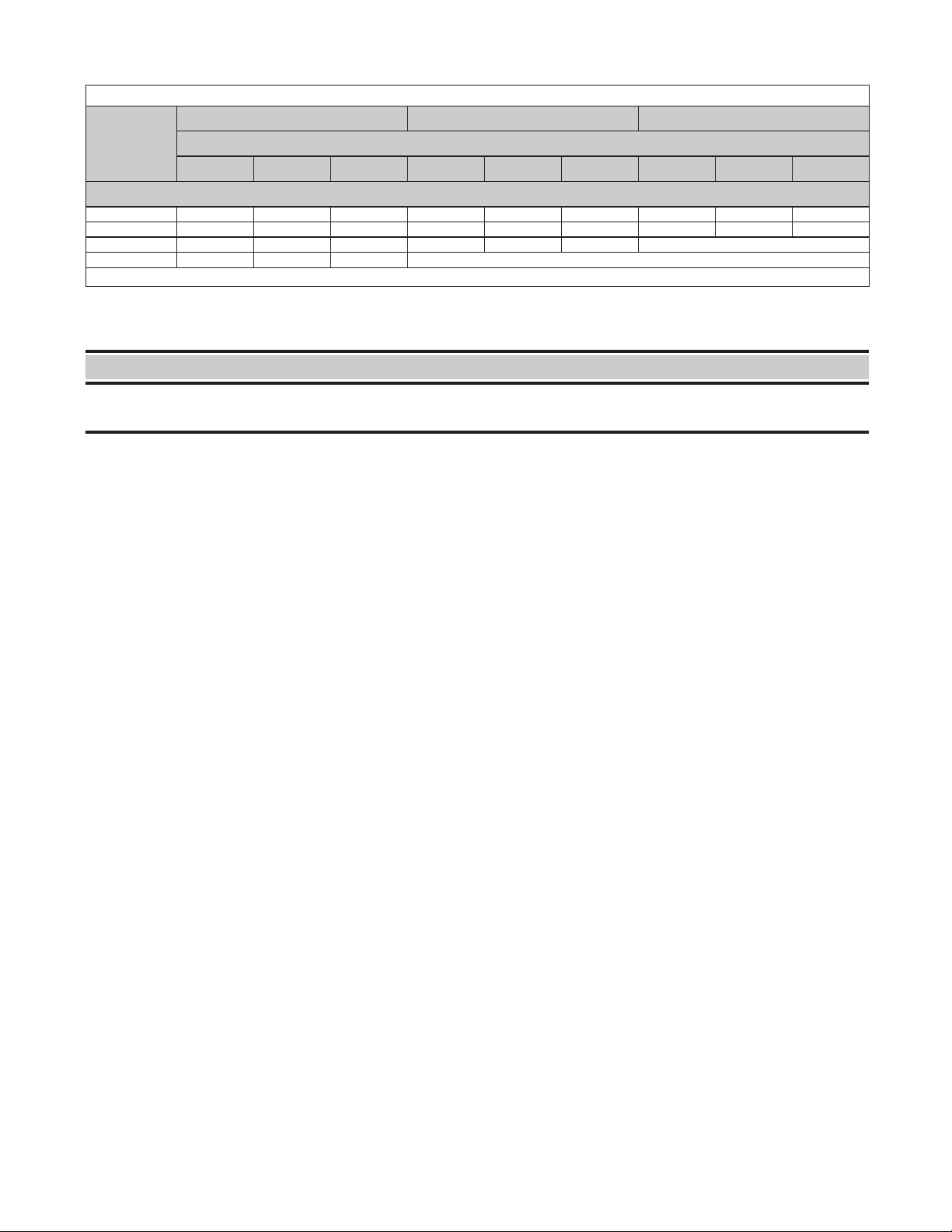
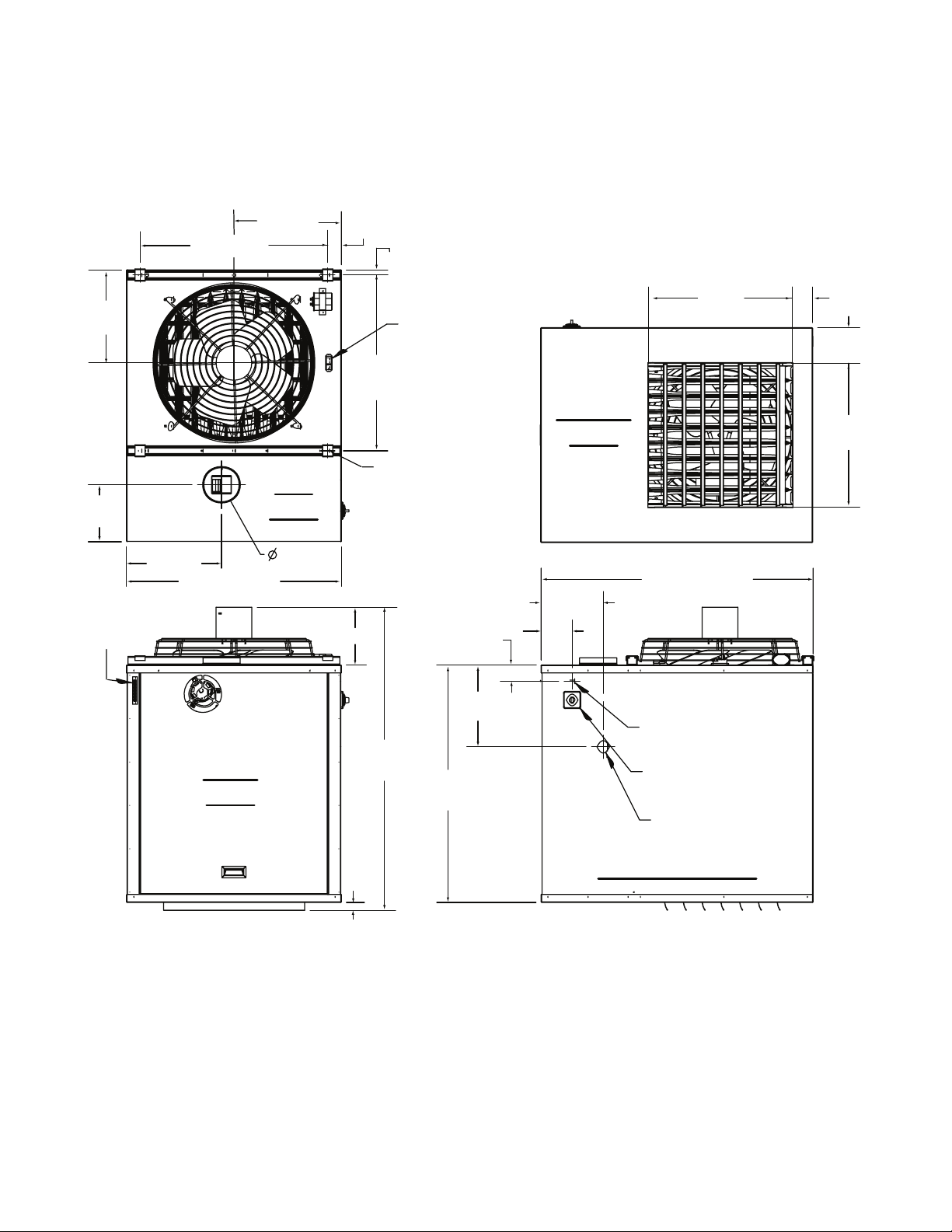
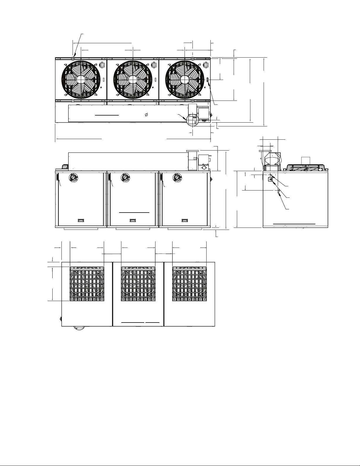
Dimensions ........................................................................................ 8
Clearances .......................................................................................10
Weights.......................................................................................... 10
Combustion Air Requirements ........................................................................11
Acoustical Considerations............................................................................ 12
INSTALLATION .....................................................................................13
Unpacking and Inspection............................................................................13
Pre-Installation Checklist ............................................................................13
Heater Mounting ...................................................................................13
Suspension-Mounting ............................................................................14
Wall-Mounting ..................................................................................14
Piping Connections................................................................................. 15
Gas Supply Pressure............................................................................. 15
Gas Supply Piping............................................................................... 16
Supply Piping Connections ........................................................................ 16
Venting Connections................................................................................ 17
Venting Requirements............................................................................ 18
Vent Pipe Type .................................................................................19
Vent Pipe Size.................................................................................. 19
Vent System Sealing .............................................................................19
Condensation Mitigation ..........................................................................21
Vent System Support Requirements .................................................................21
Vent Terminal (Type of Pipe and Vent Cap) Requirements ...............................................21
Electrical Connections ..............................................................................23
Disconnect Switch Wiring .........................................................................24
Circuit Board Wiring.............................................................................. 24
Fan Motor Wiring................................................................................ 25
Thermostat Wiring ...............................................................................25
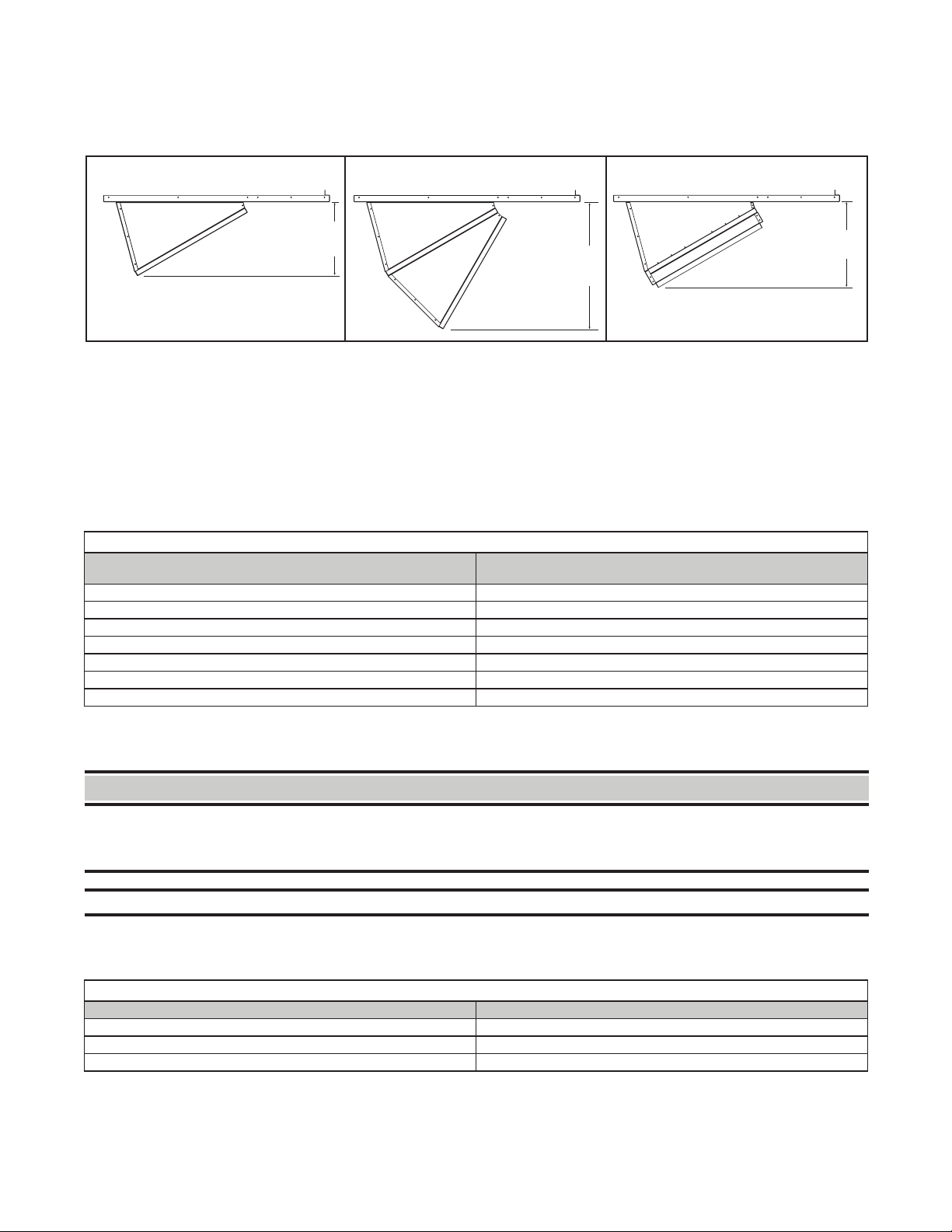
Optional Discharge Air Connections.................................................................... 25
Four-Way Discharge Louvers (Option CD32) .......................................................... 25
Discharge Nozzles (Options CD57, CD58, and CD59) ................................................... 25
CONTROLS ........................................................................................26
Pressure Switches ................................................................................. 26
High Temperature Limit Controls ......................................................................27
Automatic-Reset High Temperature Limit Control.......................................................27
Manual-Reset High Temperature Limit Control ......................................................... 27
Combination Gas Valve ............................................................................. 28
Fan Motor ........................................................................................28
Thermostat .......................................................................................28
Multiple Heater Control (Options CL31 and CL32) .........................................................28
Circuit Board (DSI Control Module) ....................................................................28
Air Destratification Fan Control........................................................................ 28

3
LDAP-IOM (01-22) 207733-A
TABLE OF CONTENTS—CONTINUED
OPERATION ....................................................................................... 29
Pre-Startup Checklist ...............................................................................29
Startup ..........................................................................................30
Operating Sequences ...............................................................................31
Vent System Testing................................................................................ 33
Post-Startup Checklist ..............................................................................34
ADJUSTMENTS..................................................................................... 34
Pressure Switch Replacement ........................................................................34
Measure and Adjust Manifold (Outlet) Gas Pressure ....................................................... 35
Measure and Adjust Manifold Gas Pressure—Elevation ≤2,000 Feet (≤610 Meters) ............................35
Measure and Adjust Manifold Gas Pressure—Elevation >2,000 Feet (>610 Meters)............................37
MAINTENANCE..................................................................................... 38
Service Checklist ..................................................................................39
Maintenance Procedures ............................................................................39
Burner Maintenance ............................................................................. 39
Burner Orifice Maintenance........................................................................ 40
Heat Exchanger Maintenance ......................................................................41
Ignition System Maintenance ......................................................................41
Maintenance of Fan Motor, Fan Blades, and Fan Guard ................................................. 41
Combination Gas Valve Maintenance ................................................................42
Venter Motor and Wheel Assembly Maintenance ....................................................... 43
Pressure Switch Maintenance...................................................................... 44
High Temperature Limit Control Maintenance..........................................................44
Transformer Maintenance .........................................................................44
Fan Control Maintenance ......................................................................... 44
Vent System Maintenance......................................................................... 44
TROUBLESHOOTING ................................................................................ 44
General Troubleshooting ............................................................................44
Unit Troubleshooting Using DSI Control Module .......................................................... 46
INSTALLATION RECORD (TO BE COMPLETED BY INSTALLER)............................................. 48
GENERAL INFORMATION
•This unit heater has been tested for capacity and efficiency so as to provide many years of safe and dependable
comfort providing it is properly installed and maintained. With regular maintenance, this unit will operate satisfactorily
year after year. Abuse, improper use, and/or improper maintenance can shorten the life of the appliance and
create unsafe hazards.
•To achieve optimum performance and minimize equipment failure, it is recommended that periodic maintenance
be performed on this unit. The ability to properly perform maintenance on this equipment requires certain tools
and mechanical skills.
•The instructions in this manual apply only to model LDAP heaters.
References
Table 1. Related Technical Manuals Available from Factory Distributor
Type Form PN*
Replacement parts LDAP-RPL 271892
Gas conversion kit installation LDAP-GC 208881
Heat exchanger gasket kit installation LDAP-HX 209212
High-elevation pressure switch replacement instructions LDAP-DJ20 208081
Vertical louver kit installation LDAP-CD32 208898
Downturn nozzle kit installation LDAP-CD57,58,59 208899
*Also available at www.reznorhvac.com.

4LDAP-IOM (01-22) 207733-A
GENERAL INFORMATION—CONTINUED
Important Safety Information
Please read all information in this manual thoroughly and become familiar with the capabilities and use of your
appliance before attempting to operate or maintain this unit. Pay attention to all dangers, warnings, cautions, and
notes highlighted in this manual. Safety markings should not be ignored and are used frequently throughout to
designate a degree or level of seriousness.
DANGER: A danger statement describes a potentially hazardous situation that if not avoided, will result in severe
personal injury or death and/or property damage.
WARNING: A warning statement describes a potentially hazardous situation that if not avoided, can result in severe
personal injury and/or property damage.
CAUTION: A caution statement describes a potentially hazardous situation that if not avoided, can result in minor
or moderate personal injury and/or property damage.
NOTE: A note provides important information that should not be ignored.
⚠ WARNING ⚠
• Gas-fired appliances are not designed for use in hazardous atmospheres containing flammable
vapors or combustible dust,in atmospheres containing chlorinated or halogenated hydrocarbons,
or in applications with airborne silicone substances.
• Should overheating occur, or the gas supply control system fail to shut off the flow of gas, shut
off the manual gas valve to the unit before shutting off the electrical supply.
• Do not use this appliance if any part has been under water. Immediately call a qualified service
technician to inspect the appliance and replace any gas control that has been under water.
• Installation should be done by a qualified agency in accordance with these instructions. The
qualified service agency installing this heater is responsible for the installation.
• This appliance is not intended for use by persons with reduced physical, sensory, or mental
capabilities or lack of experience and knowledge, unless they have been given supervision or
instruction concerning use of the appliance by a person responsible for their safety.
• Children should be supervised to ensure that they do not play with the appliance.
Certification
•All model LDAP high-bay packaged heaters are design-certified by ITS for use in industrial and commercial
installations.
•All unit sizes are available for use with either natural or propane gas. The type of gas, the input rate, and the
electrical supply requirement are shown on the heater rating plate. Check the rating plate to determine if the heater
is appropriate for the intended installation.
•Unit is certified as a Category III heater.
Warranty
Refer to the limited warranty form in the literature bag provided with the unit. The warranty is void if:
•Wiring is not in accordance with the diagram furnished with the heater.
•The heater is installed without proper clearance to combustible materials.
•The heater is connected to a duct system or if the air delivery system is modified by other than manufacturer-
designed accessories.

5
LDAP-IOM (01-22) 207733-A
Installation Codes
•These heaters must be installed in accordance with local building codes. In the absence of local codes, in the
United States, the heater must be installed in accordance with the National Fuel Gas Code, ANSI Z223.1. Local
authorities having jurisdiction should be consulted before installation is made to verify local codes and installation
procedure requirements.
•Installations in aircraft hangars should be in accordance with ANSI/NFPA No. 409 (latest edition), Standard for
Aircraft Hangars, in public garages in accordance with ANSI/NFPA No. 88A (latest edition), Standard for Parking
Structures, or in repair garages in accordance with ANSI/NFPA No. 88B (latest edition), Standard for Repair Garages.
•If the heater is being installed in the Commonwealth of Massachusetts, installation must be performed by a licensed
plumber or licensed gas fitter.
Cabinet Configurations
These indirect-fired, indoor, downflow packaged heaters are available in three different configurations, as shown
in Figure 1.
Figure 1. Cabinet Configurations
UNIT SIZE 400
UNIT SIZE 800
UNIT SIZE 1200
ONE DOWNFLOW HEATER
ONE HEATER WITH TWO DOWNFLOW HEAT SECTIONS
ONE HEATER WITH THREE DOWNFLOW HEAT SECTIONS

6LDAP-IOM (01-22) 207733-A
GENERAL INFORMATION—CONTINUED
Unit Location
⚠ CAUTION ⚠
• Unit heaters should not be used in an application where the heated space temperature is below
40°F (4°C). Operating under low ambient conditions may cause condensation to form in the heat
exchanger.
• Do not locate the heater where it may be exposed to water spray, rain, or dripping water.
•Refer to the following sections of this manual to determine where to suspend the heater: Heater Throw, Mounting
Height Requirements, Hazards of Chlorine, Dimensions, Clearances, Weights, Combustion Air Requirements,
Acoustical Considerations, and Venting Connections.
Heater Throw
Figure 2 shows throw patterns for all unit sizes in heat mode at high speed. Table 2 lists throw distances for standard
louvers facing one direction and fully open. Throw pattern changes with louver angle, two-way louver direction, and/
or optional four-way louvers.
Figure 2. Heater Throw Patterns (Refer to Table 2)
Mounting
Height Standard Louvers
30° Nozzle
60° Nozzle
Standard
Louvers
30° Nozzle
60° Nozzle
0 = Rear of Heater Discharge
X = DIST
ANCE FROM 0 TO BEGINNING OF FLOOR COVERAGE
Y = DIST
ANCE FROM 0 TO END OF FLOOR COVERAGE
Z = DIST
ANCE FROM 0 TO POINT WHERE AIR VELOCITY DROPS TO <50 FEET (15.2 METERS) PER MINUTE
Y − X = LENGTH OF FLOOR CO
VERAGE

7
LDAP-IOM (01-22) 207733-A
Table 2. Heater Throw Distances
Mounting
Height
Standard Louvers 30-Degree Nozzle 60-Degree Nozzle
Dimension*
X Y Z X Y Z X Y Z
Feet (Meters)
20 (6.1) 5 (1.5) 55 (16.8) 134 (40.8) 40 (12.2) 90 (27.4) 146 (44.5) 70 (21.3) 125 (38.1) 158 (48.2)
30 (9.1) 8 (2.4) 53 (16.2) 121 (36.9) 44 (13.4) 86 (26.2) 133 (40.5) 76 (23.2) 119 (36.3) 145 (44.2)
40 (12.2) 12 (3.7) 49 (14.9) 109 (33.2) 47 (14.3) 81 (24.7) 120 (36.6) —
50 (15.2) 17 (5.2) 45 (13.7) 96 (29.3) —
*See Figure 2.
Mounting Height Requirements
⚠ WARNING ⚠
If touched, the vent pipe and internal heater surfaces that are accessible from outside the heater
will cause burns. Suspend the heater a minimum of 15 feet (4.6 meters) above the floor.
•For best results, the heater should be mounted with certain rules in mind. In general, a unit should be located 15
to 40 feet (4.6 to 12.2 meters) above the floor. Where two or more units are installed in the same room, a general
scheme of air circulation should be maintained for best results.
•Suspended heaters are most effective when located as close to the working zone as possible, and this fact should
be kept in mind when determining the mounting heights to be used. However, care should be exercised to avoid
directing the discharged air directly on the room occupants.
•Partitions, columns, counters, or other obstructions should be taken into consideration when locating the unit heater
so that a minimum quantity of airflow will be deflected by such obstacles.
Hazards of Chlorine
The presence of chlorine vapors in the combustion air of gas-fired heating equipment presents a potential corrosion
hazard. Chlorine is usually found in the form of freon or degreaser vapors. When chlorine is exposed to flame, it will
precipitate from the compound and go into solution with any condensation that is present in the heat exchanger or
associated parts. The result is hydrochloric acid, which readily attacks all metals including 300 grade stainless steel.
Care should be taken to separate these vapors from the combustion process. This may be done by wise location of
the heater with regard to exhausters or prevailing wind directions. Chlorine is heavier than air. Keep these facts in
mind when determining installation location of the heater in relation to building exhaust systems.

8LDAP-IOM (01-22) 207733-A
GENERAL INFORMATION—CONTINUED
Dimensions
Unit dimensions are shown in Figure 3 and Figure 4. Dimensions of optional nozzle(s) on the discharge opening
(option CD57, CD58, or CD59) are shown in Figure 5.
Figure 3. Dimensions—Unit Size 400
Top
View
Bottom
View
Front
View
Right Side View
17-1/8”
(435mm)
30” (762mm)
14-7/8”
(378mm)
9-1/8”
(232mm)
15-1/4”
(384mm)
34-3/8” (873mm)
Hanger Location
1/2-13 Female Thread
28-1/8”
(714mm)
Air
Destratification
Fan Control
7/8” (22mm)
2-1/8” (54mm)
23”
584mm)
3-1/4”
(83mm)
5-5/8”
(143mm)
23”
(584mm)
Discharge Opening
43-1/2” (1105mm)
9-7/8”
(251mm)
5”
(127mm)
2-5/8”
(67mm)
13-1/8”
(333mm)
Line Voltage Connection
Disconnect Switch
1” NPT Gas Connection
38”
965mm)
1-1/4”
(32mm)
48-1/2”
(1232mm)
9-1/4” (235mm)
Thermostat
Connection
6” Flue
Outlet

9
LDAP-IOM (01-22) 207733-A
Figure 4. Dimensions—Unit Sizes 800 and 1200
F V
B V
R S V
T V
Size 800 - 46” (1168mm)
Size 1200 - 80” (2032mm)
Size 800 - 69” (1753mm);
Size 1200 - 103-3/4” (2635mm)
Hanger Locations
1/2-13 Female Thread 11-7/8”
(302mm)
34-3/4” (883mm) 34-3/4” (883mm) 17-1/8”
(435mm)
8” Flue Outlet
7/8” (22mm)
14-7/8”
(378mm)
28-1/8”
(714mm)
Air
Destratification
FanControl
43-1/2”
(1105mm)
46”
(1166mm)
1-5/8” (41mm)12”
(305mm)
9-7/8”
(251mm)
5” (127mm)
2-5/8”
67mm)
13-1/8”
(333mm)
38”
(965mm)
53”
(1346mm)
13-3/4” (349mm)
1-1/4” (32mm)
Line Voltage
Connection
Disconnect
Switch
1-1/4” Gas
Connection
Flue Collection Box Assembly
Thermostat
Connection
Thermostat
Connection
Thermostat
Connection
5-5/8”
(143mm)
3-1/4” (83mm)
11-3/4”
(298mm)
11-3/4”
(298mm)
23”
(584mm)
23”
(584mm)
23”
(584mm)
23”
(584mm)
Discharge
Opening
Discharge
Opening
Discharge
Opening

10 LDAP-IOM (01-22) 207733-A
GENERAL INFORMATION—CONTINUED
Dimensions—Continued
Table 3. Clearances to Combustibles
Heater
Surface Minimum Clearance (Inches (mm))
Top 12 (305)
Flue connector 6 (152)
Front (access panel) 18 (457)
Rear 2 (51)
Disconnect side 18 (457)
Side 2 (51)
Bottom 60 (1524)
Weights
⚠ WARNING ⚠
Check the supporting structure to be used to verify that it has sufficient load carrying capacity to
support the weight of the unit. Suspend the heater only from the threaded nut retainers or with a
manufacturer-provided kit. Do NOT suspend from the heater cabinet.
NOTE: For unit shipping weight, contact an authorized Factory Distributor.
Before installing the heater, ensure that the supporting structure to be used has sufficient load-carrying capacity to
support the weight (refer to Table 4) of the unit.
Table 4. Unit Weights
Unit Size Pounds (kg)
400 375 (170)
800 805 (365)
1200 1195 (542)
Figure 5. Dimensions—Downturn Nozzle Assemblies
Clearances
Units must be installed so that the clearances listed in Table 3 are provided for with regards to combustion air space,
inspection, and service and for proper spacing from combustible construction. Clearance to combustibles is defined
as the minimum distance from the heater to a surface or object for which it is necessary to ensure that a surface
temperature of 90°F (50°C) above the surrounding ambient temperature is not exceeded. Refer to the dimensions
shown in Figure 3, Figure 4, and Figure 5 when determining clearances to combustibles.
CD57 CD58 CD59
14-1/8 INCHES
(360 mm)
24-3/8 INCHES
(618 mm)
16-1/2 INCHES
(419 mm)

11
LDAP-IOM (01-22) 207733-A
Combustion Air Requirements
⚠ WARNING ⚠
• Do not install a unit in a confined space without providing wall openings leading to and from
the space.
• A model LDAP power-vented heater is designed to take combustion air from the space in which
the heater is installed and is not designed for connection to outside combustion air intake ducts.
Connecting outside air ducts voids the warranty and could cause hazardous operation.
•This heater must be supplied with the air that enters into the combustion process and is then vented to the outdoors.
Sufficient air must enter the equipment location to replace that exhausted through the heater vent system. In the
past, the infiltration of outside air assumed in heat loss calculations (one air change per hour) was assumed to be
sufficient. However, current construction methods using more insulation, vapor barriers, tighter fitting and gasketed
doors and windows, weather-stripping, and/or mechanical exhaust fans may now require the introduction of outside
air through wall openings or ducts.
•Under all conditions, enough air must be provided to ensure there will not be a negative pressure condition within
the equipment room or space.
•Requirements for combustion air and ventilation air depend upon whether the unit is located in a confined or
unconfined space. A confined space is defined as a space whose volume is <50 cubic feet per 1,000 BTUh of
the installed appliance input rating. An unconfined space is defined as a space whose volume is ≥50 cubic feet
per 1,000 BTUh of the installed appliance input rating.
•Provide openings (depending on the combustion air source) near the floor and ceiling for ventilation and air for
combustion, as shown in Figure 6 and as listed in Table 5.
NOTE: For further details on supplying combustion air to a confined space, refer to the National
Fuel Gas Code ANSI Z223.1a (latest edition).
Figure 6. Confined Space Combustion Air Openings (Refer to Table 5)
CONFINED
SPACE
A
AB
B
C
C
Table 5. Determining Confined Space Combustion Air Requirements
Letter*Air Source Required Opening Size Calculate Combustion Air
Requirements
A Air inside building 1 square inch free area per 1000 BTUh Add total BTUh of all appliances in
confined space and divide by figures
at left for square inch free area size of
each (top and bottom) opening
Never <100 square inches free area for each opening
B Outside air through duct 1 square inch free area per 2000 BTUh
C Direct outside air 1 square inch free area per 4000 BTUh
*See Figure 6.

12 LDAP-IOM (01-22) 207733-A
GENERAL INFORMATION—CONTINUED
Acoustical Considerations
Refer to the sound level data listed in Table 6 when determining unit location based on acoustical considerations.
Table 6. Technical Data
Parameter Unit of
Measurement
Unit Size
400 800 1200
Input heating capacity BTUh 400,000 800,000 1,200,000
kW 117.1 234.2 351.4
Thermal efficiency % 83
Output heating capacity BTUh 332,000 664,000 996,000
kW 97.2 194.4 291.6
Gas connection inch 1 1-1/4 1-1/4
Vent connection diameter 6 8 8
Control amps (24V)
amp
1.0 2.0 3.0
Full load amps (208V) 5.6 13.6 19.4
Full load amps (230V) 5.5 12.8 18.5
Normal power consumption @ 208V watt 1150 2448 3730
Normal power consumption @ 230V 1230 2597 3959
Discharge air temperature rise °F 55
Air volume, heat @ high speed cfm 5589 11,178 16,768
m3/minute 158 317 475
Discharge air opening area feet23.67 7.35 11.02
meters20.34 0.68 1.02
Outlet velocity, heat @ high speed fpm 1521
m/minute 464
Air volume, destratification @ medium speed cfm 4650 9300 13,950
m3/minute 132 263 395
Outlet velocity, destratification @ medium speed fpm 1266
m/minute 386
Air volume, destratification @ low speed cfm 3250 6500 9750
m3/minute 92 184 276
Outlet velocity, destratification @ low speed fpm 885
m/minute 270
Fan motor*power HP 1
Fan motor*speed rpm 1050
Fan diameter inch 24 24 24
Sound level @ 20 feet (6.1 meters)
dBa 69 72 74
Pascal (Pa) 0.058 0.080 0.100
microbar (µbar) 0.580 0.800 1.000
Sound level @ 25 feet (7.6 meters)
dBa 65 68 70
Pascal (Pa) 0.037 0.051 0.064
microbar (µbar) 0.371 0.512 0.640
Sound level @ 30 feet (9.1 meters)
dBa 62 65 67
Pascal (Pa) 0.026 0.036 0.044
microbar (µbar) 0.258 0.356 0.444
Sound level @ 35 feet (10.7 meters)
dBa 60 62 64
Pascal (Pa) 0.019 0.026 0.033
microbar (µbar) 0.189 0.261 0.327
Sound level @ 40 feet (12.2 meters)
dBa 57 60 62
Pascal (Pa) 0.015 0.020 0.025
microbar (µbar) 0.145 0.200 0.250
*Quantity is one (1) for unit size 400, two (2) for unit size 800, and three (3) for unit size 1200.

13
LDAP-IOM (01-22) 207733-A
INSTALLATION
Unpacking and Inspection
•The unit was test-operated and inspected at the factory prior to crating and was in operating condition.
•It is important to note when uncrating the unit that the crate bottom should be removed after the heater is lifted.
Shipping brackets are attached with cabinet screws. When removing shipping brackets, re-insert ALL screws into
the cabinet.
•If, upon removing it from its crate, the unit has been found to have incurred any damage in shipment, document
the damage with the transporting agency and contact an authorized Factory Distributor. If you are an authorized
Distributor, follow the FOB freight policy procedures.
Pre-Installation Checklist
Check the rating plate for the gas specifications and electrical characteristics of the heater to ensure that they
are compatible with the gas and electric supplies at the installation site.
Read this manual and become familiar with the installation requirements of your particular heater.
If you do not have knowledge of local requirements, check with the local gas company or any other local agencies
who might have requirements concerning this installation.
Before beginning, make preparations for necessary supplies, tools, and manpower.
Locate the hardware kit supplied with the heater. The plastic bag contains spring nuts, hex nuts, U-shaped
fittings, lockwashers, louvers, and compression springs.
Ensure that all shipped-separate options that were ordered are at the installation site. Shipped-separate items
could include a vent cap, louvers, nozzles, hanger kit, a manual shutoff valve, a thermostat, multiple heater
controls, high-temperature tape, and/or a high-elevation conversion kit.
Heater Mounting
⚠ WARNING ⚠
• Before installing the heater,check the supporting structure to be used to verify that it has sufficient
load-carrying capacity to support the weight (refer to Weights section) of the unit.
• The heater must be level for proper operation. DO NOT place or add additional weight to a
suspended heater.
⚠ CAUTION ⚠
• When the heater is lifted for suspension, support the bottom of the heater with the crate bottom.
If the bottom is not supported, damage could occur.
• Before suspending or wall-mounting the heater, ensure that all screws used for holding shipping
brackets have been re-installed in the cabinet.

14 LDAP-IOM (01-22) 207733-A
INSTALLATION—CONTINUED
Heater Mounting—Continued
Suspension-Mounting
• Suspending the heater using threaded rods (see Figure 7, DETAIL A):
a. Install spring nuts in strut that is attached to top of unit.
b. Lock 1/2-13 threaded rods (recommended maximum length is 6 feet (1.8 meters) to heater using U-shaped
fittings, lockwashers, and hex nuts.
• Suspending the heater from 1-inch pipe using swivel connectors (option CK10, see Figure 7, DETAIL B):
a. Install spring nuts in strut that is attached to top of unit.
b. Lock swivel connectors to heater using U-shaped fittings, lockwashers, and hex nuts.
Figure 7. Suspension-Mounting
Wall-Mounting
The heater may be attached to a wall. Place supports as shown in Figure 8 and comply with all of the following
guidelines:
•Mounting is the responsibility of the installer. Verify that the supporting structure has sufficient load-carrying capacity
to support the weight (refer to Weights section).
•Prior to installation, ensure that the method of support is in agreement with all local building codes. Check for
service platform requirements.
•Maintain a 2-inch (51 mm) minimum clearance from the discharge air openings to structural supports. Additional
clearance will be required if an optional nozzle is to be field-installed.
•Determining the need for installing vibration or noise isolation is the responsibility of the installer.
•To prevent potential movement, field-supplied angles must be placed around the perimeter of the heater to anchor
it to the structural supports.
•Structural supports must be placed as shown in Figure 8 to prevent damage to the heater.
•All structural supports must be noncombustible materials.
THREADED
ROD
SWIVEL
CONNECTOR
HEX NUT
LOCKWASHER
SPRING NUT
U-SHAPED
FITTING
STRUT
HEX NUT
LOCKWASHER
SPRING NUT
U-SHAPED
FITTING
STRUT
DETAIL A DETAIL B

15
LDAP-IOM (01-22) 207733-A
Figure 8. Wall-Mounting
Piping Connections
Gas Supply Pressure
The unit is equipped for a maximum gas supply pressure of 1/2 psi, 3.5 kPa, or 14 IN WC.
NOTES:
Supply pressure higher than 1/2 psi requires the installation of an additional service regulator
external to the unit.
PRESSURE TESTING SUPPLY PIPING
• Test pressures above 1/2 psi—disconnect the heater and manual valve from the gas supply line
to be tested. Cap or plug the supply line.
• Test pressures below 1/2 psi—before testing, close the manual valve on the heater.
GAS CONVERSION
• Gas conversion kits are available for changing from propane to natural gas or natural gas to
propane. A factory-authorized conversion kit MUST be used.
All dimensions are measured from centerlines of field-supplied structural supports
Model LDAP 800
(2 heat sections)
Front View
Field-Supplied
Mounting Angles
(MUST be on all
four sides of the
heater.)
Model
LDAP 400
(1 heat
section)
Front View
Model LDAP 1200
(3 heat sections)
Front View
Wall
Side View
Dimensions are
centerline of the
mounting angles
and apply to all sizes.

16 LDAP-IOM (01-22) 207733-A
INSTALLATION—CONTINUED
Piping Connections—Continued
Gas Supply Piping
⚠ DANGER ⚠
• All components of a gas supply system must be leak tested prior to placing equipment in service.
NEVER TEST FOR LEAKS WITH AN OPEN FLAME. Failure to comply could result in personal
injury, property damage, or death.
• The combination gas valve is the prime safety shutoff. All gas supply lines must be free of dirt
or scale before connecting the heater to ensure positive closure.
• Pipe joint compounds (pipe dope) shall be resistant to the action of liquefied petroleum gas or
any other chemical constituents of the gas being supplied.
•All piping must be in accordance with requirements outlined in the National Fuel Gas Code ANSI/Z223.1 (latest
edition).
•Gas supply piping installation shall conform with good practice and with local codes.
•Support gas piping with pipe hangers, metal strapping, or other suitable material. Do not rely on the heater to
support the gas pipe.
•The heater is orificed for operation with natural gas having a heating value of 1,000 (±50) BTU per cubic foot or
with propane gas having a heating value of 2,500 (±100) BTU per cubic foot. Sizing of gas supply lines depends
on piping capacity and is based on cubic feet per hour based on a 0.3 IN WC pressure drop, a 0.6 specific gravity
for natural gas at 1,050 BTU per cubic feet, and a 1.6 specific gravity for propane at 2,550 BTU per cubic feet. If
the gas at the installation does not meet this specification, consult the factory for proper orificing.
•Variables for sizing gas supply lines are listed in Table 7. When sizing supply lines, consider possibilities of future
expansion and increased requirements. Refer to National Fuel Gas Code for additional information on line sizing.
Table 7. Gas Supply Line Sizes
Length of
Pipe (Feet)
Diameter of Pipe (Inches)
1 1-1/4 1-1/2 2 2-1/2
Natural
Gas Propane Natural
Gas Propane Natural
Gas Propane Natural
Gas Propane Natural
Gas Propane
Cubic Feet per Hour
20 350 214 730 445 1100 671 2100 1281 3300 2013
30 285 174 590 360 890 543 1650 1007 2700 1647
40 245 149 500 305 760 464 1450 885 2300 1403
50 215 131 440 268 670 409 1270 775 2000 1220
60 195 119 400 244 610 372 1105 674 1850 1129
70 180 110 370 226 560 342 1050 641 1700 1037
80 170 104 350 214 530 323 990 604 1600 976
90 160 98 320 195 490 299 930 567 1500 915
100 150 92 305 186 460 281 870 531 1400 854
125 130 79 275 168 410 250 780 476 1250 763
150 120 73 250 153 380 232 710 433 1130 689
175 110 67 225 137 350 214 650 397 1050 641
200 100 61 210 128 320 195 610 372 980 598
Supply Piping Connections
⚠ CAUTION ⚠
IMPORTANT: Two pipe wrenches are required when installing gas piping. The gas pipe that is
supplied with the heater MUST be held with a pipe wrench to prevent damage to the heater.

17
LDAP-IOM (01-22) 207733-A
•Install a ground joint union and manual shutoff valve upstream of the unit control system, as shown in Figure 9.
•The 1/8-inch plugged tapping in the manual shutoff valve in Figure 9 provides connection for a supply line pressure
test gauge.
•The National Fuel Gas Code requires the installation of a trap with a minimum 3-inch drip leg (see Figure 9). Local
codes may require a drip leg longer than 3 inches (typically 6 inches). To permit burner removal, this drip leg must
extend beyond the edge of the heater.
•Leak-test all connections by brushing on a leak-detecting solution. Bleed trapped air from gas lines as needed.
•The gas connection is made at the pipe nipple that extends outside the cabinet, as shown in Figure 9. Gas
connection sizes are listed in Table 8.
Table 8. Gas Connection Sizes
Unit Size Natural Gas Propane
Connection (Inches)*
400 1 1
800, 1200 1-1/4 1-1/4
*Connection size for a standard unit (not gas supply line size).
Figure 9. Gas Connections
Venting Connections
⚠ DANGER ⚠
• Each heater requires its own individual vent pipe run and vent cap. Manifolding of vent runs can
cause recirculation of combustion products into the building. Failure to comply could result in
severe personal injury or death and/or property damage.
• If this heater is replacing an existing heater, be sure that the vent is sized properly for the heater
being installed and that the existing vent is in good condition.
• A properly sized vent system is required for safe operation of the heater. An improperly sized
vent system can cause unsafe conditions and/or create condensation.
• Do not intermix different vent system parts from different manufacturers in the same venting
system.
• Do not vent into an existing gravity vent or chimney.

INSTALLATION—CONTINUED
Venting Connections—Continued
Venting Requirements
•These power-vented heaters are designed to operate safely and efficiently with either a horizontal or vertical vent.
Comply with the specific requirements and instructions.
•Installation should be done by a qualified agency in accordance with these instructions. The qualified service
agency installing this system is responsible for the installation.
•Venting must be in accordance with local codes and with the National Fuel Gas Code Z223.1. Local requirements
supersede national requirements.
•Model LDAP heaters are certified as Category III heaters. Refer to Table 9 for a list of Category III vent manufacturers.
18 LDAP-IOM (01-22) 207733-A
Table 9. Category III Vent Manufacturers
Manufacturer Model(s) Diameter
(Inches)
CaptiveAire Systems 2V-Type BH —
Cheminee Lining E Inc. IPP, HEP, HEPL, HEPLA, HEPL1, and HEPL2 6–48
Cleaver-Brooks Inc. CBH, CBHL, CBHL2, CBHLA, and CBHL1
DuraVent Inc.
FasNSeal fixed blade damper assembly 4–18 (ID)
FasNseal special gas vent assembly
—
FasNSeal W2 special gas vent system
FasNSmooth chimney liner system for use in masonry chimneys only
FasNSeal CVS special gas vent system and direct vented pellet system
S-Vent and PVP 4 and 5
ENERVEX Inc. EPS and EPS-1 4–48
ECCO Manufacturing Division of
ECCO Heating Products Ltd. SGDW series 3–6
ICC Industrial Chimney Co. VIC 4–24
Industrial Combustion LLC ICH, ICHL, ICHLA, ICHL1, and ICHL2 4–48
Jeremias Inc.
DWKL, SWKL, DWFL, and SWFL 4–36
DWGV double-wall, air-insulated, 1 inch between inner and outer pipe diameter
—DWGV1 double-wall, fiber-insulated, 1 inch between inner and outer pipe diameter
DWGV2 double-wall, fiber-insulated, 2 inches between inner and outer pipe diameter
SWGV single-wall 4–12
Lifetime Chimney Supply LLC Xi1, Xi2, and Xi4 5
METAL-FAB Inc.
CGSW, FCSSW, CG, FCS, FCG-1, and FCS-1 6–24 (ID)
FCGSW, FCG, FCG-1, FCS-3 CORR/GUARD, and FCS-2 CORR/GUARD 6–36 (ID)
CGSW, CG, FCG, 3CGSWHVK, and 4CGSWHVK 4 and 5
Noritz America Corporation N-Vent 4 and 5
Rheem Sales Co. Inc. RTG 3
Security Chimneys International Ltd. Secure Seal Flex chimney lining system 3–12
Selkirk Corporation
Saf-T-CI and Saf-T C1 4, 5, and 6
Saf-T-Vent 3–6 and 8
EZ Seal 3–6
SGV 3, 4, and 5
CI Plus 6 and 8
SC, DGV, EZ Seal Quick Kit, Sel-Vent, and Sel-Vent II 4
IPS316, PS316, and G316 5 and 6
SFL Flue & Chimney DEVON EPS and EPS-1 4–6
The Schebler Co. SSD, ESW, eVent, and eVent PLUS 2 and 4–6
eVent SD 4–6
Sunair Products SADW-2V and SADW-V 4
Tokyo Gas Renovation Co. Ltd. KP and KC 4 and 5
N-Vent 3, 4, and 5
VAN-PACKER CO INC MW, CS, and CSplus 4–6 (ID)
Z-FLEX US INC
SVE and SVEII 3 and 4
SVEIII 2, 3, and 4
SVEIV single-wall and SVEIV double-wall 4, 5, and 6
NovaVent single-wall and NovaVent double-wall
Z-VentBlu single-wall and Z-VentBlu double-wall 3, 4, and 5

19
LDAP-IOM (01-22) 207733-A
Table 10. Vent Pipe Diameters and Lengths
Unit Size
Venter Outlet
Diameter
Vent Pipe
Diameter
Maximum Vent
Length*
Equivalent Straight Length** Venter Outlet
Connection***
90-Degree Elbow 45-Degree Elbow
Inches (mm) Feet (Meters) Inches (mm)
400 6 (152) 6 (152) 45 (13.7) 15 (4.6) 7.5 (2.3) —
7 (178) 60 (18.3) 8 (2.4) 4 (1.2) 6–7 (152–178)
800 8 (203) 8 (203) 50 (15.2) 15 (4.6) 7.5 (2.3) —
10 (254) 45 (13.7) 5 (1.5) 2.5 (0.8) 8–10 (203–254)
1200 8 (203) 8 (203) 50 (15.2) 15 (4.6) 7.5 (2.3) —
10 (254) 45 (13.7) 5 (1.5) 2.5 (0.8) 8–10 (203–254)
*Includes one 90° elbow at venter outlet.
**Add all straight sections and equivalent lengths for elbows—the total combined length must not exceed the maximum vent length.
***Field-supplied taper-type increaser connection required at the venter outlet.
Vent Pipe Type
The type of vent pipe is determined by whether the vent is horizontal or vertical:
• Horizontal: approved for Category III appliance or appropriately sealed 26-gauge or heavier galvanized steel or
equivalent single-wall pipe
• Vertical: approved for Category III appliance, appropriately sealed 26-gauge or heavier galvanized steel or equivalent
single-wall pipe, or if at least 75% of equivalent length of vent run is vertical, double-wall (Type B) vent pipe
Vent Pipe Size
•Use only one diameter of vent pipe on an installation.
•The minimum vent length is 3 feet (1 meter).
•A minimum of 1 foot (0.3 meter) of vertical vent is required on the venter outlet before installing an elbow.
•Vent pipe diameters and maximum vent lengths in Table 10 apply to both horizontal and vertical vents.
Vent System Sealing
Vent system joints depend on the type of pipe being used:
• Category III pipe: follow manufacturer’s instructions for joining pipe sections—connect venter outlet or the vent
cap using secure, sealed joints that follow a procedure best suited to the style of Category III pipe being used.
• Single-wall galvanized pipe (26-gauge or heavier): secure slip-fit connections using sheet metal screws or
rivets—seal all joints and seams inside the building using tape such as option FA1 (PN 98266) or high-temperature
silicone sealant.
• Double-wall Type B vent pipe: join pipe sections in accordance with the pipe manufacturer’s requirement—refer
to the illustrated instructions in Figure 10 to connect double-wall pipe to the heater collar, single-wall pipe, and
vent cap. Work quickly to assemble components before sealant dries.
NOTE: A double-wall pipe run is allowed only if at least 75% of the vent length is vertical.

20 LDAP-IOM (01-22) 207733-A
STEP 1: Place continual 1/4-
inch bead of silicone sealant
around circumference of
single-wall pipe.
STEP 2: Before sealant can dry,
insert single-wall pipe into inner
pipe of double-wall pipe until
bead of sealant contacts inner
pipe to create sealed joint.
STEP 3: Drill three small holes
spaced equally around double-
wall pipe below sealant ring.
Secure joint using 3/4-inch-
long sheet metal screws. Do
not overtighten screws.
Double-
Wall Pipe
STEP 4: Place continual 3/8-
inch bead of silicone sealant
around he circumference of
vent cap collar to prevent any
water inside vent cap from
running down double-wall pipe.
STEP 6: Drill small hole
through vent cap and double-
wall pipe. Secure joint using
3/4-inch-long sheet metal
screw. Do not overtighten
screw.
STEP 5: Before sealant can dry,
insert collar on vent cap as far
as possible inside inner wall of
double-wall pipe. Apply silicone
sealant to fully close any gaps
between vent cap and double-
wall pipe to prevent water from
entering double-wall pipe.
STEP 7: Place continual 1/4-
inch bead of silicone sealant
around circumference of
venter outlet collar.
STEP 8: Before sealant can dry, slide double-wall pipe over collar
so that collar is inside inner pipe. Push double-wall pipe tight to
heater cabinet. Drill three small holes through the pipe and into collar
spaced equally around pipe below sealant ring. Secure joint using
3/4-inch-long sheet metal screws. Do not overtighten screws.
Figure 10. Instructions for Attaching Double-Wall Type B Vent Pipe to Single-Wall Pipe
INSTALLATION—CONTINUED
Venting Connections—Continued
Vent System Sealing—Continued
Other manuals for LDAP
2
Table of contents
Other Reznor Heater manuals

Reznor
Reznor OH User manual

Reznor
Reznor BE Series User manual

Reznor
Reznor AB-2 Series Supplement

Reznor
Reznor EBHB User manual

Reznor
Reznor RHC 8000 RJL User guide

Reznor
Reznor RIH Series Owner's manual

Reznor
Reznor RIH Owner's manual

Reznor
Reznor UDAP Guide

Reznor
Reznor UDSBD-4E Guide

Reznor
Reznor FT User manual

Reznor
Reznor ST 2 Series Guide

Reznor
Reznor UEAS User manual

Reznor
Reznor V3 Series Guide

Reznor
Reznor WS Installation and operating instructions

Reznor
Reznor FSV User guide

Reznor
Reznor UDA Series Owner's manual

Reznor
Reznor PHOTON-P User manual

Reznor
Reznor EURO-X 1000 D User manual

Reznor
Reznor RHC21 4000 Guide

Reznor
Reznor CAUA User manual