1801UDSBD-4E,--EN, Pag. 2/35
INDEX
Warnings 2
1. General 2
2. Installation codes 2
3. Warranty 2
4. Uncrating and preparation 2
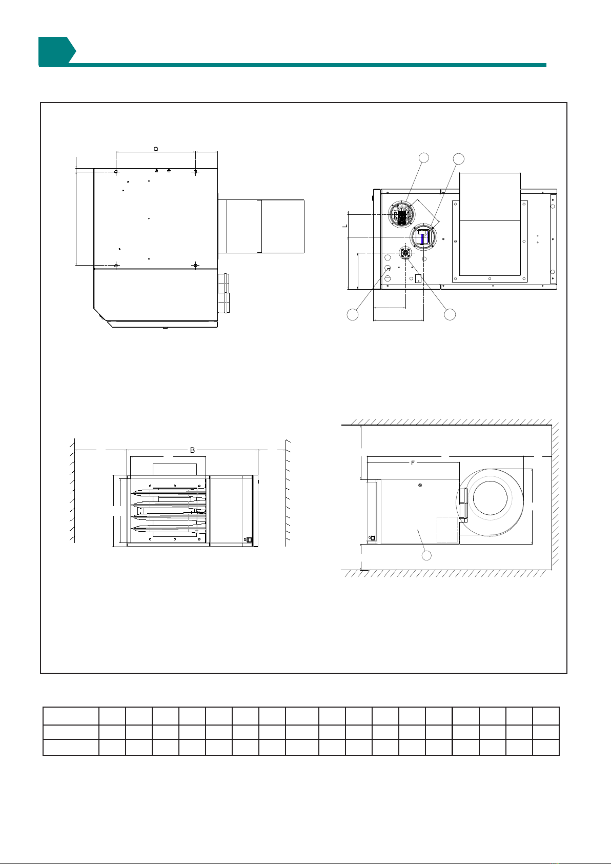
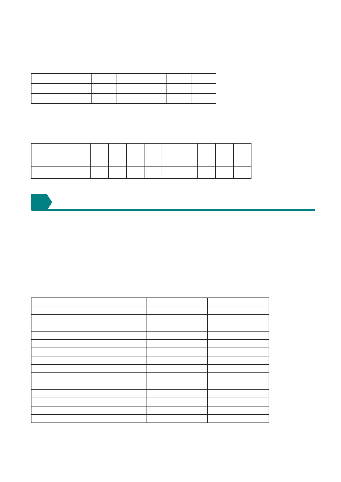
5. Dimensions 3
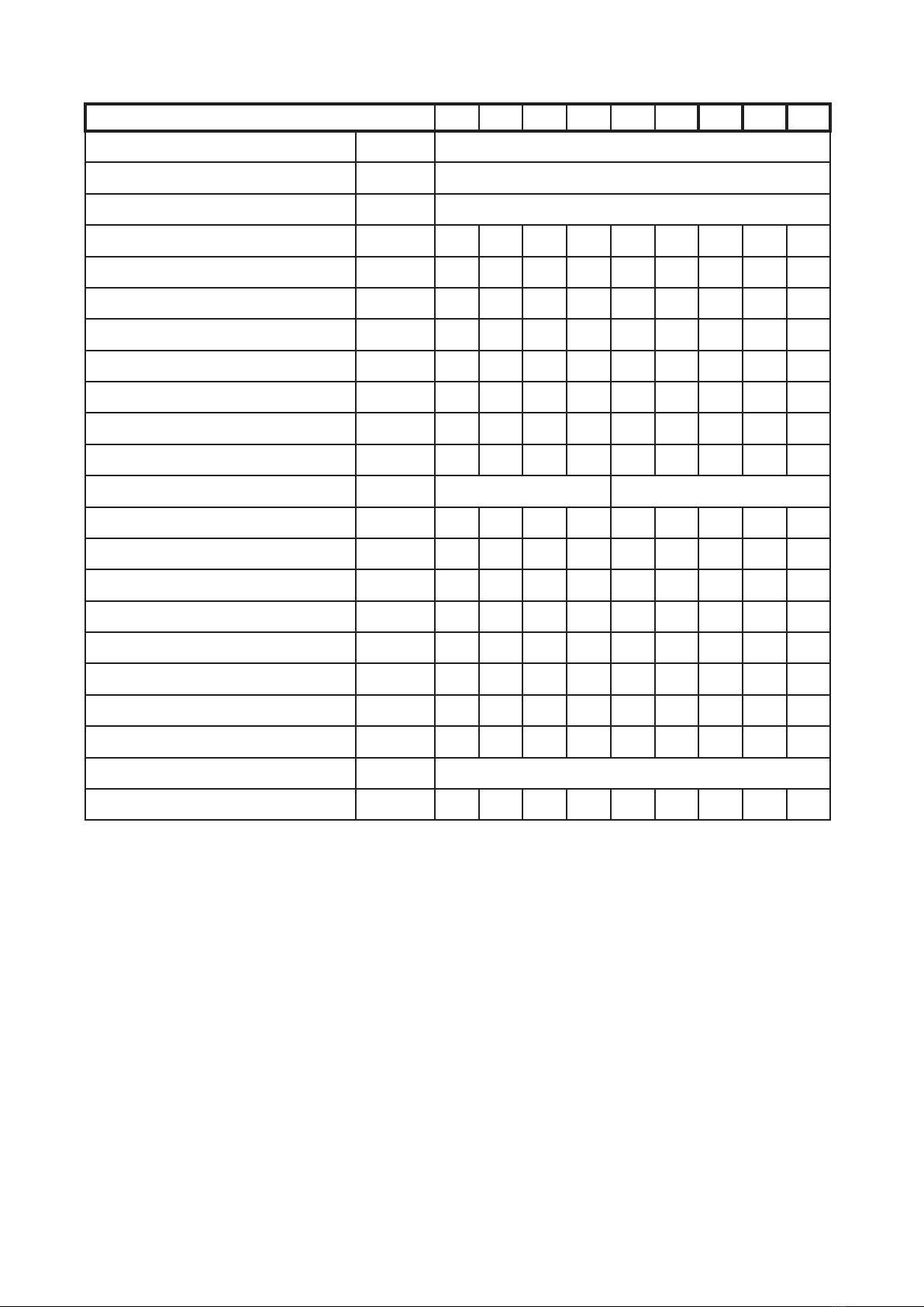
6. Technical data 6
7. Flueing requirements 10
8. Unit heater location 13
9. Hanging the unit 14
10. Gas piping and pressures 14
11. Electrical supply and connections 15
12. Check installation and start up 17
13. Maintenance schedule 20
14. Heat exchanger maintenance 21
15. Burner maintenance 22
16. Burner orice 23
17. Ignition system 23
18. Blower motor 24
19. Centrifugal fan 24
20. Gas valve 25
21. Combustion air pressure switch 26
22. Flue and combustion air system 26
23.Limit controls 26
24. Troubleshooting 27
25. Parts list 33
FOR YOUR SAFETY
What to do if you smell gas
• Do not try to light any appliance.
• Do not touch any electrical switch; do not use
any phone in your building.
• Immediately call your gas supplier.
• Evacuate all personnel.
• Do not store or use petrol or other ammable
vapours and liquids in the vicinity of this or any
other appliance.
WARNINGS
Improper installation, adjustment, alteration, service, or
maintenance can cause property damage, injury, or death.
Read the installation, operation, and maintenance instruc-
tions thoroughly before installing or servicing this equip-
ment.
Do not use this appliance if any part has been immersed
in water. Immediately call a qualied service technician to
inspect the appliance and replace any gas control that hes
been immersed in water.
Gas-red appliances are not designed for use in hazourdous
atmospheres containing ammable vapors or combustible
dust, in atmospheres containing chlorinated or halogenated
hydrocarbons or in applications with airborne silicone substances.
Should overheating occur, or the gas supply fail to shut off,
shut off the manual gas valve to the appliance before shutting
off the electrical supply.
This appliance is not intended for use by persons (including
children) with reduced sensory or mental capabilities or lack
of experience and knowledge, unless they have been given
supervision or instruction concerning use of the appliance
by a person responsible for their safety. Children should be
supervised to ensure that they do not play with the appliance.
These units must be installed in accordance with BS6230 or
BS5440 as appropriate plus all local building codes.
Models UDSBD-4E are design certied to the CE EN1020
standard for use in industrial and commercial installations
only. All models and sizes are available for use with either
natural or propane gas. The type of gas, the input rate and
the electrical supply requirement is shown on the heater rat-
ing plate. Check the rating plate to determine if the heater is
appropriate for the intended installation.
This installation manual is shipped with the heater. Verify that
the literature is correct for the heater being installed. If the
manual is incorrect for the heater, contact the supplier before
beginning installation.
The instructions in this manual apply only to the models listed.
Installation should be done by a suitably qualied installer in
accordance with these instructions. The installer is respon-
sible for the safe installation of the heater.
This unit was test operated and inspected at the factory prior
to crating and was in proper operating condition. If the heater
has incurred damage in shipment, document the damage with
the transport company and contact your supplier.
Check the rating plate for the gas and electrical specications
of the heater to be sure that they are compatible with the gas
and electric supplies at the installation site.
Read this booklet and become familiar with the installation
requirements of your heater. If you do not have knowledge of
local requirements, check with the gas supplier and any other
local agencies who might have requirements concerning this
installation.
Before beginning, make preparations for necessary supplies,
tools, and manpower. If the installation includes optional
vertical louvers or downturn nozzle etc., install these op-
tions before the heater is suspended. Follow the instruc-
tions included in the option package.
GENERAL
INSTALLATION CODES
UNCRATING/PREPARATION
Warranty is void if :
a. Wiring is not in accordance with the diagram furnished
with the heater.
b. The unit is installed without proper clearances as soon
as clearances are required regardless of the material be-
ing combustible.
c. A fan model is connected to a duct system or if the air
delivery system is modied.
WARRANTY