manuals.online logo
Brands
  1. Home
  2. •
  3. Brands
  4. •
  5. RF SOLUTIONS
  6. •
  7. Control System
  8. •
  9. RF SOLUTIONS ESPRIT LOW VOLTAGE Series User manual

RF SOLUTIONS ESPRIT LOW VOLTAGE Series User manual

ESPRIT L Remote control System
Quick Installaon Guide (systems only)
The ESPRIT system provides 4 switches each capable of switching up to 1KW (4A @ 110V). Each channel is inde-
pendent and separately controlled. The ESPRIT Remote control system provides 110V mains switched outputs via
each terminal.
1. First mount the ESPRIT system receiver box in the wall in your desired locaon.
2. Open the enclosure by removing xing screws from the enclosure front and then removing the front from the
enclosure.
3. Wire either MAINS, LIVE, Neutral and Earth connecons to the power supply screw terminal as shown below
(shown as A). Or wire 12-32Vac or 12-32Vdc to the low voltage terminals. (shown as B)
4. Wire your desired connecons to the relay switches (shown as C)
5. Once all required wiring is complete, use the handheld ESPRIT transmier to switch the outputs on and o.
6. As supplied, the handheld will operate the outputs - Buon 1 to output 1, Buon 2 to output 2 etc.
7. All buons will operate in a latching mode - Press for on, press again for o. It is possible to change the operaon
to momentary mode by ng the links (shown as D)
8. For advanced operaon such as adding extra transmiers dierent buon mapping opons see
datasheet.
Fig 1.1
Please contact RF Soluons if any components are missing
Sales: +44 (0) 1444 227910 Tech. Support: +44 (0) 1444 227909
RELAY 1 RELAY 3 RELAY 4
FUSE
POWER
TIMER
RELAY 1
RELAY 2
RELAY 3
RELAY 4
SYNC
TEST
ERASE
L N E
8
7
6
5
4
3
2
1
0Vdc
12-32Vdc
NO COM NC NO COM NC NO COM NC NO COM NC
CONNECT EITHER
110Vac OR 12-32Vdc
NEVER BOTH
110V INPUT
SUPPLY A
C
D
B
QS-ESPRIT-L-1
ESPRIT LOW VOLTAGE Series
Quick Start Guide
What’s in the box?
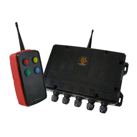
1 x Receiver with 5 addional
cable glands
1 x FOBBER Key Fob
(System only )
For full details of
ESPRIT’s
programmable
features, see
ESPRIT Remote
Control System
Quick Start Guide
Please contact RF Soluons if any components are missing.
Sales: +44 (0) 1444 227900 Tech Support: +44 (0) 1444 227909
ESPRIT L Remote control System
Receiver Guide
RELAY 1 RELAY 2 RELAY 3 RELAY 4
FUSE
POWER
TIMER
Timer Select Button –Used to select timer mode
Erase Button –Press and hold to erase all pairings, see
advanced operation for individual erase
Signal Test mode –press to enter signal test mode
Sync/Pair Button –Press once to auto pair. See
Advanced operation for other pairing options.
Momentary/Latching Jumper Links –It is possible to set the
relay switches on the ELITE receiver to either momentary or latching
operation.
Latching (link removed) - One press for on, one press for off.
Momentary (link fitted)- On while button is held only.
To set a relay switch to either momentary/latching choose the
associated link cap.
NOTE:
If link is changed, power cycle the
receiver (turn off/on) otherwise it will stay in the same mode it was
previously set in.
110Vac power
input
Power input fuse –should be 500mA
Relay switch terminals:
Common
Normally Open
Normally Closed
RELAY 1
RELAY 2
RELAY 3
RELAY 4
SYNC
TEST
ERASE
Status LEDs–Flash when
signals are sent/received
L N E
8
7
6
5
4
3
2
1
Mag sync –touch a
magnet to the plastic
case in the cross
hatched area to enter
sync mode without
opening the box.
0Vdc
12-32Vdc
NO COM NC NO COM NC NO COM NC NO COM NC
CONNECT EITHER
110Vac OR 12-32Vdc
NEVER BOTH
ESPRIT L Remote control System
Pairing a transmier
NOTE: The transmier supplied with the system should already be paired.
If an addional transmier needs to be paired, simply follow the below instrucons.
1. To SYNC a specic ESPRIT handheld transmier
buon to a specic output on the ESPRIT re-
ceiver box—press and release the SYNC buon on
the ESPRIT receiver board.
2. The ESPRIT receiver will ash all its relay output LED’s at a high rate to show that it is ready to
SYNC.
3. Press and release the SYNC buon again—the ESPRIT receiver will ash output LED1 this is
showing that output 1 is selected. Pressing and releasing the SYNC buon again will select
output 2 and so on, through to output 4.
4. Once you have selected the required output (only that out-
put LED is ashing) press and release the SPECIFIC buon
on the transmier that you wish to SYNC to the receiver.
5. The ashing LED’s will go out, the SYNC LED will ash quick-
ly for 2 seconds then go out.

Other RF SOLUTIONS Control System manuals

RF SOLUTIONS ELITE-RXL User manual

RF SOLUTIONS

RF SOLUTIONS ELITE-RXL User manual

RF SOLUTIONS PRO-CARLTON User manual

RF SOLUTIONS

RF SOLUTIONS PRO-CARLTON User manual

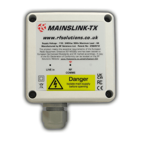
RF SOLUTIONS MAINSLINK User manual

RF SOLUTIONS

RF SOLUTIONS MAINSLINK User manual

RF SOLUTIONS Hornet-S2 User manual

RF SOLUTIONS

RF SOLUTIONS Hornet-S2 User manual

RF SOLUTIONS MAINSSWITCH-8SL1 User manual

RF SOLUTIONS

RF SOLUTIONS MAINSSWITCH-8SL1 User manual

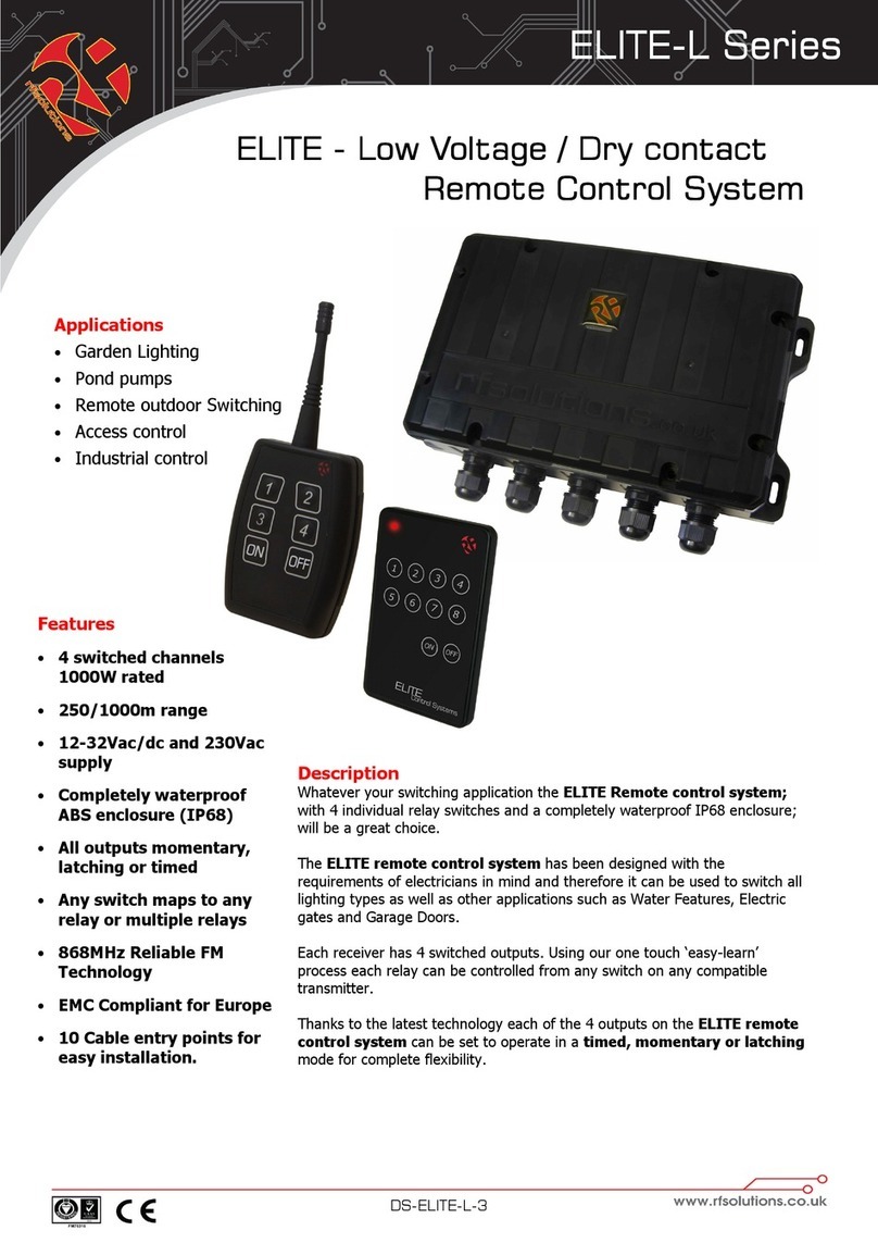
RF SOLUTIONS ELITE-L Series User manual

RF SOLUTIONS

RF SOLUTIONS ELITE-L Series User manual

RF SOLUTIONS HORNET200 User manual

RF SOLUTIONS

RF SOLUTIONS HORNET200 User manual

RF SOLUTIONS FOBLOQ Series User manual

RF SOLUTIONS

RF SOLUTIONS FOBLOQ Series User manual

RF SOLUTIONS MAINSSWITCH-8SL1 User manual

RF SOLUTIONS

RF SOLUTIONS MAINSSWITCH-8SL1 User manual

RF SOLUTIONS MAINSLINK-PRO User manual

RF SOLUTIONS

RF SOLUTIONS MAINSLINK-PRO User manual

Popular Control System manuals by other brands

Uponor Climate Control manual

Uponor

Uponor Climate Control manual

Avalon Instruments StarGo2 Pro user manual

Avalon Instruments

Avalon Instruments StarGo2 Pro user manual

PFU Limited SuperAdmin user guide

PFU Limited

PFU Limited SuperAdmin user guide

Intermatic PF1112T Installation, operation & service manual

Intermatic

Intermatic PF1112T Installation, operation & service manual

Toshiba TOSDIC-CIE DS Hardware operation manual

Toshiba

Toshiba TOSDIC-CIE DS Hardware operation manual

Woodway Micro-Link ZE0187 installation guide

Woodway

Woodway Micro-Link ZE0187 installation guide

Bryan Boilers CL Series brochure

Bryan Boilers

Bryan Boilers CL Series brochure

Dynatech SD-BOX Instructions for use and maintenance

Dynatech

Dynatech SD-BOX Instructions for use and maintenance

DoorKing 1620 Series installation manual

DoorKing

DoorKing 1620 Series installation manual

Rohde TC 504 instruction manual

Rohde

Rohde TC 504 instruction manual

Kolver ACE Screw Counter Operator's handbook

Kolver

Kolver ACE Screw Counter Operator's handbook

CommScope Teletilt ATC200-LITE-USB Setup

CommScope

CommScope Teletilt ATC200-LITE-USB Setup

ComfortNET CTK02AA installation guide

ComfortNET

ComfortNET CTK02AA installation guide

LOGICDATA LogicS Mounting instructions

LOGICDATA

LOGICDATA LogicS Mounting instructions

NICOR NLC Commissioning Guide

NICOR

NICOR NLC Commissioning Guide

SNAP PAC BRAINS SNAP-PAC-EB1 user guide

SNAP PAC BRAINS

SNAP PAC BRAINS SNAP-PAC-EB1 user guide

Fagor 8055 M Programming manual

Fagor

Fagor 8055 M Programming manual

Dormakaba BEST Wi-Q ONGUARD Interface User Guide

Dormakaba

Dormakaba BEST Wi-Q ONGUARD Interface User Guide

manuals.online logo
manuals.online logoBrands
  • About & Mission
  • Contact us
  • Privacy Policy
  • Terms and Conditions

Copyright 2025 Manuals.Online. All Rights Reserved.