Drive #0
I
V
Pressure
transmitter
Drive #0 Drive #1 Drive #2
I
V
I
V
I
V
Pressure
transmitter
1. JP4: Drive #0 àI position; Drive #1 ~ #3 àV position
2. JP1: Drive #0 àopen; Drive #1 ~ #3 àclose
3. DSW3: Drive #0 and Drive #3 àON position; Drive #1 and #2 à1 position
4. Set the number for every drive by F_016
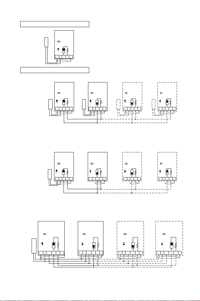
Single Pump Control(F_015=1)
2. Parallel control for four pumps with one pressure transmitter (special wiring)
1. Parallel control for four pumps with four pressure transmitters (standard wiring)
Drive #0 Drive #1 Drive #2
ON
I
V
I
V
I
V
Pressure
transmitter Pressure
transmitter Pressure
transmitter
1. JP4: Drive #0 àI position; Drive #1 ~ #3 àV position
2. JP1: Drive #0 àopen; Drive #1 ~ #3 àclose
3. DSW3: Drive #0 and Drive #3 àON position; Drive #1 and #2 à1 position
4. Set the number for every drive by F_016
3. Parallel control for four pumps with one pressure transmitter (special wiring)
1. JP4: Drive #0 ~ #3 àI position
2. JP1: Drive #0 ~ #3 àopen
3. DSW3: Drive #0 and Drive #3 àON position; Drive #1 and #2 à1 position
4. Set the number for every drive by F_016
Multi-Pump Control(F_015=2,3,4)
Drive #3
I
V
Pressure
transmitter
Drive #3
I
V
DSW3
JP4 JP4 JP4 JP4
JP4 JP4 JP4 JP4
JP4
ON
DSW3
1
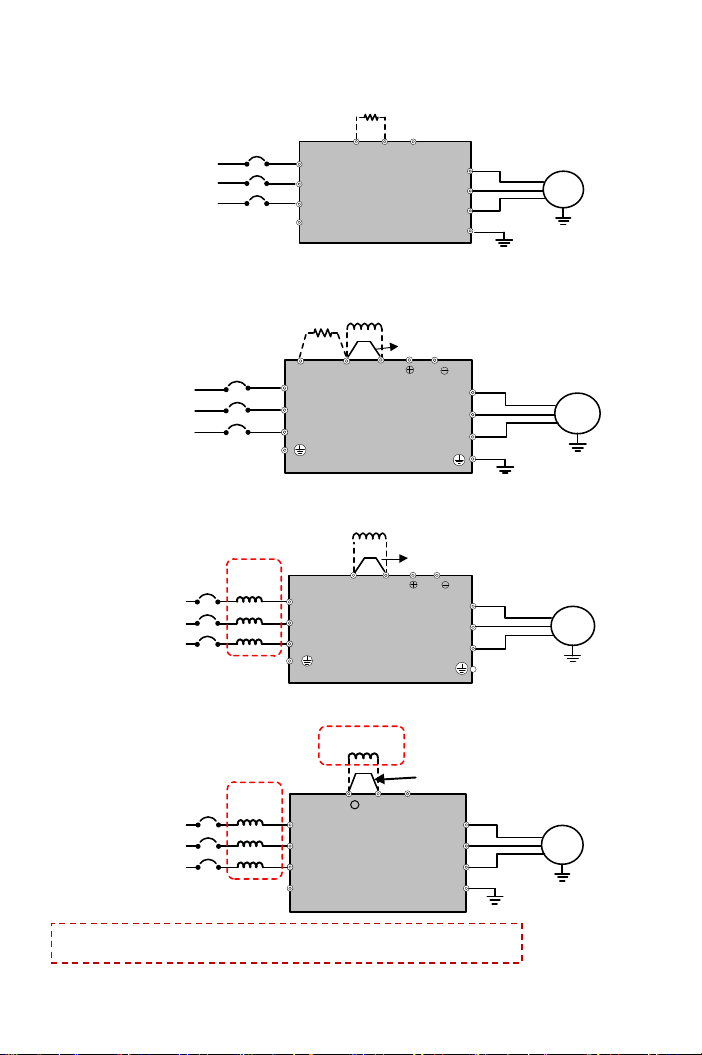
1. JP4: I position
2. JP1: Open
3. DSW3: ON position
4.F_015=1
JP4: Input signal type selection of Iin
JP1: Input impedance selection of Iin
DSW3: Terminal resistor switch
F_015: Selection of Pump Control Mode
F_016: Set Drive’s No for Parallel Control
1
ON
DSW3
1
ON
DSW3
1
ON
DSW3
1
ON
DSW3
1
ON
DSW3
1
ON
DSW3
1
P24 Iin DX+DX- FG
P24 Iin DX+ DX- FG
P24 Iin DX+ DX- FG P24 Iin DX+ DX- FG P24 Iin DX+ DX- FG
P24 Iin DX+DX- FG P24 Iin DX+DX- FG
ON
DSW3
1
P24 Iin DX+ DX- FG
P24 Iin DX+ DX- FG
JP1
JP1 JP1 JP1 JP1
JP1 JP1 JP1 JP1
–+
–+–+–+–+
–+
Drive #0
- +
Drive #1 Drive #2
ON
I
V
I
V
I
V
Pressure
transmitter
Drive #3
I
V
DSW3
JP4 JP4 JP4 JP4
1ON
DSW3
1ON
DSW3
1ON
DSW3
1
P24 Iin DX+DX- FG P24 Iin DX+ DX- FG P24 Iin DX+ DX- FG
P24 Iin DX+DX- FG
JP1 JP1 JP1 JP1
GND GND GND GND