manuals.online logo
Brands
  1. Home
  2. •
  3. Brands
  4. •
  5. Rice Lake
  6. •
  7. Control Unit
  8. •
  9. Rice Lake Load Ranger User manual

Rice Lake Load Ranger User manual

July 22, 2022 PN 214609 Rev A
www.ricelake.com
Content subject to change without notice.
© Rice Lake Weighing Systems 230 W. Coleman St. • Rice Lake, WI 54868
United States: 800-472-6703
International: +1 715-234-9171
Load Ranger 2.4 GHz RF Module Retrofit Quick Start Guide
This quick start guide contains condensed instructions of
installing 2.4 GHz RF module retrofit kits in the wheel weigh
pad and Ai-1 indicator.
For full instructions regarding retrofit and configuration, see
Load Ranger Technical Manual (PN 214194).
NOTE: Fully charge wheel weigh pad and Ai-1 indicator
before proceeding.
CAUTION: Wear grounding wrist strap when working
inside the Load Ranger to protect components from
electrostatic discharge (ESD).
1. Replace Radio Module in Wheel Weigh Pad
Figure 1. Retrofit Kit (212110)
1. Turn off wheel weigh pad and disconnect power cable.
2. Position wheel weigh pad with bottom facing up.
3. Remove two protection plate bolts, then remove plate
(Figure 2).
4. Remove six electronics cover mounting bolts, then open
electronics cover (Figure 2).
Figure 2. Protection Plate and Cover Mounting Bolts
5. Remove antenna, power cable and Bluetooth® module
cabling.
6. Remove Bluetooth® module mounting screw, then
Bluetooth® module.
Figure 3. Existing Hardware Removal
7. Remove jam nut and adhesive protector film from new
antenna, then slide black O-ring along cable and push
into adhesive.
8. Insert new antenna into cover while threading into
support plate.
9. Secure ground to support plate with M3 x 6 screw.
10. Remove CPU board Phillips mounting screw and O-ring
from CPU board mounting hole closest to support plate.
11. Secure ground to CPU board mounting hole with
previously removed Phillips screw and O-ring.
12. Secure ground to hole in antenna support plate with
Phillips screw.
Figure 4. Antenna and Ground Wire Installation
Item No. Description
1 2.4GHz Radio Frequency Module
2 Antenna (with O-ring)
3 Antenna Support plate
4 Ground wire
5 Phillips screw, M3 x 6 screw
6 Phillips screw, M3 x 9 self-tapping screw
2
3
5
4
1
6
Protection
Plate
Electronics
Cover
Antenna Bluetooth® Module
Power
Connectors
Antenna Cable
Communication
Cable
Mounting
Screw
Antenna Support Plate
Ground Wire
Mounting Screw and
O-ring
Ground Wire and
Support Plate
Mounting Screw
July 22, 2022 PN 214609 Rev A
www.ricelake.com
Content subject to change without notice.
© Rice Lake Weighing Systems 230 W. Coleman St. • Rice Lake, WI 54868
United States: 800-472-6703
International: +1 715-234-9171
13. Secure RF module (Bluetooth® module mounting
location) with Philips screw.
14. Connect communication cable to RF module and CPU
board COM2 TTL, antenna cable to RF module and
power cable to CPU board.
Figure 5. RF Module Installation
15. Repeat for remaining wheel weigh pads.
2. Replace Radio Module in Ai-1 Indicator
Figure 6. Ai-1 Indicator RF Retrofit Kit Parts (212111)
1. Turn off device and disconnect power cable.
2. Position Ai-1 indicator with bottom facing up.
3. Remove four cover mounting bolts, then remove cover.
Figure 7. Ai-1 Indicator Cover Mounting Bolts
4. Disconnect battery cabling and Bluetooth® radio cabling.
5. Remove existing antenna.
6. Remove Bluetooth® module mounting screw, then
Bluetooth® module.
Figure 8. Removing Bluetooth® Module
7. Remove jam nut and adhesive protector from antenna.
8. Insert antenna wire through antenna mounting hole on
front of cover then push antenna firmly in mounting hole.
9. Secure antenna with jam nut on inside of enclosure.
Figure 9. Install Antenna
10. Install new RF module in same location as Bluetooth®
module.
11. Connect communication cable to CPU board COM3 and
RF module J3, antenna cable to RF module and
reconnect battery cables.
Figure 10. Install RF Module
12. Reinstall rear cover and handles with four bolts.
Item No. Description
1 Phillips screw, 2.9 x 9.5 self-tapping screw
2 2.4GHz Radio Frequency Module
3 Antenna
COM 2 TTLAntenna WireMounting ScrewRF Module
3
1
2
Battery Cables
COM3
Antenna
Bluetooth® Module
Antenna Outside of
Enclosure
Jam Nut Inside of
Enclosure
RF Module
Communication Cable Antenna Wire
COM3
July 22, 2022 PN 214609 Rev A
www.ricelake.com
Content subject to change without notice.
© Rice Lake Weighing Systems 230 W. Coleman St. • Rice Lake, WI 54868
United States: 800-472-6703
International: +1 715-234-9171
3. Update Firmware
In order for wheel weigh pads and Ai-1 indicators originally
supplied with Bluetooth® modules to use RF modules, their
firmware must be updated.
IMPORTANT: Firmware update supports Windows 10
and 11 computers.
NOTE: Firmware update duration varies; plan for
approximately five to ten minutes for a wheel weigh pad
and 25 to 45 minutes for an Ai-1 Indicator.
1. Download 2.4GHz Load Ranger firmware from:
https://www.ricelake.com/firmware
2. Unzip firmware file (files for Ai-1 and indicator wheel
weigh pad are included):
NOTE: Firmware file names contain version numbers
and are equal to or greater than displayed above.
3. Attach a serial cable to the Ai-1 indicator’s serial port
and connect free end to computer.
NOTE: The Ai-1 indicator’s serial port is located on the
front panel.
Figure 11. Ai-1 Indicator Serial Port
4. Turn on Ai-1 indicator.
5. Run Ai-1 indicator firmware executable.
6. Select a serial port number from the drop-down menu.
7. Enable the USB->COM check box, if using a USB to
serial converter.
8. Select OK.
Figure 12. Firmware Update Configuration Window
9. A connection status indicator displays until a connection
between the computer and Ai-1 indicator is established.
Figure 1-1. Connection Status Window
10. Once communication is established, a firmware update
status window displays.
Figure 2. Firmware Update Status Window
11. When firmware has been updated, a success prompt
displays.
12. Select OK to close the window.
Figure 3. Firmware Success Prompt
13. After firmware update is completed, allow device to
reboot if it power cycles.
14. Power off Ai-1 indicator and remove serial cable.
15. Attach a serial cable to the wheel weigh pad’s serial port
and connect free end to computer.
NOTE: The wheel weigh pad’s serial port is located
inside the electronics cover on the CPU board.
Figure 4. Wheel Weigh Pad Serial Port
16. Run wheel weigh pad firmware executable.
17. Repeat steps Step 7 through Step 14.
18. Reinstall wheel weigh pad’s cover and protection plate
with previously removed hardware (Figure 2 on page 1).
19. Repeat steps Step 15 through Step 18 for remaining
wheel weigh pads.
Device Firmware File Name
Ai-1 Indicator EGT-AF13_07.07.00_XX_NL2.08_RICELAKE.exe
Weigh Pad
Dfw06WWSRF_05.03.00_ML_NL2.05_LCD_RICELAKE.exe
EXC-
SIG+
SIG-
EXC+
SIG-
SEN+
SEN-
SIG+
EXC-
EXC+
EXC-
SIG+
SIG-
EXC+
EXC-
SIG+
SIG-
EXC+
CELL2
CELL4CELL3
CELL1
J2
SENSE
+5V GND
COM 1
COM 1
B[-]
A[+]
GND
RX
CTS
TX
RS232/RS485
RS232
01 02
J4
ON
+5V
GND
J 1
CAL
RS232
COM 2
SENSOR BOOT
J3
CTS
RX
TX
+5V GND TX RX
COM2 TTL
COM 1
B[-]
A[+]
GND
RX
CTS
TX
RS232/RS485
July 22, 2022 PN 214609 Rev A
www.ricelake.com
Content subject to change without notice.
© Rice Lake Weighing Systems 230 W. Coleman St. • Rice Lake, WI 54868
United States: 800-472-6703
International: +1 715-234-9171
4. Default Wheel Weigh Pad
Wheel weigh pads must be defaulted after firmware update is
applied.
Figure 5. Wheel Weigh Pad Controls
1. Press to turn on the first wheel weigh pad.
2. Press during startup. TeCH flashes, then CAL
displays.
3. Press . AduanC displays.
4. Press . CaL.Par displays.
5. Press . DfLt.t displays.
6. Press .  displays.
7. Press to default the wheel weigh pad. 
displays while process runs, then CaL.Par displays.
8. Press two times to back out of the menu. 
displays.
9. Press .  briefly displays, then CaL displays.
See Load Ranger Technical Manual (PN 214194) to
recalibrate the wheel weigh pad.
10. Repeat for remaining wheel weigh pads.
5. Setup Wheel Weigh Pad
1. Press to turn on the first wheel weigh pad.
2. Press during startup. TeCH flashes, then CAL
displays.
3. Press repeatedly until SERiAL displays.
4. Press to enter the Serial menu. iD displays.
5. Press to enter the ID settings.
6. Press or to increase or decrease the selected
digit and press to move between the digits to enter
the pad ID number.
NOTE: The first Pad ID number must be 01 and the
remaining pad ID numbers must increment in ascending
numeric order. Example: 01, 02, 03. Do not configure
two pads with the same ID number.
Figure 6. Wheel Weigh Pad Positioning
7. Press . Con.rf displays.
8. Press until repeatedly radio displays.
9. Press . RF displays.
10. Press or until On displays.
11. Press . r.chan briefly displays.
12. Use arrows to enter a channel number.
NOTE: The default channel number is 27. The wheel
weigh pad channel number must match the Ai-1
indicator channel number it will pair with. The Ai-1
indicator supports channels 00 - 38. If using multiple
groups of Ai-1 indicators and wheel weigh pads, the
channel numbers must be unique for each group.
13. Press . OK briefly displays then Baud displays.
14. Press until wheel weigh pad resets.
15. Repeat for remaining wheel weigh pads.
MODE
SET
DIAG
NUM
SET
NUM
DATA
135
246
213
546
July 22, 2022 PN 214609 Rev A
www.ricelake.com
Content subject to change without notice.
© Rice Lake Weighing Systems 230 W. Coleman St. • Rice Lake, WI 54868
United States: 800-472-6703
International: +1 715-234-9171
6. Setup Ai-1 Indicator
1. Turn off all wheel weigh pads.
2. Press to turn on the Ai-1 indicator.
3. During startup, press the upper right corner of the
screen when the logo displays to enter the Technical
Setup menu.
Figure 7. Touch Upper Right Corner of the Display
4. Press to go to second Setup menu page.
5. In the second page, press
. Serial Port
menu displays.
6. Press .
Radio Frequency interface displays.
7. Press .
8. Enter the required channel number.
NOTE: The default channel number is 27. The wheel
weigh pad channel number must match the Ai-1
indicator channel number it will pair with. The Ai-1
indicator supports channels 00 - 38. If using multiple
groups of Ai-1 indicators and wheel pads, the channel
numbers must be unique for each group.
Figure 8. Channel Keyboard
9. Press . A Channel prompt displays.
Figure 9. Channel Success Prompt
10. Press to close the prompt and return to the
Radio Frequency interface menu.
11. Press twice.
12. Press once.
13. Press .
14. Press .
15. Press .
Number of Scales menu displays.
16. Select the number of wheel weigh pads to be used.
Figure 10. Number of Scales Configuration
17. Press .
18. Press .
19. Press .
Gravity value setting pop-up displays.
Serial ports
F2
Radio frequency interface
F5
Radio frequency interface
F5
Channel
F2
Channel
1Esc2
/
3
4 5
*
6
7BkSp8 -9
COK0
+
0 ~38
27
OK
Configuration sent Successfully.
Channel
OK
OK
Calibration
F1
Scale selection
F1
1 scale/s
Number of scales
F1
1
1
F1
2
F2
3
F3
4
F4
5
F5
6
F6
Number of scales 1/3
Cancel OK
OK
Gravity value setting
F4
1
July 22, 2022 PN 214609 Rev A
www.ricelake.com
Content subject to change without notice.
© Rice Lake Weighing Systems 230 W. Coleman St. • Rice Lake, WI 54868
United States: 800-472-6703
International: +1 715-234-9171
20. Enter the gravity value for the area the wheel weigh
pads will be used.
Figure 11. Set Gravity Value
21. Press to close the prompt and return to the
Calibration menu.
22. Press . Setup changed prompt displays.
Figure 12. Setup Changed
23. Press to save settings and complete setup.
Ai-1 indicator reboots to Weigh mode.
7. Pairing Ai-1 Indicator with Wheel Weigh Pads
1. Press to turn on the Ai-1 indicator.
2. Access the Technical Setup menu.
3. Turn on the first wheel weigh pad only (assigned ID 01)
and allow to connect.
4. Wheel weigh pad connects with Ai-1 indicator and
displays PL.1.
5. Repeat Step 1 and Step 4 for additional wheel weigh
pads.
6. Press .
7. If setup changed prompt displays. Press to
save settings.
Figure 13. Setup Changed
8. Ai-1 indicator reboots to Weigh mode.
Gravity value setting
1Esc2
/
3
4 5
*
6
7BkSp8 -9
COK0
+
9.75001 ~9.84999
9.8O39O
OK
Esc
Setup changed.
Save changes before restart the
indicator?
Technical setup
Cancel YesNo
Yes
Esc
Yes
Setup changed.
Save changes before restart the
indicator?
Technical setup
Cancel YesNo

Other Rice Lake Control Unit manuals

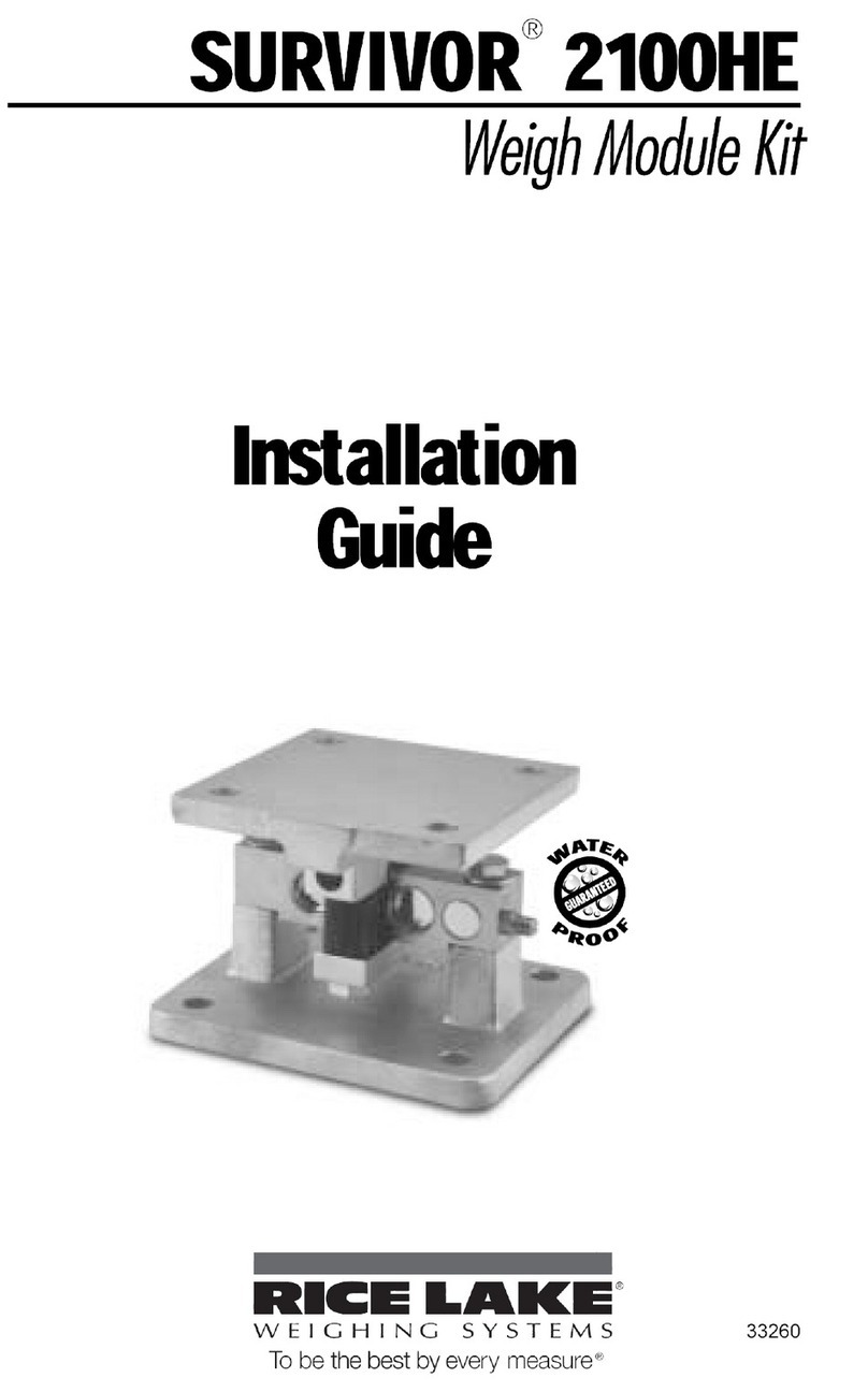
Rice Lake SURVIVOR 2100HE User manual

Rice Lake

Rice Lake SURVIVOR 2100HE User manual

Rice Lake LaserLight3 Manual

Rice Lake

Rice Lake LaserLight3 Manual

Rice Lake SCT-2200 User manual

Rice Lake

Rice Lake SCT-2200 User manual

Popular Control Unit manuals by other brands

Ammara Designs PBS-RGH installation instructions

Ammara Designs

Ammara Designs PBS-RGH installation instructions

Roger Technology AG CTRL Instruction and warnings for the installer

Roger Technology

Roger Technology AG CTRL Instruction and warnings for the installer

Sunsea AIoT SIMCom SIM5800 Hardware design

Sunsea AIoT

Sunsea AIoT SIMCom SIM5800 Hardware design

Madas M16/RMO N.A. manual

Madas

Madas M16/RMO N.A. manual

Spectron BM50 Series operating manual

Spectron

Spectron BM50 Series operating manual

Watts iDROSET CF Series installation manual

Watts

Watts iDROSET CF Series installation manual

ST Teseo-LIV4FM user manual

ST

ST Teseo-LIV4FM user manual

Keyvalve KP-28 operating & maintenance manual

Keyvalve

Keyvalve KP-28 operating & maintenance manual

Advantech Adam 4000 Series user manual

Advantech

Advantech Adam 4000 Series user manual

Emerson Fisher POSI-SEAL A31A instruction manual

Emerson

Emerson Fisher POSI-SEAL A31A instruction manual

Honeywell GSMVLP5-4G Installation and setup guide

Honeywell

Honeywell GSMVLP5-4G Installation and setup guide

Kessel Comfort Plus SD Instructions for installation, operation and maintenance

Kessel

Kessel Comfort Plus SD Instructions for installation, operation and maintenance

AVK 02 Series Installation and maintenance instructions

AVK

AVK 02 Series Installation and maintenance instructions

Samson 2405 Series Mounting and operating instruction

Samson

Samson 2405 Series Mounting and operating instruction

Leadshine Technology CS-D1008E user manual

Leadshine Technology

Leadshine Technology CS-D1008E user manual

Burkert 6650 operating instructions

Burkert

Burkert 6650 operating instructions

ProSoft Technology inRAx MVI56-HART user manual

ProSoft Technology

ProSoft Technology inRAx MVI56-HART user manual

Keysight M9362AD01 Startup guide

Keysight

Keysight M9362AD01 Startup guide

manuals.online logo
manuals.online logoBrands
  • About & Mission
  • Contact us
  • Privacy Policy
  • Terms and Conditions

Copyright 2025 Manuals.Online. All Rights Reserved.