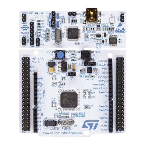
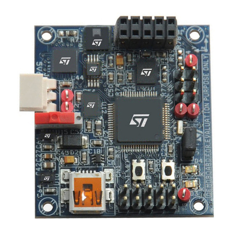
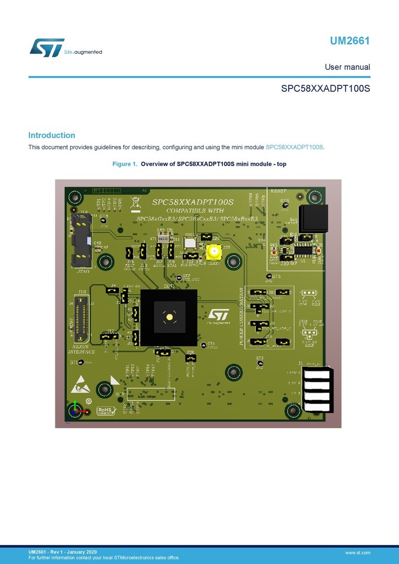
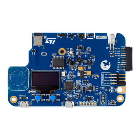
ST Teseo-LIV4FM User manual
Other ST Control Unit manuals

ST
ST Teseo-LIV3F User manual
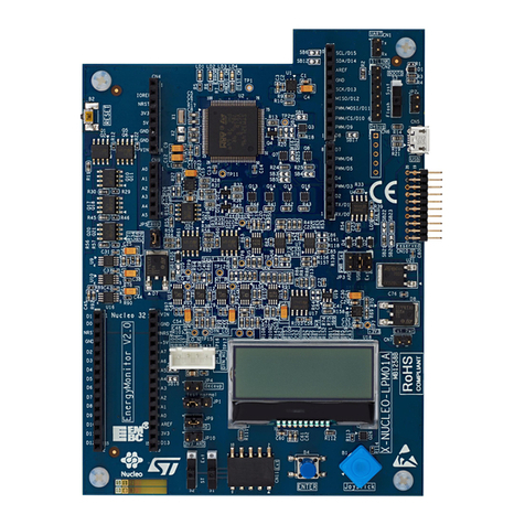
ST
ST X-NUCLEO-LPM01A User manual
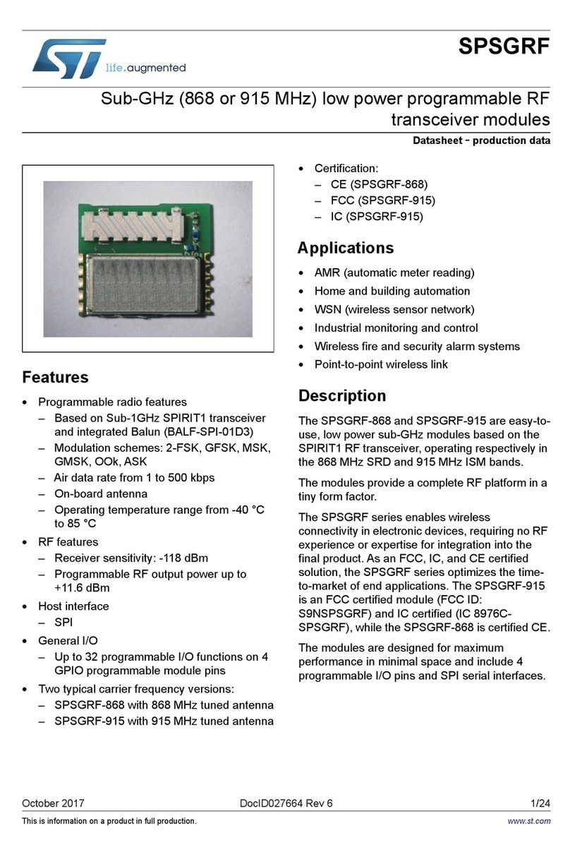
ST
ST SPSGRF User manual
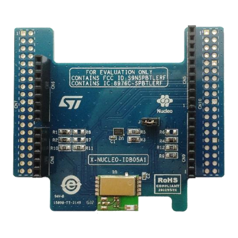
ST
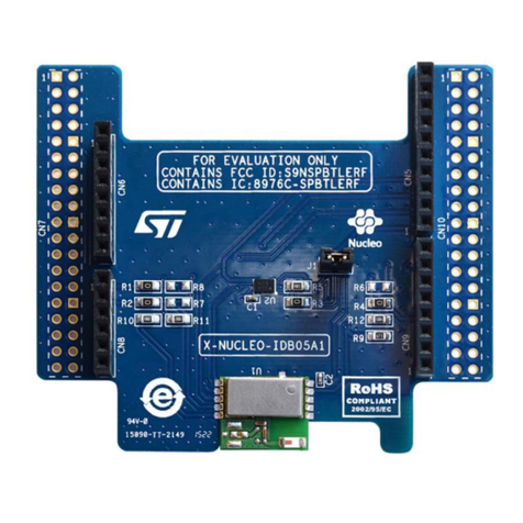
ST X-NUCLEO-IDB05A1 User manual
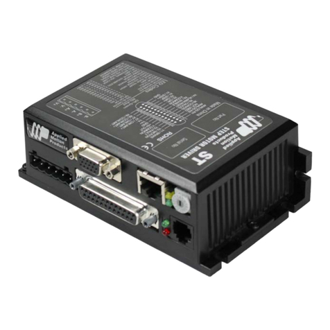
ST
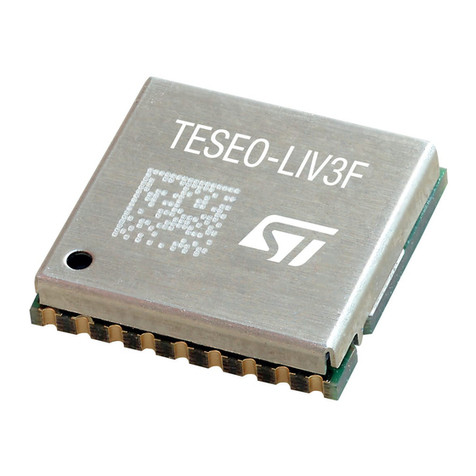
ST ST5-IP User manual
ST
ST Teseo-LIV3F User manual

ST
ST STM32Cube FP-SNS-MOTENVWB1 User manual
ST
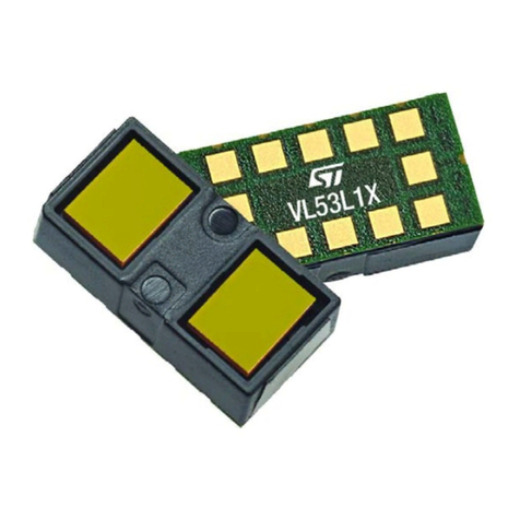
ST VL53L1X API User manual
ST
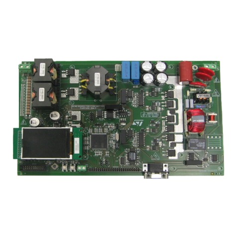
ST AN4070 Installation and operating instructions

ST
ST Teseo-LIV4F User manual
Popular Control Unit manuals by other brands

Festo
Festo Compact Performance CP-FB6-E Brief description

Elo TouchSystems
Elo TouchSystems DMS-SA19P-EXTME Quick installation guide

JS Automation
JS Automation MPC3034A user manual

JAUDT
JAUDT SW GII 6406 Series Translation of the original operating instructions

Spektrum
Spektrum Air Module System manual

BOC Edwards
BOC Edwards Q Series instruction manual

KHADAS
KHADAS BT Magic quick start

Etherma
Etherma eNEXHO-IL Assembly and operating instructions

PMFoundations
PMFoundations Attenuverter Assembly guide

GEA
GEA VARIVENT Operating instruction

Walther Systemtechnik
Walther Systemtechnik VMS-05 Assembly instructions

Altronix
Altronix LINQ8PD Installation and programming manual
