2
2.0 Mechanical Installation
2.1 General Installation Guidelines for Tank Mounts
1. Themountingsurfaceforthebaseandtopplatemustbelevel.Afterinstallation,
the top and bottom plates must be level within ±0.5°. If the mounting surfaces
are not level, then shims and/or grout may be used to level the mount.
Ifpossible,checkthatthemountislevelwhenthevesselisfullyloadedbecause
excessive deflections in legs and supporting structures may cause additional
sideforceswhichgreatlyaffectaccuracy.Deflectionofthemount’stoporbase
plate due to loading should not exceed ±.5°. Reinforcement of legs or other
support structures may be necessary to correct this. Vessels with long legs
should have cross bracing applied between adjacent legs to keep them from
spreading under load.
2. Compression mounting systems use three, four, or more mounts. More than
eight-module systems should be avoided as even weight distribution becomes
extremely difficult to achieve. The load on each mount assembly should vary
by no more than 20%. During installation, add shims where necessary to
achieve correct load distribution.
3. If the actual load cells are used during installation of the weighing assembly,
extreme care must be taken to prevent overload damage. A tank or hopper
weighingseveraltonscanexerthugeforces whendroppedonlyafractionofan
inch. Dummy load cells can be used during installation.
4. Itiscrucialthatallpipingorconduitbehorizontaland
flexible. If flexible piping is not used, make sure the
distancefromthe vesseltothe firstpipesupport is20-
30timesthe pipediameter.Fordetails, seethetechni-
cal information section of the RLWS Load Cell Prod-
uct Selection Guide. In smaller, lower capacity tanks
and hoppers, isolating the resultant forces becomes
extremely critical.
5. Load cells should not be installed in the mounts until all welding is completed.
The heat generated from welding current passing through a load cell can
damage the adhesive holding the strain gauge to the body. If possible, use a
dummy load cell when welding to maintain finished height. If welding is
unavoidable after load cell installation, connect the ground in such a way that
the current does not flow through the load cell. For example, if welding on the
mount top plate, the ground must be connected to the vessel, not to the mount
base or support structure. Also, protect the load cell and cable from weld
splatter.
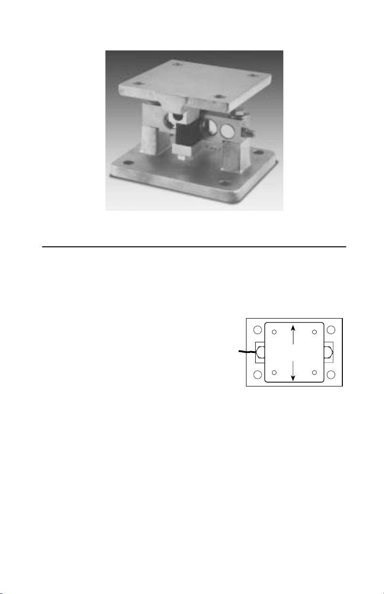
Note: The arrow on the load cell should point in the direction of the load.
6. All support points should be equally stiff so that they deflect by the same
amount as the vessel is loaded.
LEVEL±0.5°
FLEXIBLE PIPING
J-BOX