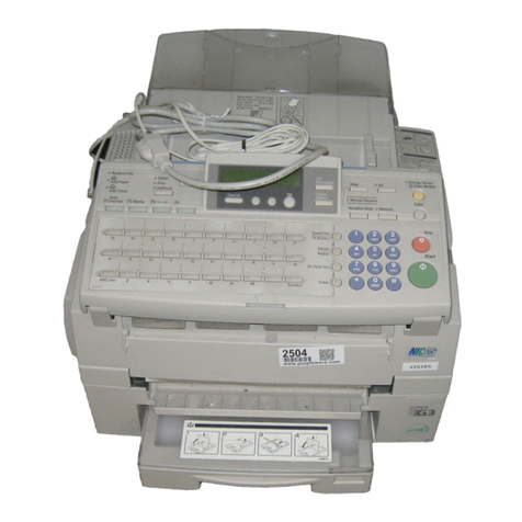
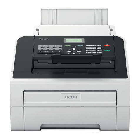
Ricoh fax180 User manual

BRO/BR1
RICOH FAX180/170
SERVICE MANUAL
August 7th, 1995
Subject to change

Lithium Batteries
ICAUTION
The danger of explosion exists if a battery of this type is incorrectly
replaced. Replace only with the same or an equivalent type
recommended by the manufacturer. Discard used batteries in
accordance with the manufacturer’s instructions.

1. OVERALL MACHINE INFORMATION
1.1. SPECIFICATIONS
Type
Desktop type transceiver
Circuit
PSTN, PABX
Connection
Direct couple
Document Size
Length:
105 - 357 mm [4.1 - 14.1 ins]
Up to 0.6 m [23.6 ins], manually assisted
Up to 14.0 m [46 ft], after adjustment
Width:
148 - 257 mm [5.8 - 10.1 ins]
Thickness:
0.05 to 0.15 mm [2 to 6 mils]
(equivalent 50 - 80 g/m2)
Document Feed
Automatic feed, face down
ADF Capacity
10 sheets (using 20 lb or 80 g/m2paper)
Scanning Method
Contact image sensor
Maximum Scan Width
A4 : 210 mm [8.3 ins] ± 0.5% B4
( CHINA ) : 256 mm [10.1 ins] ± 0.5%
Letter : 216 mm [8.5 ins] ± 0.5%
Scan Resolutions
Main scan: 8 dots/mm [203 dpi]
Sub scan:
Standard - 3.85 lines/mm [98 lpi]
Detail - 7.7 lines/mm [196 lpi]
Fine - 15.4 lines/mm [392 lpi]
Memory Capacity ( BRO only )
ECM: 64 kbytes
SAF:
BRO:(ECM on) 148 kbytes
(12 pages/Slerexe letter)
(ECM off) 204 kbytes
(16 pages/Slerexe letter)
China BRO:(TAM on) 256 kbytes
(21 pages/Slerexe letter)
(TAM off) 916 kbytes
(75 pages/Slerexe letter)
Compression
BR0: MH, MR, MMR, EFC, SSC
BR1: MH, MR, EFC, SSC
Protocol
Group 3
Modulation
V.29 (QAM), V.27ter (PHM), V.21 (FM)
Data Rate (bps)
9600/7200/4800/2400,
Automatic fallback
I/O Rate
With ECM: 0 ms/line
Without ECM: 10, 20, 40 ms/line
Transmission Time
BRO: 9 s at 9600 bps
BR1: 20 s at 9600 bps
Measured with G3 ECM using memory for a
ITU-T #1 test document (Slerexe letter) at
standard resolution
Printing System
Thermal Printing
Printer Roll; Thermal paper
North American version:
216 mm X 30 m [8.5 ins X 98.4 ft]
China version:
256 mm X 30 m [10.1 ins X 98.4 ft]
Other versions:
210 mm X 30 m [8.3 ins X 98.4 ft]
Maximum Printing Width
North American version: 210 mm [8.3 ins]
China version: 250 mm [9.8 ins]
Other versions: 204 mm [8.0 ins]
Print Resolutions
Main scan: 8 dots/mm [203 dpi]
Sub scan: 15.4 lines/mm [392 lpi]
Power Supply
USA : 115 ±20 Vac, 60 ±3 Hz
China : 220 ±20 Vac, 50 ±3 Hz
Asia : 220 - 240 V, 50/ 60 ±3 Hz
Operation Enviroment
Temperature: 17 ~ 28 °C [63 ~ 82 F]
Humidity : 40 ~ 70 %Rh
August 7th, 1995 OVERALL MACHINE INFORMATION
SPECIFICATIONS
1-1
Dimensions (W X D X H)
396 X 281 X 108 mm
[15.6" X 11.1" X 4.2"] excluding trays
Weight
Approx. 5 Kg [11 lbs] excluding trays and
thermal paper
OVERALL MACHINE INFORMATION August 7th, 1995
SPECIFICATIONS
1-2

1.2. FEATURES
KEY: O = Used, X = Not Used,
A= Chinese version only
Equipment BR0 BR1
ADF O O
Book scan X X
Built-in handset O O
Optional cassette: 100 sheets X X
Cabinet X X
Counter X X
Cutter O O
Hard disk X X
Marker (Stamp) X X
Monitor speaker O O
Optional printer interface X X
Video Processing Features BR0 BR1
Contrast O O
Halftone (Basic & Error Diffu-
sion) OO
MTF O O
Reduction X X
Resolution O O
Smoothing to 8 x 15.4 l/mm O O
Communication Features
- Auto BR0 BR1
Automatic fallback O O
Automatic redialing O O
Confidential reception X X
Dual Access O X
Substitute reception O X
Communication Features -
User Selectable BR0 BR1
Action as a transfer broad-
caster XX
AI Redial (last ten numbers) O X
Answering machine interface O O
Authorized Reception O O
Auto-answer delay time X X
Auto dialing (pulse or DTMF) O O
Auto Document O X
Auto image density selection O O
Auto paper size selection X X
Automatic Voice Message A X
Communication Features -
User Selectable BR0 BR1
Batch Transmission X X
Broadcasting O X
Chain Dialing O O
Communication Result Dis-
play XX
Confidential ID Override X X
Confidential Transmission X X
Direct Fax Number Entry O O
Economy Transmission X X
Fax on demand X X
Forwarding O X
Free Polling O O
Groups (3 groups) O X
Group Transfer Station X X
Hold X X
ID Transmission O O
Immediate Redialing O O
Immediate transmission O O
Keystroke Programs X X
Memory transmission O X
Multi-step Transfer X X
Next Transfer Station X X
OMR X X
On Hook Dial O O
Page Count O O
Personal Codes X X
Personal Codes with Conf. ID X X
Polling Reception O O
Polling Transmission O O
Polling tx file lifetime in the
SAF XX
Quick Dial (10 stations) O O
Reception modes (Fax, Tel,
Auto) OO
Length Reduction X X
Remote control features X X
Remote Transfer X X
Restricted Access X X
Secured Polling O O
Secured Polling with Stored
ID Override OO
Secure Transmission X X
Send Later O O
Silent Ringing Detection X X
Specified Image Area X X
Speed Dial 50 20
August 7th, 1995 OVERALL MACHINE INFORMATION
FEATURES
1-3

Communication Features -
User Selectable BR0 BR1
Super Fine Resolution
(16 x15.4 l/mm : 400 x 400
dpi) XX
Telephone Directory O O
Tonal Signal Transmission X X
Transfer Request X X
Transmission Deadline (TRD) X X
Turnaround Polling X X
Two-step Transfer X X
Two in one X X
Voice Request (immed. tx
only) XX
Communication Features -
Service Selectable BR0 BR1
AI Short Protocol O X
Auto-reduction Override Op-
tion OO
Busy tone detection O O
Closed Network (tx and rx) O O
Continuous Polling Reception X X
Dedicated tx parameters O O
ECM O X
EFC, SSC O O
Inch-mm conversion X X
Page retransmission times O O
Page separation mark X X
Protection against wrong
connection OO
Resol’n stepdown override
option XX
Short Preamble X X
Well log X X
Other User Features BR0 BR1
Area code prefix X X
Automatic service call X X
Center mark X X
Checkered mark X X
Clearing a memory file O X
Clearing a polling file O X
Clock O O
Confidential ID X X
Copy Editing (Erase Cen-
ter/Margin) XX
Copy mode O O
Other User Features BR0 BR1
Copy Mode Restriction X X
Counters O O
Daylight Saving Time O O
Destination Check X X
Direct entry of names O O
File Retention Time X X
File Retransmission X X
Function Programs X X
ID Code O O
Label Insertion X X
Language Selection O O
LCD contrast control X X
Memory Lock X X
Memory Lock ID X X
Modifying a memory file X X
Multi Sort Document Recep-
tion XX
Multicopy mode X X
Own telephone number O O
Power Saver (Night Timer
and standby mode) XX
Print density control X X
Printing a memory file O X
RDS on/off O O
Reception Mode Switching
Timer OO
Reception time printing X X
Reduction/Enlargement X X
Remaining memory indicator X X
Remote ID X X
Reverse Order Printing X X
RTI, TTI, CSI O O
Secure ID X X
Service Report Transmission O O
Speaker Volume Control O O
Substitute Reception on/off O X
Telephone Line Type O O
Paper Saving Mode O O
TTI on/off O O
User Function Keys X X
User Parameters O O
Wild Cards O O
Cutter on/off O O
Curled Paper Cut Off O O
OVERALL MACHINE INFORMATION August 7th, 1995
FEATURES
1-4

1.3. COMPONENT LAYOUT
1.3.1. Mechanical Components
No. Name Description
1ADF Roller Picks up pages of the document.
2R1 Roller Feeds the document through the scanner.
3CIS Spring This applies pressure against the scanner roller.
4
Contact Image Sensor
(CIS) Assembly This sensor reads and converts the light reflected from
the document into an analog video signal. An LED
array, which illuminates the document, is contained in
this unit.
5Scanner Roller Feeds the document through the scanner.
6Document Feed Roller Feeds the document through the scanner.
7Separation Pad Spring This applies pressure to prevent the ADF roller from
feeding more than one sheet at a time.
8Separation Pad Allows one page into the scanner.
9Decurler This applies stress to the paper to remove the curl.
10 Thermal Head This prints by applying heat to the thermal paper.
11 Platen Roller This feeds printouts out of the machine.
12 Thermal Head Spring This applies pressure against the platen roller.
13 Cutter Assembly This consists of the cutter sensor, paper guide frame,
rotary cutter blade, cutter motor, and printer jam sensor.
1
2
68
3
4
5
7910 11 12
13
H068D001.wmf
August 7th, 1995 OVERALL MACHINE INFORMATION
COMPONENT LAYOUT
1-5

1.3.2. Drive Components
No. Name Description
1Scanner Roller This feeds the document through the scanner.
2R1 Roller This feeds the document through the scanner.
3Scanner Roller Drive Gear This drives the scanner roller.
4R1 Roller Drive Gear This drives the R1 roller.
5Tx Motor This stepper motor drives the scanner.
6Scanner Drive Gear This drives the scanner roller.
7ADF Roller Drive Gear This drives the ADF roller.
8Rx Motor This stepper motor drives the platen roller.
9Platen Roller Drive Gear This drives the platen roller.
10 ADF Roller This picks up pages of the document and feeds them
into the scanner.
11 Platen Roller This feeds the paper out of the machine.
1
2
34567
8
9
10
11 H068D003.wmf
OVERALL MACHINE INFORMATION August 7th, 1995
COMPONENT LAYOUT
1-6

1.3.3. Electrical Components
1. PCBs
No. Name Description
1
Contact Image Sensor
(CIS) Assembly This sensor reads and converts the light reflected from
the document into an analog video signal. An LED
array, which illuminates the document, is contained in
this unit.
4OPU (Operation Panel
Unit) This board controls the operation panel.
9FCU (Facsimile Control
Unit) This board controls the machine. It contains the main
cpu, ROM, system RAM, drivers for the motors, a dc-dc
converter, and so on.
10 PSU (Power Supply Unit) This board supplies dc power to the machine.
14 NCU (Network Control
Unit) This board contains a relay and switches for interfacing
the machine to the network and the handset.
1
23
45
6
7
8
9
10
11
12
13
14
H068D002.wmf
August 7th, 1995 OVERALL MACHINE INFORMATION
COMPONENT LAYOUT
1-7

2. Motors
No. Name Description
6Tx Motor This stepper motor drives the scanner.
8Rx Motor This stepper motor drives the platen roller.
3. Sensors
No. Name Description
2Scan Line Sensor This detects when a page is approaching the scan line.
3Document Sensor This detects the presence of a document in the feeder.
5B4-width Sensor This detects when the width of the document is greater
than A4/LT size.
11 Printer Jam Sensor This detects when the paper is approaching the cutter,
and detects jams in the printer.
12 Cover Open/Paper End
Sensor This detects when the printer cover has been opened
and when the paper has run out.
13 Paper Size Detector This detects the paper size installed in the paper
holder. The user must install the correct size paper
guide.
4. Others
No. Name Description
7Monitor Speaker This allows the user to listen to the condition of the
telephone line.
OVERALL MACHINE INFORMATION August 7th, 1995
COMPONENT LAYOUT
1-8

1.4. OVERALL MACHINE CONTROL
The FCU (Facsimile Control Unit) contains the FCIP (Facsimile Control and
Image Processor), DRAM, SRAM, System ROM, and video processing mem-
ory, and controls the entire system.
The FCIP consists of the following component blocks:
•MDM - Modem•RU8 CPU - Main CPU •DIP - Digital Image Processor•LIF- Laser Interface •CKG - Clock Generator•RTC - Real Time Clock
•DCR - Data Compression and Reconstruction
The 256KB DRAM contains the SAF memory, ECM buffer memory, and work
area.
A 512 KB (4 Mbit) EPROM is used for the system ROM.
Note: The LIF (Laser Interface) is the same circuit used for laser fax
machines, adapted for use in thermal fax machines.
Contact
Image
Sensor
Amplifier
System
ROM
(4MEPROM)
System RAM
(SRAM)
DATA/ADDRESS BUS
Video
SRAM
Drivers
Thermal
Head
Thermistor
Tx
and
Rx motors
Operation
Panel
Sensors
Jam Sensor /
Paper End Sensor
Speaker
NCU
Handset
Control Signals
DRAM
Working
RAM ECM/SAF
Memory
FCIP
MDM CPU
RU8 DCR CKG DIP LIF
DC-DC
Converter
Amplifier
/ Filter
PSU
RTC
Cutter
FCU
H068D506.wmf
August 7th, 1995 OVERALL MACHINE INFORMATION
OVERALL MACHINE CONTROL
1-9

1.5. VIDEO DATA PATH
1.5.1. Transmission
Immediate Transmission:
Scanned data from the contact image sensor passes to the DIP block in the
FCIP. After analog/digital video processing, the DCR block compresses the
data for transmission. If ECM is switched on (BRO only), the compressed
data then passes to the ECM memory, before it is sent to the telephone line
through the modem. If ECM is switched off, or in the BR1 which has no
ECM, the data passes to the modem through a FIFO memory.
Memory Transmission (BRO only):
First, the scanned data is stored in the SAF memory after compression in the
DCR block.
At the time for transmission, the DCR block decompresses the data from the
SAF memory, then compresses it again after handshaking with the other ter-
minal is done. If ECM is switched on, the compressed data then passes to
the ECM memory, before it is sent to the telephone line through the modem.
FCU
To the network
Original
Amplifier
Video
Processing
Memory
DRAM
ECM/SAF
Memory
DATA/ADDRESS BUS
FCIP
DIP
DCR MDM
NCU
LED Array
Contact Image Sensor Assembly
Image Sensor
Amplifier
FIFO
Memory
DIP: Digital Image Processor
DCR: Data Compression & Reconstruction
MDM: Modem
H068V507.wmf
OVERALL MACHINE INFORMATION August 7th, 1995
VIDEO DATA PATH
1-10

1.5.2. Reception
Data from the line passes to the modem through the NCU. After the modem
demodulates the data, the decompressed data passes to the DCR block,
through the ECM memory, where the data is decompressed to raster image
data.
BRO only: At the same time, the compressed data passes to the SAF mem-
ory as a backup in case of mechanical problems during printing (substitute
reception.
The raster image data is then sent to the thermal head through the LIF block.
FCU
From the network
Copy Paper
Amplifier
DRAM
ECM/SAF
Memory
DATA/ADDRESS BUS
NCU
Thermal
Head
FCIP
MDM
DCR LIF
FIFO
Memory
LIF: Laser Interface
DCR: Data Compression & Reconstruction
MDM: Modem
H068V508.wmf
August 7th, 1995 OVERALL MACHINE INFORMATION
VIDEO DATA PATH
1-11

1.5.3. Copying
Single copy
The scanned data is sent to the thermal head through the LIF block, after
video processing in the DIP block.
FCU
Original
Amplifier
Video
Processing
Memory
DRAM
ECM/SAF
Memory
DATA/ADDRESS BUS
FCIP
DIP
DCR LIF
LED Array
Contact Image Sensor Assembly
Image Sensor
Copy Paper
Thermal
Head
FIFO
Memory
MDM: Modem
DCR: Data Compression & Reconstruction
LIF: Laser Interface
H068V509.wmf
OVERALL MACHINE INFORMATION August 7th, 1995
VIDEO DATA PATH
1-12

1.6. POWER DISTRIBUTION
1.6.1. Distribution Diagram
The PSU supplies +24V dc power to the FCU. The FCU converts the +24V
dc power supply to the following supplies.
+5V This is normally on when the main switch is on.
+5VBAT This supplies the system RAM on the FCU to back up the programmed data, if
the power is switched off. A lithium battery is used to generate +5VBAT.
+5VCIS This is a more stable power supply than +5V. It is used for the image sensor.
-5V This is used for the image sensor.
FCU
Thermal Head
Cutter
Scan Line
SN
PSU
AC/DC
Converter DC/DC Converter
Document
SN
B4 width
SN
JAM
SN
Rx Motor
Tx Motor
OP
Panel NCU CIS
Speaker
AC Power
+24V +5V
-5V
+5BAT
+5V +5V
+5VCIS
+5V
+24V
+5V
-5V
+24V
-5V
+5VCIS
+24V
+24V
+5V
+5V
+5V
+5V
+5V
+5V
Paper Size
SN
+24V
+5V
H068V501.wmf
August 7th, 1995 OVERALL MACHINE INFORMATION
POWER DISTRIBUTION
1-13

1.6.2. Memory Back-up
The +5VBAT supply from the lithium battery [A] backs up the system RAM
which contains system parameters and programmed telephone numbers,
and the real time clock in the main CPU.
BRO China model:
Two dry cells [B] and the dc/dc converter on the FCU back up the DRAM, if
there is data in the SAF memory and the power is switched off.
The dry cells generate about 3 volts (max. 3.2 volts). The dc/dc converter
(IC30) lifts this voltage to 5 volts so it can be used as the +5VD supply for
SAF backup. The CPU monitors the voltage of the +5VD supply with the
VDVDET signal. When the dry cells have run down, and the voltage is lower
than 4.4 volts, the CPU stops the dc/dc converter by dropping 1SAFFG to low
and the machine stops backing up the memory.
There is no battery switch for the battery [B].
FCU
FCIP
Switching
Circuit
System
RAM
DRAM
POWERS
5RTCCS
+5VBAT
+5V
VDVDET
1SAFFG
Q3
+5V
DC/DC
Converter
[IC30]
+5V
+5V
+5V
+5VBAT
[A]
[B]
H068V502.wmf
OVERALL MACHINE INFORMATION August 7th, 1995
POWER DISTRIBUTION
1-14

2. DETAILED SECTION DESCRIPTIONS
2.1. SCANNER
2.1.1. Mechanisms
1. Overview
The scanner consists of two mechanisms, a scanning mechanism and a
document feed mechanism.
The document feed mechanism consists of the ADF gear [A], ADF roller [B],
and separation rubber plate [C] to separate and feed the documents.
The scanning mechanism consists of the tx motor [D], the gear [E], R1 roller
driver gear [F], R1 roller [G], scanner roller drive gear [H], scanner roller [I],
and sensors [J]. The speed of the R1 and scanner rollers is kept constant.
The machine has no stamp in it.
[B] [A]
[D]
[E]
[F]
[G]
[H]
[I]
[J]
H068D013.wmf
[B]
[G]
[I] [C]
H068D004.wmf
August 7th, 1995 DETAILED SECTION DESCRIPTIONS
SCANNER
2-1
2. Document Detection
The document sensor [A] detects when a document is placed in the ADF.
The B4 width sensor [B] detects when the width of a document is over A4 or
LT. The scan line sensor [C] detects the leading edge of the document at the
scan line.
3. Prefeeding and Separation
The plate [A] aligns the leading edges of the pages of the document. When
the document sensor detects a document in the ADF, the machine starts pre-
feeding the document. The ADF roller [A] feeds the bottom sheet of the
document. Then, the R1 roller [C] feeds the sheet into the scanner.
The separation rubber plate [D] prevents the ADF roller from feeding more
than one sheet at a time.
[A]
[C]
H068D005.wmf
[C]
[B]
[A]
[D]
H068D007.wmf
[A]
[B]
[C]
H068D009.wmf
DETAILED SECTION DESCRIPTIONS August 7th, 1995
SCANNER
2-2

4. Drive Mechanism
The tx motor [A] drives the ADF roller [B], R1 roller [C], and scanner roller [D].
Because the scanner roller turns a bit faster than the R1 roller, the document
is always under tension.
The scanning speed for each resolution mode is as follows.
Resolution Scan speed (/A4)
Standard - Storage to SAF ( Memory Tx ) 12 s
Detail 23 s
Fine 46 s
The scanner can feed paper up to 257 mm (10.1") wide. However, the actual
scan width is 256 mm/B4 [10.1"] (China models), 210 mm/A4 [8.3"] (Asia
models) and 216 mm/Letter [8.5"] (USA models).
The maximum acceptable document page length can be adjusted to 0.6 m
(23.6"), 1.2 m (47.2"), or 14 m (46 ft). The default setting is 0.6 m.
Cross reference
Maximum document length: Scanner Switch 00, bits 2 and 3.
[A]
[B]
[C]
[D]
H068D003.wmf
August 7th, 1995 DETAILED SECTION DESCRIPTIONS
SCANNER
2-3

5. Image Scanning
The scanner consists of the scanner roller [A] and a contact image sensor
(CIS) assembly [B]. Inside the CIS are an exposure glass, a optical lens ar-
ray, an image sensor, and an LED array.
The image sensor consists of a row of 2048 photosensitive elements (256
mm width x 8 dots/mm). Light from the LED array is reflected from the docu-
ment and focused onto the image sensor by the optical lens array. Because
of the short optical path inside the CIS, the focal depth is much shorter than
for a CCD type scanner. The spring [C] pushes the CIS up, so that the docu-
ment always touches the exposure glass at the scan line.
The white level is stored in the SRAM on the FCU at the factory. The white
level must be adjusted when the ROM or CIS is replaced in the field, after
every time a RAM clear is done.
The image sensor scans the original one line at a time, and outputs an ana-
log signal for each line. The voltage from each element depends on the
intensity of the light reflected from the original onto the element; the intensity
of the light depends on the darkness of the area of the document it was re-
flected from.
Cross reference
White level adjustment: Service Table and Procedures (chapter 4), section 4.1.15
[A]
[B]
[C]
H068D004.wmf
DETAILED SECTION DESCRIPTIONS August 7th, 1995
SCANNER
2-4
This manual suits for next models
3
Table of contents
Other Ricoh Fax Machine manuals

Ricoh
Ricoh 1195L User manual

Ricoh
Ricoh 3800C Series User manual

Ricoh
Ricoh 1232 Series User manual

Ricoh
Ricoh Aficio 1018 User manual

Ricoh
Ricoh 170 / 180 User manual

Ricoh
Ricoh MV310 User manual

Ricoh
Ricoh Fax 680 MP User manual

Ricoh
Ricoh FAX1180L Installation instructions

Ricoh
Ricoh HL-F1 Quick start guide

Ricoh
Ricoh 2400L User manual

Ricoh
Ricoh FACSIMILE FAX77 Quick start guide

Ricoh
Ricoh SMFC210M SecureFax User manual

Ricoh
Ricoh FAX 1190L Safety guide

Ricoh
Ricoh 2000 User manual

Ricoh
Ricoh FAX4430L User manual

Ricoh
Ricoh fax1160l User manual

Ricoh
Ricoh 5510L User manual

Ricoh
Ricoh FAX1130L User manual

Ricoh
Ricoh FAX1400L User manual

Ricoh
Ricoh Stella-C1 Service manual