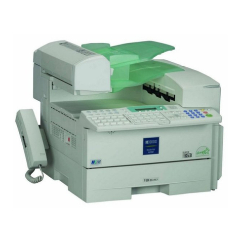
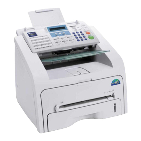
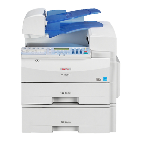
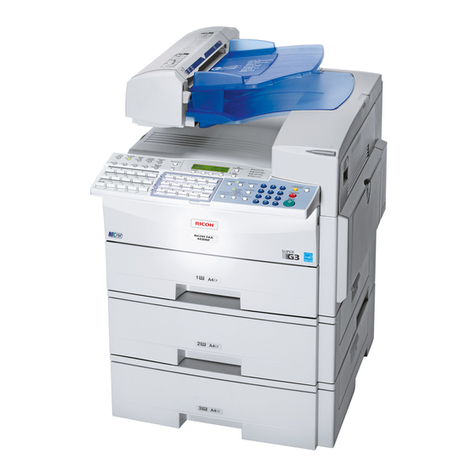
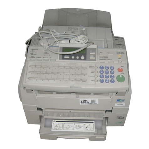
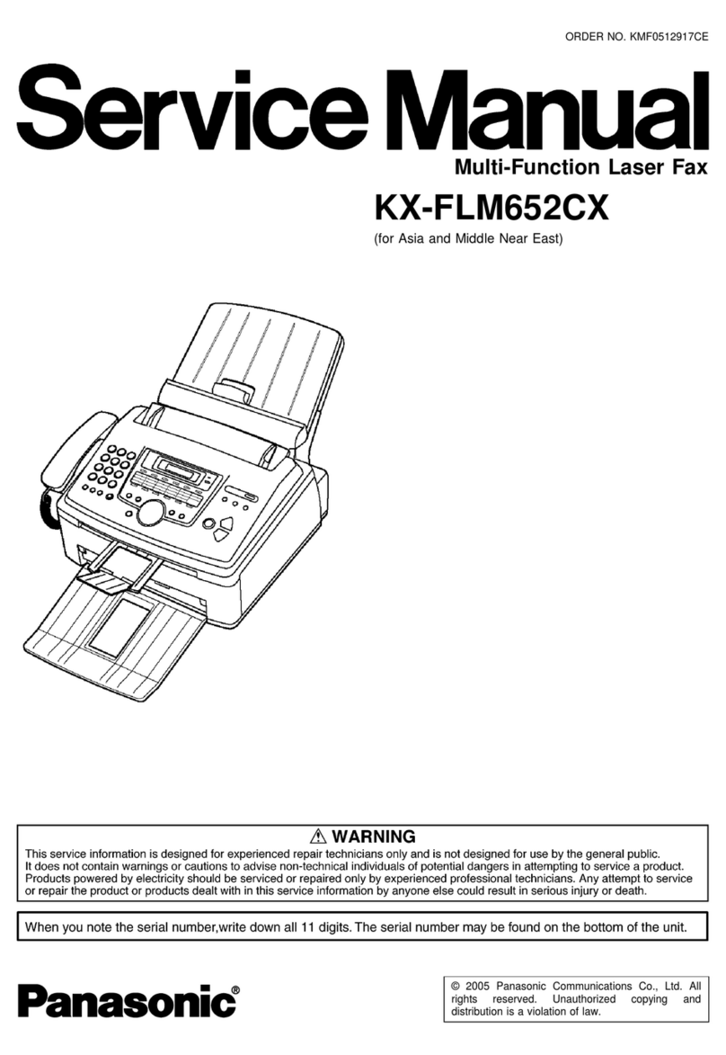
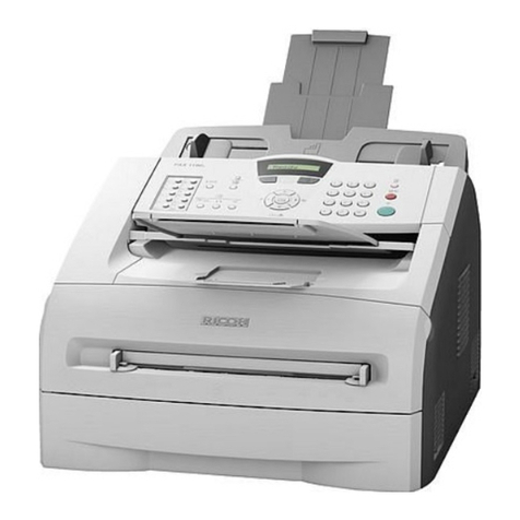
Ricoh 5510L User manual

MODEL K3
RICOH FAX 5510L
SERVICE MANUAL
14 June, 2002
Subject to change

!IMPORTANT SAFETY NOTICES
PREVENTION OF PHYSICAL INJURY
1. Before disassembling or assembling parts of the machine and peripherals,
make sure that the machine power cord is unplugged.
2. The wall outlet should be near the machine and easily accessible.
3. If any adjustment or operation check has to be made with exterior covers off
or open while the main switch is turned on, keep hands away from electrified
or mechanically driven components.
4. The inside and the metal parts of the fusing unit become extremely hot while
the printer is operating. Be careful to avoid touching those components with
your bare hands.
HEALTH SAFETY CONDITIONS
Toner is non-toxic, but if you get it in your eyes by accident, it may cause
temporary eye discomfort. Try to remove with eye drops or flush with water as
first aid. If unsuccessful, get medical attention.
OBSERVANCE OF ELECTRICAL SAFETY STANDARDS
1. Do not incinerate toner cartridge. Toner dust may ignite suddenly when
exposed to an open flame.
2. Dispose of used toner cassette in accordance with local regulations. (It is
non-toxic supply.)
3. Dispose of replaced parts in accordance with local regulations.
LITHIUM BATTERIES (MEMORY BACK-UP)
The danger of explosion exists if a battery of this type is incorrectly replaced.
Replace only with the same or an equivalent type recommended by the
manufacturer. Discard used batteries in accordance with the manufacture’s
instructions.
SAFE AND ECOLOGICAL DISPOSAL
1. Do not incinerate toner bottles or used toner. Toner dust may ignite suddenly
if exposed to an open flame.
2. Dispose of used toner, developer, and organic Photoconductor in
accordance with local regulations. (These are nontoxic supplies.)
3. Dispose of replaced parts in accordance with local regulations.

LASER SAFETY
The Center for Devices and Radiological Health (CDRH) prohibits the repair of
laser-based optical units in the field. The optical housing unit can only be repaired
in a factory or at a location with the requisite equipment. The laser subsystem is
replaceable in the field by a qualified Customer Engineer. The laser chassis is not
repairable in the field. Customer engineers are therefore directed to return all
chassis and laser subsystems to the factory or service depot when replacement of
the optical subsystem is required.
!WARNING
Use of controls not specified in this manual, or performance of
adjustments or procedures not specified in this manual, may result in
hazardous radiation exposure.
!WARNING FOR LASER UNIT
WARNING: Turn off the main switch before attempting any of the
procedures in the Laser Unit section. Laser beams can cause
serious damage to eyes.
CAUTION MARKING:
H310DECAL.WMF

i
TABLE OF CONTENTS
1. INSTALLATION...........................................................................1-1
1.1 MAINFRAME............................................................................................ 1-1
1.2 INSTALLING BASE UNIT/CABINET/SPACER......................................... 1-4
1.3 INSTALLING OPTIONAL UNITS.............................................................. 1-6
1.3.1 PAPER FEED UNIT TYPE 510........................................................ 1-6
1.3.2 BYPASS FEEDER TYPE 510.......................................................... 1-7
1.3.3 ISDN G4 INTERFACE UNIT TYPE 510........................................... 1-9
1.3.4 G3 INTERFACE UNIT TYPE510................................................... 1-12
1.3.5 FAX ON DEMAND TYPE 510........................................................ 1-15
1.3.6 FUNCTION UPGRADE UNIT TYPE 510....................................... 1-17
1.3.7 COUNTER TYPE 510.................................................................... 1-18
1.3.8 FEATURE EXPANDER TYPE 300 40M........................................ 1-19
2. PREVENTIVE MAINTENANCE...................................................2-1
2.1 SPECIAL TOOLS AND LUBRICANTS ............................................... 2-1
2.2 PM TABLE................................................................................................ 2-1
3. REPLACEMENT AND ADJUSTMENT........................................3-1
3.1 EXTERNAL COVERS............................................................................... 3-1
3.1.1 REMOVING THE ADF FRONT AND REAR COVERS.................... 3-1
3.1.2 REMOVING THE UPPER GUIDE PLATE ....................................... 3-1
3.1.3 REMOVING THE REAR COVER..................................................... 3-2
3.1.4 REMOVING THE OPERATION PANEL AND FRONT COVER....... 3-3
3.2 ADF/SCANNER SECTIONS..................................................................... 3-4
3.2.1 REPLACING THE PICK-UP ROLLER (PART OF THE ADF
MAINTENANCE KIT)....................................................................... 3-4
3.2.2 REPLACING THE FEED ROLLER (PART OF THE ADF
MAINTENANCE KIT)....................................................................... 3-4
3.2.3 REPLACING THE REVERSE ROLLER AND TORQUE LIMITER
(PART OF THE ADF MAINTENANCE KIT)..................................... 3-5
3.2.4 REPLACING THE R0 ROLLER....................................................... 3-6
3.2.5 REPLACING THE R1, R2 AND DOCUMENT EXIT ROLLERS....... 3-7
3.2.6 REPLACING THE CIS (CONTACT IMAGE SENSOR) (SCANNER)3-9
3.2.7 REMOVING THE STAMP UNIT..................................................... 3-10
3.2.8 ADJUSTING THE SCANNING TOP MARGIN............................... 3-10
3.3 LASER UNIT........................................................................................... 3-11
3.3.1 REPLACING THE LASER SYNCHRONIZATION DETECTOR AND
LD UNITS ...................................................................................... 3-11
3.3.2 REPLACING THE POLYGON MOTOR......................................... 3-12
3.3.3 ADJUSTING THE PRINTING SIDE-TO-SIDE REGISTRATION.... 3-13

ii
3.4 AIO CARTRIDGE ................................................................................... 3-14
3.4.1 REPLACING THE AIO CARTRIDGE............................................. 3-14
3.4.2 REPLACING THE TRANSFER ROLLER (PART OF THE FUSING
MAINTENANCE KIT)..................................................................... 3-15
3.4.3 REPLACING THE POWER PACK................................................. 3-16
3.5 PAPER FEED AND REGISTRATION..................................................... 3-17
3.5.1 REPLACING THE PAPER FEED ROLLER................................... 3-17
3.5.2 REPLACING THE REGISTRATION ROLLER............................... 3-18
3.5.3 ADJUSTING THE PRINTING TOP MARGIN................................. 3-19
3.6 SENSORS.............................................................................................. 3-20
3.6.1 REPLACING THE ADF/MDF SENSORS AND SWITCHES .......... 3-20
3.6.2 REPLACING THE PAPER-END LED BOARD AND PAPER SIZE
SENSOR SWITCH................................................................................... 3-22
3.6.3 REPLACING THE PAPER NEAR END SENSOR ......................... 3-23
3.6.4 REPLACING THE UPPER LIMIT AND PAPER END SENSORS.. 3-23
3.6.5 REPLACING THE AIO CARTRIDGE SENSOR............................. 3-24
3.6.6 REPLACING THE PAPER EXIT SENSOR.................................... 3-25
3.6.7 REPLACING THE TONER END SENSOR.................................... 3-26
3.6.8 REPLACING THE REGISTRATION SENSOR.............................. 3-27
3.7 FUSING UNIT......................................................................................... 3-28
3.7.1 REPLACING THE FUSING UNIT (PART OF THE FUSING
MAINTENANCE KIT)..................................................................... 3-28
3.7.2 DISASSEMBLING THE FUSING UNIT.......................................... 3-29
3.7.3 REPLACING THE PRESSURE ROLLER...................................... 3-30
3.7.4 REPLACING THE HOT ROLLER, FUSING LAMP, AND
THERMOFUSE.............................................................................. 3-31
3.7.5 REPLACING THE THERMISTOR ................................................. 3-32
3.7.6 REPLACING THE HOT ROLLER STRIPPERS............................. 3-33
3.8 PCBS...................................................................................................... 3-34
3.8.1 REPLACING THE PSU.................................................................. 3-34
3.8.2 REPLACING THE OPIF/NCU/FCU................................................ 3-35
1. OPIF board ...................................................................................... 3-35
2. FCU and MBU boards...................................................................... 3-36
3. NCU board....................................................................................... 3-37
3.8.3 REPLACING THE LCD CONTROLLER AND LCD BOARD.......... 3-38
3.8.4 REPLACING THE POWER PACK................................................. 3-39
3.8.5 REPLACING THE COOLING FAN ................................................ 3-40
3.9 BYPASS FEEDER UNIT......................................................................... 3-41
3.9.1 DISASSEMBLING THE BYPASS FEEDER UNITS....................... 3-41
3.9.2 REPLACING THE CLUTCH AND PAPER FEED ROLLER........... 3-42
3.9.3 REPLACING THE PAPER SIZE DETECTION SWITCH ............... 3-43
3.9.4 REPLACING THE CONNECTOR AND PAPER END SENSOR.... 3-44
3.10 DATA OR FIRMWARE DOWNLOAD/UPLOAD.................................... 3-45
3.10.1 DATA COPY BETWEEN THE IC CARD AND MACHINE............ 3-46
4. TROUBLESHOOTING.................................................................4-1
4.1 COPY QUALITY TROUBLESHOOTING.................................................. 4-1
4.1.1 BLANK COPIES............................................................................... 4-2
4.1.2 BLACK COPIES............................................................................... 4-2

iii
4.1.3 DIRTY BACKGROUND ................................................................... 4-3
4.1.4 UNEVEN IMAGE DENSITY............................................................. 4-4
4.1.5 VERTICAL BLACK LINES............................................................... 4-5
4.1.6 HORIZONTAL BLACK LINES.......................................................... 4-6
4.1.7 VERTICAL WHITE LINES................................................................ 4-7
4.1.8 HORIZONTAL WHITE LINES.......................................................... 4-8
4.1.9 BLACK DOTS/SPOTS..................................................................... 4-9
4.1.10 WHITE SPOTS IN BLACK IMAGE AREAS................................. 4-10
4.1.11 FAINT COPIES............................................................................ 4-11
4.1.12 VERTICAL BLACK BAND............................................................ 4-13
4.1.13 UNFUSED COPIES..................................................................... 4-13
4.1.14 GHOST IMAGE............................................................................ 4-14
4.1.15 TONER ON THE BACK OF THE PRINTER PAPER................... 4-14
4.1.16 INCORRECTLY ALIGNED OUTPUT (DATA SHIFTED TO THE
RIGHT OR LEFT)........................................................................ 4-15
4.1.17 INCORRECTLY ALIGNED OUTPUT (IMAGE SHIFTED
VERTICALLY)/REDUCED IMAGE .............................................. 4-15
4.2 MECHANICAL PROBLEMS ................................................................... 4-16
4.2.1 ADF/SCANNER............................................................................. 4-16
4.2.2 PRINTER....................................................................................... 4-18
4.3 SERVICE CALL CONDITIONS............................................................... 4-21
4.4 ERROR CODES..................................................................................... 4-22
4.5 MODEM STATUS CODES IN V.34 PROTOCOL DUMP........................ 4-32
4.5.1 CALLING SIDE.............................................................................. 4-32
Phase 1 (V.8)..................................................................................... 4-32
Phase 2 (Line Probing) ...................................................................... 4-32
Phase 3 (Equalizer Training).............................................................. 4-33
Phase 4 and 5 (Control Channel)....................................................... 4-33
Phase 6 (Primary Channel)................................................................ 4-33
Control Channel (Post Message - Sh)................................................ 4-34
Control Channel (Post Message - PPh)............................................. 4-34
Control Channel Recovery (AC)......................................................... 4-34
V.34 End............................................................................................ 4-35
4.5.2 CALLED SIDE................................................................................ 4-35
Phase 1 (V.8)..................................................................................... 4-35
Phase 2 (Line Probing) ...................................................................... 4-35
Phase 3 (Equalizer Training).............................................................. 4-36
Phase 4 and 5 (Control Channel)....................................................... 4-36
Phase 6 (Primary Channel)................................................................ 4-37
Control Channel (Post Message - Sh)................................................ 4-37
Control Channel (Post Message – PPh) ............................................ 4-38
Control Channel Recovery (AC)......................................................... 4-38
V.34 End............................................................................................ 4-38
4.6 ERROR CODES FOR THE ISDN OPTION............................................ 4-39
4.6.1 D-CHANNEL LAYER MANAGEMENT........................................... 4-40
4.6.2 D-CHANNEL, LAYER 1................................................................. 4-40
4.6.3 D-CHANNEL LINK LAYER............................................................ 4-40
4.6.4 D-CHANNEL NETWORK LAYER.................................................. 4-41
4.6.5 B-CHANNEL LINK LAYER............................................................. 4-41
i
v
4.6.6 B-CHANNEL NETWORK LAYER.................................................. 4-42
4.6.7 TRANSPORT LAYER.................................................................... 4-42
4.6.8 SESSION LAYER.......................................................................... 4-43
4.6.9 DOCUMENT LAYER ..................................................................... 4-44
4.6.10 PRESENTATION LAYER............................................................ 4-44
4.7 ISDN TEST FUNCTION.......................................................................... 4-45
4.7.1 LEDS ............................................................................................. 4-45
4.7.2 BACK-TO-BACK TEST................................................................... 4-46
5. SERVICE TABLES AND PROCEDURES ...................................5-1
5.1 SERVICE LEVEL FUNCTIONS................................................................ 5-1
5.1.1 BIT SWITCH PROGRAMMING (FUNCTION 01)............................. 5-1
5.1.2 SYSTEM PARAMETER LIST (FUNCTION 02)................................ 5-2
5.1.3 ERROR CODE DISPLAY (FUNCTION 03)...................................... 5-2
5.1.4 SERVICE MONITOR REPORT (FUNCTION 04)............................. 5-2
5.1.5 GROUP 3 PROTOCOL DUMP (FUNCTION 05) ............................. 5-2
5.1.6 RAM DISPLAY/REWRITE/MEMORY DUMP (FUNCTION 06)........ 5-3
5.1.7 COUNTER DISPLAY/REWRITE (FUNCTION 07)........................... 5-3
5.1.8 NCU PARAMETERS (FUNCTION 08)............................................. 5-4
5.1.9 MODEM TEST (FUNCTION 08)...................................................... 5-4
5.1.10 DTMF TONE TEST (FUNCTION 08)............................................. 5-5
5.1.11 V.8 MODEM TEST (FUNCTION 08).............................................. 5-5
5.1.12 V.34 MODEM TEST (FUNCTION 08)............................................ 5-6
5.1.13 OPERATION PANEL TEST (FUNCTION 09)................................ 5-6
5.1.14 LAMP TEST (B/W) (FUNCTION 10).............................................. 5-6
5.1.15 ADF TEST (FUNCTION 10)........................................................... 5-7
5.1.16 LAMP TUNING (FUNCTION 10).................................................... 5-7
5.1.17 LAMP TEST (COLOR) (FUNCTION 10)........................................ 5-8
5.1.18 PRINTER TEST PATTERNS (FUNCTION 11).............................. 5-8
5.1.19 PRINTER FREE RUN (FUNCTION 11)......................................... 5-8
5.1.20 RAM TEST (FUNCTION 12).......................................................... 5-9
5.1.21 DATA COPY (FUNCTION 12) ....................................................... 5-9
5.1.22 SERVICE STATION FAX NUMBER (FUNCTION 13) ................... 5-9
5.1.23 SERIAL NUMBER (FUNCTION 14)............................................. 5-10
5.1.24 40 MB FLASH MEMORY INITIALIZATION (FUNCTION 16)....... 5-10
5.1.25 40 MB FLASH MEMORY FORMATTING (FUNCTION 16).......... 5-11
5.1.26 40 MB FLASH MEMORY TEST (FUNCTION 16)........................ 5-11
5.1.27 G4 INTERNAL SWITCH PROGRAMMING (FUNCTION 17)....... 5-12
5.1.28 G4 PARAMETER SWITCH PROGRAMMING (FUNCTION 17).. 5-12
5.1.29 PRINTING G4 MEMORY DUMP (FUNCTION 17)....................... 5-13
5.1.30 PRINTING G4 PROTOCOL DUMP LIST (FUNCTION 17).......... 5-13
5.1.31 OPTIONAL G3 BIT SWITCHES (FUNCTION 18)........................ 5-14
5.1.32 OPTIONAL SG3 BOARD RAM DUMP (FUNCTION 18).............. 5-14
5.1.33 OPTIONAL SG3 BOARD NCU PARAMETERS (FUNCTION 18) 5-15
5.1.34 OPTIONAL SG3 BOARD MODEM TEST (FUNCTION 18)......... 5-15
5.1.35 OPTIONAL SG3 BOARD DTMF TONE TEST (FUNCTION 18).. 5-16
5.1.36 OPTIONAL SG3 BOARD V.8 MODEM TEST (FUNCTION 18)... 5-17
5.1.37 OPTIONAL SG3 BOARD V.34 MODEM TEST (FUNCTION 18). 5-17
5.1.38 LAN SW SETTING (FUNCTION 20)............................................ 5-18

v
5.1.39 LAN LINK CHECK (FUNCTION 20)............................................. 5-18
5.1.40 LAN LOOP BACK TEST (FUNCTION 20) ................................... 5-19
5.1.41 LAN LOG DUMP (FUNCTION 20)............................................... 5-19
5.1.42 LAN PING TEST (FUNCTION 20)............................................... 5-19
5.1.43 JPEG TEST (FUNCTION 21)....................................................... 5-20
5.1.44 IP-FAX IPG3 BIT SWITCHES (FUNCTION 22)........................... 5-20
5.1.45 IP-FAX PORT SETTING (FUNCTION 22)................................... 5-20
5.1.46 ROM VERSION (FUNCTION 23)................................................. 5-21
5.1.47 SENSOR INPUT (FUNCTION 24)............................................... 5-21
5.2 BIT SWITCHES...................................................................................... 5-24
5.2.1 SYSTEM SWITCHES.................................................................... 5-24
5.2.2 SCANNER SWITCHES ................................................................. 5-39
5.2.3 PRINTER SWITCHES................................................................... 5-40
5.2.4 COMMUNICATION SWITCHES.................................................... 5-43
5.2.5 G3 SWITCHES.............................................................................. 5-53
5.2.6 G3-2 SWITCHES........................................................................... 5-61
5.2.7 G4 INTERNAL SWITCHES............................................................ 5-67
5.2.8 G4 PARAMETER SWITCHES....................................................... 5-74
5.3 NCU PARAMETERS .............................................................................. 5-77
5.4 DEDICATED TRANSMISSION PARAMETERS..................................... 5-85
5.4.1 PROGRAMMING PROCEDURE................................................... 5-85
5.4.2 PARAMETERS.............................................................................. 5-86
5.5 SERVICE RAM ADDRESSES................................................................ 5-90
5.6 SERVICE RAM ADDRESSES: ADF AND SCANNER.......................... 5-110
5.7 SERVICE RAM ADDRESSES: PRINTER ENGINE (PLOTTER).......... 5-112
5.7.1 ADJUSTING THE PRINTING SIDE-TO-SIDE REGISTRATION.. 5-112
5.7.2 ADJUSTING THE PRINTING TOP MARGIN............................... 5-113
6. DETAILED SECTION DESCRIPTIONS.......................................6-1
6.1 ADF/SCANNER........................................................................................ 6-1
6.1.1 OVERVIEW...................................................................................... 6-1
6.1.2 DETAILED DESCRIPTIONS............................................................ 6-2
Document Detection............................................................................. 6-2
Document Pick-up................................................................................ 6-3
Document Feed.................................................................................... 6-4
Stamping.............................................................................................. 6-5
Returning to Ready Status................................................................... 6-6
Image Scanning................................................................................... 6-7
Jam Detection...................................................................................... 6-8
6.2 PRINTER.................................................................................................. 6-9
6.2.1 OVERVIEW...................................................................................... 6-9
6.2.2 LASER EXPOSURE ...................................................................... 6-10
Overview............................................................................................ 6-10
Optical Path........................................................................................ 6-10
Auto Power Control (APC)................................................................. 6-11
LD Safety........................................................................................... 6-12
LD Unit Service Call Condition........................................................... 6-12
6.2.3 AIO CARTRIDGE........................................................................... 6-13
Overview............................................................................................ 6-13

vi
Drive................................................................................................... 6-14
Drum Charge...................................................................................... 6-15
Development...................................................................................... 6-16
Drum Cleaning................................................................................... 6-18
Service Call Conditions for the Development Section........................ 6-18
6.2.4 TRANSFER AND PAPER SEPARATION...................................... 6-19
Overview............................................................................................ 6-19
Transfer Roller Cleaning .................................................................... 6-20
Service Call Conditions for the Transfer Section................................ 6-20
6.2.5 PAPER FEED................................................................................ 6-21
Overview............................................................................................ 6-21
Paper Size Detection ......................................................................... 6-23
Bottom Plate Lift, Upper Limit Detection and Paper End Detection.... 6-24
Paper Near-end Detection.................................................................. 6-25
Paper Feed ........................................................................................ 6-25
By-pass Tray...................................................................................... 6-26
6.2.6 FUSING ......................................................................................... 6-28
Overview............................................................................................ 6-28
Fusing................................................................................................ 6-30
Fusing Unit Drive................................................................................ 6-30
Fusing Pressure Roller, Separation, Exit ........................................... 6-31
Fusing Drive Release......................................................................... 6-31
Fusing Temperature Control .............................................................. 6-32
Cooling Fan Control........................................................................... 6-33
Fusing Unit Service Call Conditions................................................... 6-34
6.3 OPTIONAL PAPER FEED UNITS.......................................................... 6-35
6.3.1 OVERVIEW.................................................................................... 6-35
6.3.2 MECHANISMS............................................................................... 6-36
Paper Size Detection ......................................................................... 6-36
Bottom Plate Lift, Upper Limit Detection and Paper End Detection.... 6-37
Paper Near-end Detection.................................................................. 6-38
Paper Feed ........................................................................................ 6-39
Jam Detection.................................................................................... 6-39
6.4 PCBS...................................................................................................... 6-40
6.4.1 FCU ............................................................................................... 6-40
6.4.2 OPIF (OPTION INTERFACE BOARD) .......................................... 6-45
6.4.3 NCU............................................................................................... 6-46
6.4.4 PSU ............................................................................................... 6-46
6.4.5 NICF (NETWORK INTERFACE CARD FOR FACSIMILE)............ 6-47
6.4.6 SG3-D BOARD.............................................................................. 6-49
6.4.7 SIG4 BOARD................................................................................. 6-50
6.5 SYSTEM FEATURES............................................................................. 6-51
6.5.1 VERTICAL BLACK LINE CORRECTION....................................... 6-51
Overview............................................................................................ 6-51
Count Detection Parameters List ....................................................... 6-52
Settings for Vertical Black Line Detection .......................................... 6-53
Vertical Black Line Warning Message................................................ 6-53

vii
6.5.2 BLANK PAGE DETECTION........................................................... 6-54
Blank Page Detection Operation........................................................ 6-54
Blank Page Detection Switch Settings............................................... 6-54
6.5.3 ENERGY SAVER MODE............................................................... 6-55
Overview............................................................................................ 6-55
Setting the Energy Saver Mode Timer............................................... 6-56
How the Energy Saver Mode Operates.............................................. 6-57
Important Points About Energy Saver and Standby........................... 6-60
6.5.4 ERASE ALL REGISTERED SETTINGS........................................ 6-61
6.5.5 RECEIVING FROM A FAX INFORMATION SERVICE.................. 6-62
6.5.6 DUAL ACCESS.............................................................................. 6-63
Dual Access Jobs and Resources...................................................... 6-63
Additional Dual Access Limitations .................................................... 6-64
Simultaneous Broadcasting................................................................ 6-65
6.5.7 OPERATION LOG......................................................................... 6-66
Memory Dump List............................................................................. 6-66
6.5.8 SENDING COLOR DOCUMENTS................................................. 6-68
6.5.9 SCAN RESOLUTION..................................................................... 6-69
SPECIFICATIONS.................................................................... SPEC-1
1.1 SPECIFICATIONS.......................................................................SPEC-1
1.2 FEATURES..................................................................................SPEC-3
1.2.1 FEATURES LIST......................................................................SPEC-3
1.2.2 CAPABILITIES OF PROGRAMMABLE ITEMS ........................SPEC-6
1.3 COMPONENT LAYOUT ..............................................................SPEC-7
1.3.1 MECHANICAL COMPONENTS................................................SPEC-7
1.3.2 ELECTRICAL COMPONENTS.................................................SPEC-8
PCBs.............................................................................................SPEC-9
Motors.........................................................................................SPEC-10
Sensors.......................................................................................SPEC-10
Interlock Switch...........................................................................SPEC-11
Others.........................................................................................SPEC-11
1.3.3 DRIVE LAYOUT......................................................................SPEC-12
Components................................................................................SPEC-12
1.4 POWER DISTRIBUTION...........................................................SPEC-13
1.4.1 DISTRIBUTION DIAGRAM.....................................................SPEC-13
1.4.2 MEMORY BACK-UP CIRCUIT................................................SPEC-14

14 June, 2002 MAINFRAME
1-1
Installation
1. INSTALLATION
!CAUTION
Do the following before installing an optional unit:
1. Print out all messages stored in the memory.
2. Print out the lists of user-programmed items and the system parameter list.
3. Turn off the main switch, and disconnect the power plug.
1.1 MAINFRAME
1. Remove the mainframe from the box.
2. Remove the shipping tape.
H310I939.WMF
H310I001.WMF

MAINFRAME 14 June, 2002
1-2
3. Remove the shock absorber [A] and sheet
[B].
4. Remove the shock absorbers and
shipping tape from the paper trays.
5. Attach the document exit tray and
document tray.
6. Open the ADF unit and attach the handset
bracket [C].
7. Open the left cover and remove the AIO cartridge.
8. Shake the AIO cartridge left to right then
back and forth about 7-8 times (total).
Then, remove the toner ribbon seal.
9. Reinstall the AIO cartridge.
10. Load the desired paper in the paper trays,
and set up the paper size dials
accordingly
11. Turn the machine ON, then follow the
display to program the following items:
Date/time, PSTN line type (tone/pulse
dial), own name, fax header, fax number.
12. Program the machine serial number in
Service mode, then exit Service mode.
H310I002.WMF
H310I940.WMF
H310I991.WMF
[A]
[B]
[C]

14 June, 2002 MAINFRAME
1-3
Installation
13. Remove the backing from the brand
plaque [A] and avoid touching the
adhesive surface. Place the brand
plaque in the depression on the ADF
front cover. Taking care that the brand
plaque is orientated correctly and
aligned straight. Once in place, apply
even pressure beginning at the center
of the brand plaque moving toward the
outer edges. This will insure that it is
well adhered to the surface.
H310I059.WMF
[A]

INSTALLING BASE UNIT/CABINET/SPACER 14 June, 2002
1-4
1.2 INSTALLING BASE UNIT/CABINET/SPACER
To ensure proper machine stability, be sure to attach the Cabinet Type 510 when
installing 2 PFUs/Spacer Type 510, or the Base Unit Type 510 when installing 3 or
more PFUs/Spacer Type 510 (both of which have Support Boards attached).
Please refer to the following examples:
Example 1: Mainframe, PFU X 2 and Cabinet Type 510
Example 2: Mainframe, Spacer Type 510 X 2 and Cabinet Type 510
H310I056.WMF
H310I057.WMF
Cabinet Type 510
M4 screws
Support Board
Cabinet Type 510
Support Board
M3 screws
M4 screws
Spacer Type 510

14 June, 2002 INSTALLING BASE UNIT/CABINET/SPACER
1-5
Installation
Example 3: Mainframe, PFU X 4 and Base Unit Type 510
NOTE: As shown in the illustrations above, when attaching any of the units directly
under the mainframe, use the two forward parallel screw-holes. For all
other attachments, use the two diagonally positioned screw holes.
H310I058.WMF
Base Unit Type 510
Support Board
M3 screws

INSTALLING OPTIONAL UNITS 14 June, 2002
1-6
1.3 INSTALLING OPTIONAL UNITS
1.3.1 PAPER FEED UNIT TYPE 510
1. When installing optional Paper Feed Units 2,
3 or 4 (i.e. ones not attached directly under
the mainframe), it is necessary to replace the
large leg [A] with the small leg [B] enclosed
with the unit.
NOTE: Remove the 2 tie-wraps securing the
paper feed rollers (located under the
red tag).
2. Place the mainframe and any attached PFUs
on top of the Paper Feed Unit [C], then
secure the two with the bracket [D] (1 screw)
on the front of the machine
NOTE: If the existing mainframe and PFU
assembly is too heavy, disassemble
them and install them one by one on
top of the new optional PFU.
3. Remove the connector cover [E] (1 screw)
and secure the new PFU to the mainframe
(or PFU) above it with the bracket [F] (2 screws).
Then, connect the harness [G] to the machine
and reattach the connector cover.
4. Plug in the machine and turn on the main power
switch.
5. Print the System Parameter List from inside
Service mode, then make sure that
“CASSETTE” is listed as an option. Then exit
Service mode.
6. Add some paper and make some test prints
using the newly installed PFU.
H206I601.WMF
H206I602.WMF
H206I603.WMF
[B]
[A]
[C]
[D]
[E]
[F]
[G]

14 June, 2002 INSTALLING OPTIONAL UNITS
1-7
Installation
1.3.2 BYPASS FEEDER TYPE 510
1. Remove the rear cover [A] (7 screws) and
small cut-out [B] as shown.
2. Open the large cover. Then, remove the 2
screws [C] as shown to release the small
cover.
3. Attach the 2 magnet catches [D], 2 small
brackets [E] and 2 cushions [F]. Then attach
the knob [G] (2 screws) to the small cover as
shown.
H207I029.WMF
H207I030.WMF
H207I031.WMF
[A]
[B]
[C]
[G]
[F]
[E]
[D]

INSTALLING OPTIONAL UNITS 14 June, 2002
1-8
4. Attach the gear assembly [H] to the
back of the machine. Then, attach the
connector [I] and lead the bypass
feeder harness through the 3 clamps
as shown. Finally, connect the end of
the harness [J] and secure the
grounding wire [K] to the mainframe.
5. Reattach the rear cover.
6. Attach the bypass feeder [L] to the
machine.
7. Plug in the machine and turn on the main power switch.
8. Print the System Parameter List from inside Service mode, then make sure that
“BY-PASS” is listed as an option. Then, exit Service mode.
9. Add some paper and make some test prints using the newly installed Bypass
Feeder.
H207I032.WMF
H207I033.WMF
[H]
[I]
[J]
[K]
[L]

14 June, 2002 INSTALLING OPTIONAL UNITS
1-9
Installation
1.3.3 ISDN G4 INTERFACE UNIT TYPE 510
1. Remove the upper cover [A] (2 screws).
2. Remove the rear cover (7 screws) [B] and cut
away the ISDN small cover as shown.
3. Remove the bracket cover [C] (4 screws) as shown.
H208I006.WMF
H208I013.WMF
H208I523.WMF
[C]
[B]
[A]

INSTALLING OPTIONAL UNITS 14 June, 2002
1-10
4. Connect the harness [D] to the SiG4 board
[E] and insert the board into the SiG4
connector on the OPIF board [F].
5. Reattach the bracket cover [C], then lead
the harness [D] through the 3 clamps and
the hole [G] in the rear bracket as shown.
6. Remove the bracket assembly [H] from
rear side of the machine as shown.
H208I019.WMF
H208I020.WMF
H208I040.WMF
[D]
[F]
[D]
[H]
[E]
[C]
[G]
This manual suits for next models
1
Table of contents
Other Ricoh Fax Machine manuals

Ricoh
Ricoh 3900L User manual

Ricoh
Ricoh 1000L Quick start guide

Ricoh
Ricoh LASER FACSIMILE User manual

Ricoh
Ricoh FAX1180L Installation instructions

Ricoh
Ricoh FT5233 User manual

Ricoh
Ricoh FAX 1190L User manual

Ricoh
Ricoh B383 User manual

Ricoh
Ricoh FAX4500L User manual

Ricoh
Ricoh 1195L User manual

Ricoh
Ricoh MV74 User manual

Ricoh
Ricoh fax180 User manual

Ricoh
Ricoh F102 User manual

Ricoh
Ricoh fax1900L User manual

Ricoh
Ricoh FAX 1190L User manual

Ricoh
Ricoh 1190L Operating and safety instructions

Ricoh
Ricoh Fax 2100L User manual

Ricoh
Ricoh FAX 2900Li User manual

Ricoh
Ricoh FAX4430NF Operating instructions

Ricoh
Ricoh SH-MF1 Service manual

Ricoh
Ricoh 2000 User manual