Ricoh J-CF User manual

Model J-CF FAX UNIT
(Machine Code: G307)
SERVICE MANUAL
December 21st, 2001
Subject to change

i
TABLE OF CONTENTS
INSTALLATION ............................................................................... 1-1
1.1 FAX UNIT..................................................................................................1-1
1.1.1 CAUTIONS.......................................................................................1-1
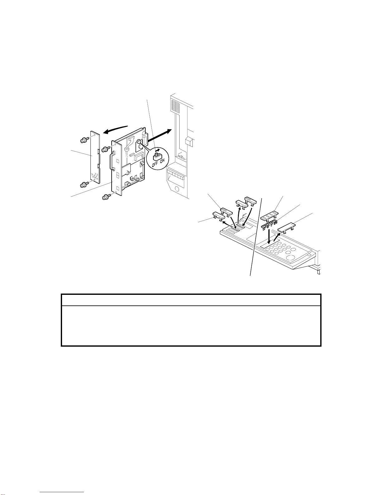
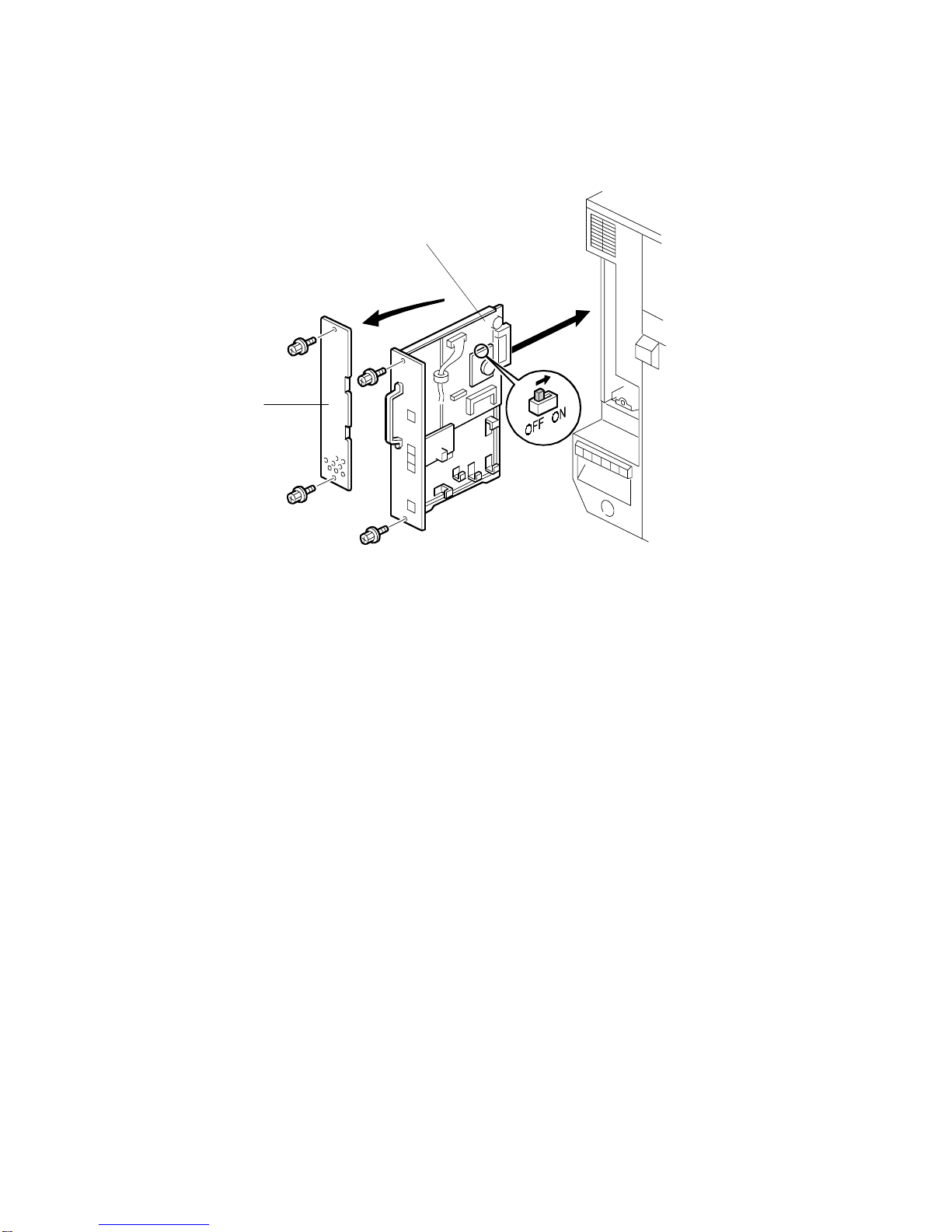
1.1.2 FAX OPTION INSTALLATION .........................................................1-2
1.1.3 INSTALLING THE HANDSET ..........................................................1-4
1.2 FAX UNIT OPTIONS.................................................................................1-5
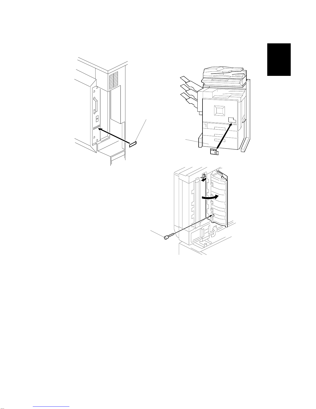
1.2.1 G3 INTERFACE UNIT INSTALLATION............................................1-5
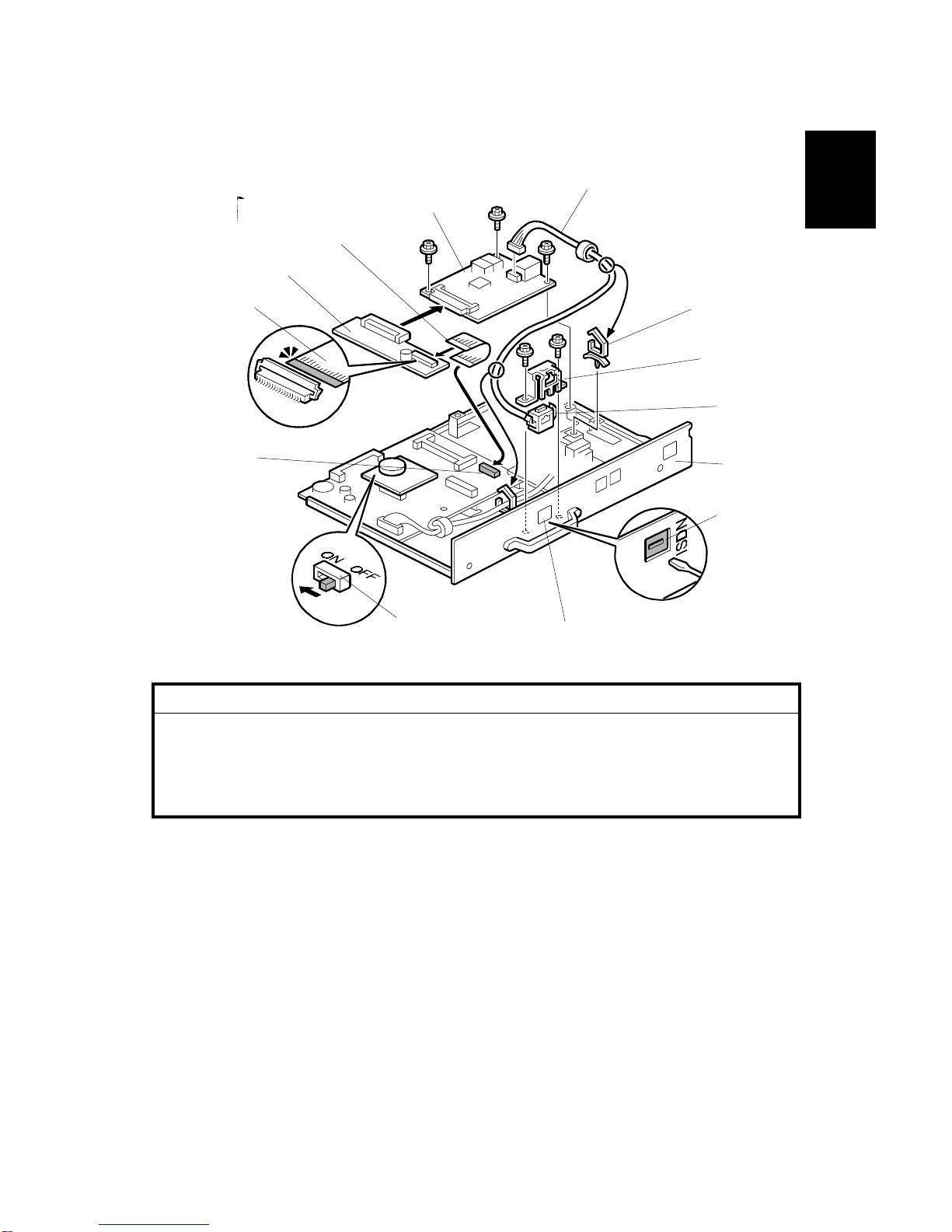
1.2.2 ISDN OPTION INSTALLATION........................................................1-7
1.2.3 FAX FUNCTION UPGRADE UNIT INSTALLATION.........................1-9
1.2.4 EXPANSION MEMORY INSTALLATION.......................................1-10
2. TROUBLESHOOTING ................................................................ 2-1
2.1 ERROR CODES........................................................................................2-1
2.2 ERROR CODES FOR THE ISDN OPTION...............................................2-9
2.2.1 D-CHANNEL LAYER MANAGEMENT ...........................................2-10
2.2.2 D-CHANNEL, LAYER 1..................................................................2-10
2.2.3 D-CHANNEL LINK LAYER.............................................................2-10
2.2.4 D-CHANNEL NETWORK LAYER...................................................2-11
2.2.5 B-CHANNEL LINK LAYER.............................................................2-11
2.2.6 B-CHANNEL NETWORK LAYER...................................................2-12
2.2.7 TRANSPORT LAYER.....................................................................2-12
2.2.8 SESSION LAYER...........................................................................2-13
2.2.9 DOCUMENT LAYER......................................................................2-14
2.2.10 PRESENTATION LAYER.............................................................2-14
2.3 FAX SC CODES......................................................................................2-15
2.3.1 OVERVIEW ....................................................................................2-15
2.3.2 SC1201...........................................................................................2-15
2.3.3 SC1207...........................................................................................2-15
2.3.4 FAX SC CODE TABLE...................................................................2-16
2.4 ISDN TEST FUNCTION ..........................................................................2-17
2.4.1 LEDS..............................................................................................2-17
2.4.2 BACK-TO-BACK TEST...................................................................2-18
3. SERVICE TABLES...................................................................... 3-1
3.1 SERVICE PROGRAM MODE....................................................................3-1
3.1.1 SERVICE PROGRAM MODE OPERATION.....................................3-1
Entering and Exiting SP mode..............................................................3-1
SP Mode Button Summary ...................................................................3-2
Switching Between SP Mode and Copy Mode for Test Printing ...........3-3
Selecting the Program Number.............................................................3-3
3.1.2 SERVICE PROGRAM MODE TABLES............................................3-4
3.2 BIT SWITCHES.........................................................................................3-9
3.2.1 SYSTEM SWITCHES.......................................................................3-9
3.2.2 SCANNER SWITCHES..................................................................3-22
3.2.3 PRINTER SWITCHES....................................................................3-26

ii
3.2.4 COMMUNICATION SWITCHES.....................................................3-31
3.2.5 G3 SWITCHES...............................................................................3-40
3.2.6 G3-2 SWITCHES............................................................................3-47
3.2.7 G4 INTERNAL SWITCHES............................................................3-53
3.2.8 G4 PARAMETER SWITCHES........................................................3-60
3.3 NCU PARAMETERS...............................................................................3-63
3.4 DEDICATED TRANSMISSION PARAMETERS......................................3-74
3.4.1 PROGRAMMING PROCEDURE....................................................3-74
3.4.2 PARAMETERS...............................................................................3-75
3.5 SERVICE RAM ADDRESSES.................................................................3-79
4. DETAILED SECTION DESCRIPTIONS ...................................... 4-1
4.1 OVERVIEW...............................................................................................4-1
4.2 BOARDS...................................................................................................4-2
4.2.1 FCU..................................................................................................4-2
4.2.2 MBU..................................................................................................4-3
4.2.3 NCU (US) .........................................................................................4-4
4.2.4 NCU (EUROPE/ASIA)......................................................................4-5
4.2.5 SG3 BOARD.....................................................................................4-6
4.2.6 SIG4 BOARD....................................................................................4-7
4.3 VIDEO DATA PATH..................................................................................4-8
4.3.1 TRANSMISSION ..............................................................................4-8
Memory Transmission and Parallel Memory Transmission...................4-9
Immediate Transmission.......................................................................4-9
JBIG Transmission ...............................................................................4-9
I-G3 (ISDN G3) Transmission...............................................................4-9
Adjustments..........................................................................................4-9
4.3.2 RECEPTION...................................................................................4-10
4.4 FAX COMMUNICATION FEATURES .....................................................4-12
4.4.1 PERSONAL/INFORMATION/TRANSFER BOXES.........................4-12
Personal Box (Confidential Box).........................................................4-12
Transfer Box.......................................................................................4-13
Information Box (Polling Tx)................................................................4-14
4.4.2 MULTI-PORT COMMUNICATION..................................................4-15
4.4.3 DOCUMENT SERVER...................................................................4-16
4.4.4 LAN FAX DRIVER..........................................................................4-17
Regular transmission..........................................................................4-18
Print and transmission ........................................................................4-18
Using Document Server......................................................................4-18
SPECIFICATIONS.....................................................................SPEC-1
1. GENERAL SPECIFICATIONS.............................................................SPEC-1
2. CAPABILITIES OF PROGRAMMABLE ITEMS...................................SPEC-3
3. MACHINE CONFIGURATION.............................................................SPEC-4

21 December, 2001 FAX UNIT
1-1
Installation
1. INSTALLATION
1.1 FAX UNIT
1.1.1 CAUTIONS
NOTE: 1) Never install telephone wiring during a lightning storm.
2) Never install telephone jacks in wet locations unless the jack is
specifically designed for wet locations.
3) Never touch uninsulated telephone wires or terminals unless the
telephone line has been disconnected at the network interface.
4) Use caution when installing or modifying telephone lines.
5) Avoid using a telephone (other than a cordless type) during an electrical
storm. There may be a remote risk of electric shock from lightning.
6) If there is a gas leak, do not use the telephone in the vicinity of the leak
to report it.
!CAUTION
1. Before installing the fax unit, switch off the main power and operation
switches, and disconnect the power cord.
2. The fax unit contains a lithium battery. The danger of explosion exists if
a battery of this type is incorrectly replaced. Replace only with the same
or an equivalent type recommended by the manufacturer. Discard used
batteries in accordance with the manufacturer’s instructions.
Note for Australia:
Unit shall be connected to Telecommunication Network through a line cord which
meets the requirements of ACA Technical Standard TS008.

FAX UNIT 21 December, 2001
1-2
1.1.2 FAX OPTION INSTALLATION
!CAUTION
Before installing this option, do the following:
1. Print out all data in the printer buffer.
2. Turn off the main switch and disconnect the power cord and the
network cable.
1. Remove the rear left cover plate [A] (!x 2).
2. Turn on the DIP switch [B] on the MBU board, then install the fax unit [C]
(!x 2).
NOTE: Make sure that the controller unit is installed when inserting the fax
unit. If the controller unit is installed after the fax unit has been
installed, this may cause poor connection between the fax unit and
controller unit.
3. Remove the cover key tops [D] and install key tops [E]/[F] and cover [G].
4. Attach the FCC decal (only for US/Canada) to the rear cover.
G307I501.WMF
G307I104.WMF
[A]
[C]
[B]
[D]
[F]
[G]
[E]
[D]

21 December, 2001 FAX UNIT
1-3
Installation
5. Attach the serial number decal [A] to the rear cover.
6. Attach the super G3 decal [B] as shown
7. If the ADF has been installed, insert the stamp cartridge [C] into the ADF as
shown.
8. Connect the telephone line to the “LINE” jack at the rear of the machine.
9. Plug in the machine and turn on the main power switch.
NOTE: The machine must be connected to a properly-grounded socket outlet.
10. Be sure to set the clock. (Date and time)
11. Enter service mode and program the serial number into the fax unit (SP3-102-
000). The serial number can be found on the serial number label (attached to
the machine in step 5).
G307I507.WMF
G307I105.WMF
G307I106.WMFWMF
[B]
[A]
[C]

FAX UNIT 21 December, 2001
1-4
1.1.3 INSTALLING THE HANDSET
NOTE: The optional handset is for the U.S. model only.
1. Remove the thumb screw [A] on the left spacer.
2. Install the handset bracket [B] on the left arm (2 screws, 1 thumb screw).
3. Install the handset holder [C] on the bracket (2 screws).
4. Place the handset [D] with the handset cord resting on the cord holder [E] of
the bracket.
5. Connect the handset cord to the jack.
G307I114.WMF
[A]
[B]
[C]
[D]
[E]

21 December, 2001 FAX UNIT OPTIONS
1-5
Installation
1.2 FAX UNIT OPTIONS
1.2.1 G3 INTERFACE UNIT INSTALLATION
!CAUTION
Before installing this option, do the following:
1. Print out all data in the printer buffer.
2. Turn off the main switch and disconnect the power cord and the
network.
1. Remove the jack window (LINE2) [A] from the panel plate [B].
2. Install the G3 board [C] and NCU board [D] (3 screws each).
3. Attach the harness clamp [E].
4. Connect the harness [F] to the connectors on G3 and NCU boards (harness
clamp [E]).
5. Connect the flat cable [G] to the connector [H] on the FCU board.
6. Connect the I/F board [I] to the G3 board and connect the flat cable [G] to the
I/F board.
NOTE: When installing the fax unit and G3 unit simultaneously, turn on the DIP
switch [J] on the MBU board.
G307I511.WMF
[B]
[A]
[G]
[D]
[E]
[F]
[C]
[I]
[G]
[J]
[H]

FAX UNIT OPTIONS 21 December, 2001
1-6
7. Remove the rear left cover plate [A] and install the fax unit [B] (2 screws each).
NOTE: Make sure that the controller unit is installed when inserting the fax
unit. If the controller unit is installed after the fax unit has been
installed, this may cause poor connection between the fax unit and
controller unit.
8. Connect the cable to the LINE2 jack, then plug in the machine and turn the
main switch on.
9. Attach the FCC/IC approval label to the machine near the ISDN jack (this step
is only for US/Canada).
10. Enter the service mode and set bit 1 of communication switch 16 to “1”, then
turn the main switch off and on.
11. Print the system parameter list and ensure that “SG3-V34” is listed as an
option.
12. Set up and program the items required for PSTN-2 communications.
G307I101.WMF
[A]
[B]

21 December, 2001 FAX UNIT OPTIONS
1-7
Installation
1.2.2 ISDN OPTION INSTALLATION
!CAUTION
Before installing this option, do the following:
1. Print out all data in the printer buffer.
2. Turn off the main switch and disconnect the power cord and the
network cable.
1. Remove the jack window (ISDN) [A] from the panel [B].
2. Install the G4 unit [C] (3 screws) and harness clamp.
3. Connect the flat cable [D] to the connector [E] on the FCU board.
4. Connect the I/F board [F] to the G4 unit and connect the flat cable [D] to the I/F
board.
5. Attach the modular socket [G] to the bracket [H] and install the bracket (2
screws).
6. Connect the cable [I] to the G4 unit and route the cable (2 clamps [J]).
NOTE: When installing the fax unit and G4 unit simultaneously, turn on the DIP
switch [K] on the MBU board.
G307I521.WMF
[K]
[C]
[D]
[F]
[A]
[B]
[J]
[J]
[I]
[H]
[D]
[E]
[G]

FAX UNIT OPTIONS 21 December, 2001
1-8
7. Remove the rear left cover [A] and install the fax unit [B] (!x 2 each).
NOTE: Make sure that the controller unit is installed when inserting the fax
unit.
If the controller unit is installed after the fax unit has been installed, this
may cause poor connection between the fax unit and controller unit.
8. Connect the cable to the ISDN jack, then plug in the machine and turn the main
switch on.
9. Attach the FCC/IC approval label to the machine near the ISDN jack (this step
is only for US/Canada).
10. Enter service mode and set bit 2 of communication switch 16 to "1". After that,
turn the main switch off and on.
11. Print the system parameter list and ensure that "G4" is listed as an option.
12. Set up and program the items required for ISDN communications. After setting
up the ISDN parameters, be sure to turn the main switch off and on.
G307I101.WMF
[A]
[B]

21 December, 2001 FAX UNIT OPTIONS
1-9
Installation
1.2.3 FAX FUNCTION UPGRADE UNIT INSTALLATION
!CAUTION
Before installing this option, do the following:
1. Print out all data in the printer buffer.
2. Turn off the main switch and disconnect the power cord and the
network cable.
1. Turn on the DIP switch [A] on the fax function upgrade unit [B].
2. Attach the stand [C] to this unit.
3. Connect the fax function upgrade unit to CN621 and attach the stand to the
board.
4. Turn the main switch off and on.
5. Enter service mode and set bit 7 of system switch 1E to “1”
NOTE: When installing the fax unit and fax function upgrade unit at the same time,
turn on the DIP switch [D] on the MBU board.
G307I103.WMF
[A]
[B]
[C]
[D]

FAX UNIT OPTIONS 21 December, 2001
1-10
1.2.4 EXPANSION MEMORY INSTALLATION
!CAUTION
Before installing this option, do the following:
1. Print out all data in the printer buffer.
2. Turn off the main switch and disconnect the power cord and the
network cable.
1. Slide the expansion memory [A] into the CN602 slot and tilt it down until it is
locked by the pin [B].
NOTE: When installing the fax unit and expansion memory at the same time, turn
on the DIP switch [C] on the MBU board.
G307I102.WMF
[A]
[C]
[B]

21 December, 2001 ERROR CODES
2-1
Trouble-
shooting
2. TROUBLESHOOTING
2.1 ERROR CODES
If an error code occurs, retry the communication. If the same problem occurs, try to
fix the problem as suggested below. Note that some error codes appear only in the
error code display and on the service report.
Code Meaning Suggested Cause/Action
0-00 DIS/NSF not detected within
40 s of Start being pressed •Check the line connection.
•Check the NCU - FCU connectors.
•The machine at the other end may be
incompatible.
•Replace the NCU or FCU.
•Check for DIS/NSF with an oscilloscope.
•If the rx signal is weak, there may be a bad line.
0-01 DCN received unexpectedly •The other party is out of paper or has a jammed
printer.
•The other party pressed Stop during
communication.
0-03 Incompatible modem at the
other end •The other terminal is incompatible.
0-04 CFR or FTT not received
after modem training •Check the line connection.
•Check the NCU - FCU connectors.
•Try changing the tx level and/or cable equalizer
settings.
•Replace the FCU or NCU.
•The other terminal may be faulty; try sending to
another machine.
•If the rx signal is weak or defective, there may be
a bad line.
Cross reference
•Tx level - NCU Parameter 01 (PSTN)
•Cable equalizer - G3 Switch 07 (PSTN)
•Dedicated Tx parameters - Section 4
0-05 Unsuccessful after modem
training at 2400 bps •Check the line connection.
•Check the NCU - FCU connectors.
•Try adjusting the tx level and/or cable equalizer.
•Replace the FCU or NCU.
•Check for line problems.
Cross reference
•See error code 0-04.

ERROR CODES 21 December, 2001
2-2
Code Meaning Suggested Cause/Action
0-06 The other terminal did not
reply to DCS •Check the line connection.
•Check the FCU - NCU connectors.
•Try adjusting the tx level and/or cable equalizer
settings.
•Replace the NCU or FCU.
•The other end may be defective or incompatible;
try sending to another machine.
•Check for line problems.
Cross reference
•See error code 0-04.
0-07 No post-message response
from the other end after a
page was sent
•Check the line connection.
•Check the FCU - NCU connectors.
•Replace the NCU or FCU.
•The other end may have jammed or run out of
paper.
•The other end user may have disconnected the
call.
•Check for a bad line.
•The other end may be defective; try sending to
another machine.
0-08 The other end sent RTN or
PIN after receiving a page,
because there were too
many errors
•Check the line connection.
•Check the FCU - NCU connectors.
•Replace the NCU or FCU.
•The other end may have jammed, or run out of
paper or memory space.
•Try adjusting the tx level and/or cable equalizer
settings.
•The other end may have a defective
modem/NCU/FCU; try sending to another
machine.
•Check for line problems and noise.
Cross reference
•Tx level - NCU Parameter 01 (PSTN)
•Cable equalizer - G3 Switch 07 (PSTN)
•Dedicated Tx parameters - Section 4
0-14 Non-standard post message
response code received •Check the FCU - NCU connectors.
•Incompatible or defective remote terminal; try
sending to another machine.
•Noisy line: resend.
•Try adjusting the tx level and/or cable equalizer
settings.
•Replace the NCU or FCU.
Cross reference
•See error code 0-08.

21 December, 2001 ERROR CODES
2-3
Trouble-
shooting
Code Meaning Suggested Cause/Action
0-15 The other terminal is not
capable of specific
functions.
The other terminal is not capable of accepting the
following functions, or the other terminal’s memory
is full.
•Confidential rx
•Transfer function
•SEP/SUB/PWD/SID
0-16 CFR or FTT not detected
after modem training in
confidential or transfer mode
•Check the line connection.
•Check the FCU - NCU connectors.
•Replace the NCU or FCU.
•Try adjusting the tx level and/or cable equalizer
settings.
•The other end may have disconnected, or it may
be defective; try calling another machine.
•If the rx signal level is too low, there may be a
line problem.
Cross reference
•See error code 0-08.
0-17 Communication was
interrupted by pressing the
Stop key.
If the Stop key was not pressed and this error keeps
occurring, replace the operation panel.
0-20 Facsimile data not received
within 6 s of retraining •Check the line connection.
•Check the FCU - NCU connectors.
•Replace the NCU or FCU.
•Check for line problems.
•Try calling another fax machine.
•Try adjusting the reconstruction time for the first
line and/or rx cable equalizer setting.
Cross reference
•Reconstruction time - G3 Switch 0A, bit 6
•Rx cable equalizer - G3 Switch 07 (PSTN)
0-21 EOL signal (end-of-line)
from the other end not
received within 5 s of the
previous EOL signal
•Check the connections between the FCU, NCU,
& line.
•Check for line noise or other line problems.
•Replace the NCU or FCU.
•The remote machine may be defective or may
have disconnected.
Cross reference
•Maximum interval between EOLs and between
ECM frames - G3 Bit Switch 0A, bit 4
0-22 The signal from the other
end was interrupted for
more than the acceptable
modem carrier drop time
(default: 200 ms)
•Check the line connection.
•Check the FCU - NCU connectors.
•Replace the NCU or FCU.
•Defective remote terminal.
•Check for line noise or other line problems.
•Try adjusting the acceptable modem carrier drop
time.
Cross reference
•Acceptable modem carrier drop time - G3 Switch
0A, bits 0 and 1

ERROR CODES 21 December, 2001
2-4
Code Meaning Suggested Cause/Action
0-23 Too many errors during
reception •Check the line connection.
•Check the FCU - NCU connectors.
•Replace the NCU or FCU.
•Defective remote terminal.
•Check for line noise or other line problems.
•Try asking the other end to adjust their tx level.
•Try adjusting the rx cable equalizer setting and/or
rx error criteria.
Cross reference
•Rx cable equalizer - G3 Switch 07 (PSTN)
•Rx error criteria - Communication Switch 02, bits
0 and 1
0-30 The other terminal did not
reply to NSS(A) in AI short
protocol mode
•Check the line connection.
•Check the FCU - NCU connectors.
•Try adjusting the tx level and/or cable equalizer
settings.
•The other terminal may not be compatible.
Cross reference
•Dedicated tx parameters - Section 4
0-32 The other terminal sent a
DCS, which contained
functions that the receiving
machine cannot handle.
•Check the protocol dump list.
•Ask the other party to contact the manufacturer.
0-52 Polarity changed during
communication •Check the line connection.
Retry communication.
0-70 The communication mode
specified in CM/JM was not
available
(V.8 calling and called
terminal)
•The other terminal did not have a compatible
communication mode (e.g., the other terminal
was a V.34 data modem and not a fax modem.)
•A polling tx file was not ready at the other
terminal when polling rx was initiated from the
calling terminal.
0-74 The calling terminal fell back
to T.30 mode, because it
could not detect ANSam
after sending CI.
•The calling terminal could not detect ANSam due
to noise, etc.
•ANSam was too short to detect.
•Check the line connection and condition.
•Try making a call to another V.8/V.34 fax.
0-75 The called terminal fell back
to T.30 mode, because it
could not detect a CM in
response to ANSam
(ANSam timeout).
•The terminal could not detect ANSam.
•Check the line connection and condition.
•Try receiving a call from another V.8/V.34 fax.
0-76 The calling terminal fell back
to T.30 mode, because it
could not detect a JM in
response to a CM
(CM timeout).
•The called terminal could not detect a CM due to
noise, etc.
•Check the line connection and condition.
•Try making a call to another V.8/V.34 fax.

21 December, 2001 ERROR CODES
2-5
Trouble-
shooting
Code Meaning Suggested Cause/Action
0-77 The called terminal fell back
to T.30 mode, because it
could not detect a CJ in
response to JM
(JM timeout).
•The calling terminal could not detect a JM due to
noise, etc.
•A network that has narrow bandwidth cannot
pass JM to the other end.
•Check the line connection and condition.
•Try receiving a call from another V.8/V.34 fax.
0-79 The called terminal detected
CI while waiting for a V.21
signal.
Check for line noise or other line problems.
If this error occurs, the called terminal falls back to
T.30 mode.
0-80 The line was disconnected
due to a timeout in V.34
phase 2 – line probing.
0-81 The line was disconnected
due to a timeout in V.34
phase 3 – equalizer training.
0-82 The line was disconnected
due to a timeout in the V.34
phase 4 – control channel
start-up.
0-83 The line was disconnected
due to a timeout in the V.34
control channel restart
sequence.
•The guard timer expired while starting these
phases. Serious noise, narrow bandwidth, or low
signal level can cause these errors.
If these errors happen at the transmitting terminal:
•Try making a call at a later time.
•Try using V.17 or a slower modem using
dedicated tx parameters.
•Try increasing the tx level.
•Try adjusting the tx cable equalizer setting.
If these errors happen at the receiving terminal:
•Try adjusting the rx cable equalizer setting.
•Try increasing the tx level.
•Try using V.17 or a slower modem if the same
error is frequent when receiving from multiple
senders.
0-84 The line was disconnected
due to abnormal signaling in
V.34 phase 4 – control
channel start-up.
•The signal did not stop within 10 s.
•Turn off the machine, then turn it back on.
•If the same error is frequent, replace the FCU.
0-85 The line was disconnected
due to abnormal signaling in
V.34 control channel restart.
•The signal did not stop within 10 s.
•Turn off the machine, then turn it back on.
•If the same error is frequent, replace the FCU.
0-86 The line was disconnected
because the other terminal
requested a data rate using
MPh that was not available
in the currently selected
symbol rate.
•The other terminal was incompatible.
•Ask the other party to contact the manufacturer.
0-87 The control channel started
after an unsuccessful
primary channel.
•The receiving terminal restarted the control
channel because data reception in the primary
channel was not successful.
•This does not result in an error communication.
0-88 The line was disconnected
because PPR was
transmitted/received 9
(default) times within the
same ECM frame.
•Try using a lower data rate at the start.
•Try adjusting the cable equalizer setting.
2-10 The modem cannot enter tx
mode •Replace the FCU.
2-11 Only one V.21 connection
flag was received •Replace the FCU.

ERROR CODES 21 December, 2001
2-6
Code Meaning Suggested Cause/Action
2-12 Modem clock irregularity •Replace the FCU.
2-13 Modem initialization error •Turn off the machine, then turn it back on.
•Update the modem ROM.
•Replace the FCU.
2-20 Abnormal coding/decoding
(cpu not ready) •Replace the FCU.
2-23 JBIG compression or
reconstruction error •Turn off the machine, then turn it back on.
•Replace the EXFUNC board if the error is
frequent.
2-24 JBIG ASIC error •Turn off the machine, then turn it back on.
•Replace the EXFUNC board if the error is
frequent.
2-25 JBIG data reconstruction
error (BIH error)
2-26 JBIG data reconstruction
error (Float marker error)
2-27 JBIG data reconstruction
error (End marker error)
2-28 JBIG data reconstruction
error (Timeout)
•JBIG data error
•Check the sender’s JBIG function.
•Update the MBU ROM.
2-50 The machine resets itself for
a fatal FCU system error •If this is frequent, update the ROM, or replace the
FCU.
2-51 The machine resets itself
because of a fatal
communication error
•If this is frequent, update the ROM, or replace the
FCU.
3-00 G4 interface board reset •Replace the G4 interface board or FCU.
3-10 Disconnection during ISDN
G3 communication •Check the other terminal and the ISDN line.
•The other terminal may have dialed a wrong
number.
3-11 Disconnection during ISDN
G4 communication •Check the other terminal and the ISDN line.
3-20 A CSA signal was received
during ISDN G4
communication
•The operator at the other terminal may have
interrupted the communication.
3-21 A CSA signal was sent
during ISDN G4
communication, because the
Stop key was pressed
•The local operator has interrupted the
communication.
3-30 Mismatched specifications
(rx capability) •Check the receive capabilities requested from the
other terminal.
4-01 Line current was cut •Check the line connector.
•Check the connection between FCU and NCU.
•Check for line problems.
•Replace the FCU or the NCU.
4-10 Communication failed
because of an ID Code
mismatch (Closed Network)
or Tel. No./CSI mismatch
(Protection against Wrong
Connections)
•Get the ID Codes the same and/or the CSIs
programmed correctly, then resend.
•The machine at the other end may be defective.

21 December, 2001 ERROR CODES
2-7
Trouble-
shooting
Code Meaning Suggested Cause/Action
5-00 Data construction not
possible
5-01 Data reconstruction not
possible
5-10 DCR timer expired
•Replace the FCU.
5-20 Storage impossible because
of a lack of memory •Temporary memory shortage.
•Test the SAF memory.
•Replace the FCU or optional EXMEM board
5-21 Memory overflow
5-22 Mode table overflow after
the second page of a
scanned document
•Wait for the messages which are currently in the
memory to be sent or delete some files from
memory.
5-23 Print data error when
printing a substitute rx or
confidential rx message
•Test the SAF memory.
•Ask the other end to resend the message.
•Replace the FCU or optional EXMEM board.
5-24 Memory overflow after the
second page of a scanned
document
•Try using a lower resolution setting.
•Wait for the messages which are currently in the
memory to be sent or delete some files from
memory.
5-25 SAF file access error •Replace the FCU or EXMEM board.
6-00 G3 ECM - T1 time out
during reception of facsimile
data
6-01 G3 ECM - no V.21 signal
was received
6-02 G3 ECM - EOR was
received
•Try adjusting the rx cable equalizer.
•Replace the FCU or NCU.
6-04 G3 ECM - RTC not detected •Check the line connection.
•Check connections from the NCU to the FCU.
•Check for a bad line or defective remote terminal.
•Replace the FCU or NCU.
6-05 G3 ECM - facsimile data
frame not received within 18
s of CFR, but there was no
line fail
•Check the line connection.
•Check connections from the NCU to the FCU.
•Check for a bad line or defective remote terminal.
•Replace the FCU or NCU.
•Try adjusting the rx cable equalizer
Cross reference
•Rx cable equalizer - G3 Switch 07 (PSTN)
6-06 G3 ECM - coding/decoding
error •Defective FCU.
•The other terminal may be defective.
6-08 G3 ECM - PIP/PIN received
in reply to PPS.NULL •The other end pressed Stop during
communication.
•The other terminal may be defective.
6-09 G3 ECM - ERR received •Check for a noisy line.
•Adjust the tx levels of the communicating
machines.
•See code 6-05.
This manual suits for next models
1
Table of contents
Other Ricoh Fax Machine manuals

Ricoh
Ricoh fax2000l User manual

Ricoh
Ricoh 4420NF User manual

Ricoh
Ricoh FAX3800L User manual

Ricoh
Ricoh Aficio FAX5000L User manual

Ricoh
Ricoh infotec 3671F User manual

Ricoh
Ricoh Stella-C1 Service manual

Ricoh
Ricoh HL-F1 Quick start guide

Ricoh
Ricoh 1195L User manual

Ricoh
Ricoh F102 User manual

Ricoh
Ricoh MV310E User manual

Ricoh
Ricoh Fax 2210L User manual

Ricoh
Ricoh Fax 2210L User manual

Ricoh
Ricoh Fax 2100L User manual

Ricoh
Ricoh 1195L User manual

Ricoh
Ricoh FT5233 User manual

Ricoh
Ricoh B383 User manual

Ricoh
Ricoh FAX220 User manual

Ricoh
Ricoh 4410L User manual

Ricoh
Ricoh FAX 1190L User manual

Ricoh
Ricoh fax1900L User manual