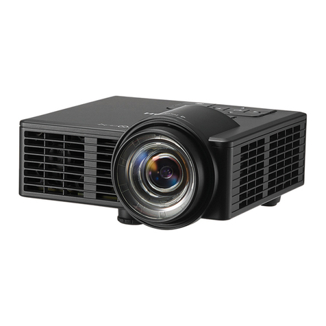
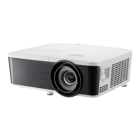
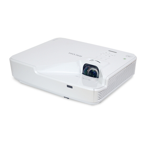
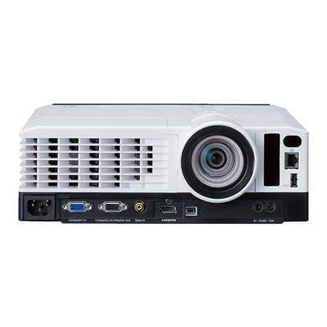
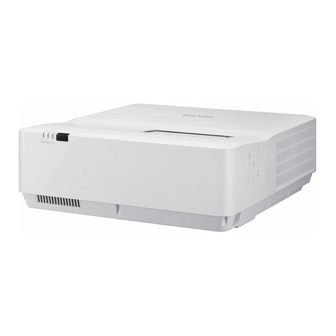
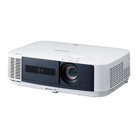
Ricoh PJK7000 Quick start guide

Deneb-PJ1
Machine Codes: Y041
Field Service Manual
26 December, 2013

Important Safety Notices
Prevention of physical injury
1. Before disassembling or assembling parts of the main machine and peripherals, make sure that the
power cord of the main machine is unplugged.
2. The wall outlet should be near the machine and easily accessible.
3. If any adjustment or operation check has to be made with exterior covers off or open while the
main switch is turned on, keep hands away from electrified or mechanically driven components.
• To prevent a fire or explosion, keep the machine away from flammable liquids, gases, and
aerosols.
Health safety conditions
• This machine, which uses a high voltage power source, can generate ozone gas. High ozone
density is harmful to human health. Therefore, the machine must be installed in a well-ventilated
room.
Observance of electrical safety standards
• This machine and its peripherals must be serviced by a customer service representative who has
completed the training course on those models.
Safety and Ecological Notes for Disposal
• Dispose of replaced parts in accordance with local regulations.
1

TABLE OF CONTENTS
Important Safety Notices...................................................................................................................................1
Important Safety Notices...............................................................................................................................1
Prevention of physical injury.................................................................................................................1
Health safety conditions........................................................................................................................1
Observance of electrical safety standards..........................................................................................1
Safety and Ecological Notes for Disposal...................................................................................................1
1. Product Information
Overview.............................................................................................................................................................7
Main Unit........................................................................................................................................................7
Control Panel..................................................................................................................................................8
Connection Ports.............................................................................................................................................9
Specifications....................................................................................................................................................10
General Specifications................................................................................................................................10
Compatible Mode.......................................................................................................................................11
Computer compatibility for PC...........................................................................................................11
Computer compatibility for MAC......................................................................................................14
GEO Board Limitation.................................................................................................................................16
Lamp Information.........................................................................................................................................16
Lens...............................................................................................................................................................17
2. Installation
Installation Requirements.................................................................................................................................21
Environment/Power Requirements.............................................................................................................21
Machine Space Requirements....................................................................................................................21
Machine Dimensions...................................................................................................................................21
Main Machine Installation...............................................................................................................................22
Accessory Check..........................................................................................................................................22
Precautions...................................................................................................................................................23
Do..................................................................................................................................................................23
Do not...........................................................................................................................................................23
GEO Board Installation...................................................................................................................................24
Installation Procedure..................................................................................................................................24
3. Replacement and Adjustment
Special Tools....................................................................................................................................................27
2

Equipment Needed..........................................................................................................................................28
Parts List.............................................................................................................................................................29
Service Parts List...........................................................................................................................................29
Part Replacement..............................................................................................................................................31
Lens Ring Cover, Projector Lens..................................................................................................................31
Lamp Cover, Lamp Unit...............................................................................................................................33
Top Cover, IR-T Sensor................................................................................................................................34
Rear Cover...................................................................................................................................................35
Main Board, GEO Dummy Board, I/O Board, LAN Board...................................................................37
Connector list.......................................................................................................................................40
Blower Module............................................................................................................................................42
Top blower and duct...........................................................................................................................42
TC blower............................................................................................................................................43
Bottom blower and duct.....................................................................................................................44
System Fan....................................................................................................................................................45
Main Board Shielding and Front Shielding...............................................................................................47
Front Cover, LED Board, LED Cover, Thermal Board, IR Cover..............................................................49
Right Cover, Lamp Cover............................................................................................................................50
Left Cover, Keypad Rubber, Keypad Board, Speaker, Interrupt switch.................................................51
Optical Engine.............................................................................................................................................54
Color Wheel, Photo Sensor Board.............................................................................................................56
DA module, DA Sensor Board....................................................................................................................57
Thermal Switch.............................................................................................................................................57
Lamp Driver..................................................................................................................................................58
LVPS..............................................................................................................................................................59
DMD Fan......................................................................................................................................................60
Bottom Cover, Bottom Shielding, AC inlet.................................................................................................60
Required Action After Replacing Parts ...........................................................................................................62
4. Troubleshooting
Front Panel LEDs...............................................................................................................................................65
Main Procedures..............................................................................................................................................67
A. No Power Troubleshooting....................................................................................................................68
B. Power Troubleshooting...........................................................................................................................68
3
C. Image Performance Troubleshooting....................................................................................................73
D. Remote Control Troubleshooting...........................................................................................................81
E. Network Troubleshooting.......................................................................................................................83
Rod Adjustment.................................................................................................................................................85
5. Test & Inspection
Service Mode...................................................................................................................................................87
How to Enter the Service Mode..................................................................................................................87
Service Mode Settings.................................................................................................................................87
Test Equipment and Conditions.......................................................................................................................90
Test Equipment Needed..............................................................................................................................90
Recommended Test Condition....................................................................................................................90
Calibration........................................................................................................................................................91
Lens Calibration...........................................................................................................................................91
DA Calibration.............................................................................................................................................91
Fan Calibration............................................................................................................................................92
Re-write Lamp Hours........................................................................................................................................94
Color Wheel Index..........................................................................................................................................95
Focus Adjustment..............................................................................................................................................96
Test Inspection Procedure................................................................................................................................97
Check points.................................................................................................................................................97
OSD Reset....................................................................................................................................................97
Network Test.....................................................................................................................................................98
6. Firmware Update
PIC/PW392/DDP2431 FW Update............................................................................................................99
Equipment Needed......................................................................................................................................99
Firmware Update Procedure.......................................................................................................................99
Connection...........................................................................................................................................99
Download software and update.....................................................................................................100
Check the PW392/PIC/DDP2431 FW version ..........................................................................103
LAN Firmware Update Procedure................................................................................................................104
Equipment Needed...................................................................................................................................104
Connect the Projector & Check the LAN Setting.....................................................................................104
PC Network Setting...................................................................................................................................106
4

Proxy Setting..............................................................................................................................................107
LAN FW Update Procedure.....................................................................................................................108
Check LAN FW Version............................................................................................................................111
Re-write Serial Number (S/N).....................................................................................................................112
Equipment Needed...................................................................................................................................112
Re-write Serial Number (S/N).................................................................................................................112
Connection........................................................................................................................................112
Re-write serial number (S/N)..........................................................................................................113
Check Serial Number (S/N)....................................................................................................................116
5

6

1. Product Information
Overview
Main Unit
1. Lens ring
2. Zoom lens
3. IR receivers
4. LED indicators
5. Lamp door
6. Outlet vent
7

7. Kensington lock
8. Security bar
9. Power switch
10. Power connector
11. Connector panel
12. Inlet vent & filter
13. Audio vent
14. Keypad panel
Control Panel
1. / Power key
2. Menu key
3. Enter key
4. Exit key
5. Lens key
6. Auto key
7. Focus key
1. Product Information
8

8. Zoom key
9. Input key
10. Info. key
11. Four directional select keys
Connection Ports
1. Composite video input connector
2. HDMI connector
3. DVI-D connector
4. BNC connector
5. Wired remote input connector
6. 12V trigger relay connector
7. LAN connector
8. S-Video input connector
9. Computer In connector (VGA input)
10. Monitor out connector (VGA output)
11. Audio input connector
12. Audio output connector
13. RS232 connector (9-pin DIN type)
Overview
9

Specifications
General Specifications
No Item Description
1 Technology “TI” DMD 12,0.7” XGA, type A, DC3
2 Dimension (W x D x H) 453 x 390 x 212 mm (without lens, with elevators)
3 Power supply Auto-ranging: 100V ~ 240V ± 10%, 50-60Hz
4 Keystone correction • V: +/- 20 degree
• H: +/- 20 degree
5 Resolution Native resolution: 1024x 768
6 Power consumption
• Normal Brightness mode: 500W maximum
• ECO Brightness mode: 370W
• Standby mode (LAN off) < 0.5W
7 Throw ratio
• 0.99-1.26 (Replacement Lens Type 5)
• 1.26-1.58 (Standard Lens Type 2)
• 1.58-3.00 (Replacement Lens Type 6)
8 Lamp life
• 1500 hours standard @370W, 50% survival rate
(normal mode)
• 2000 hours typical @280W, 50% survival rate (ECO
mode)
9 Video compatibility
• NTSC: NTSC M 3.58MHz, 4.43MHz
• PAL: PAL B/D/G/H/I/M/N, 4.43MHz
• SECAM: SECAM B/D/G/K/K1/L, 4.25/4.4 MHz
• SDTV: 480i/p, 576i/p
• HDTV: 720p(50/60Hz), 1080i/p(50/60Hz), 1080p
24\25\30\50\60 Hz
10 Brightness • Marketing: 6,000
11 Contrast ratio • Marketing: 4,400:1 Maximum (Dynamic ON)
1. Product Information
10

No Item Description
12 Uniformity • Typical: 90%, Minimum: 80%(BMA standard)
• Typical: +/-20%, Minimum: +/-35%(ANSI standard)
13 Color wheel • 6 Segment—RGBCYW, 56mm
• 2X, 7200RPM (120Hz) & 3X, 10800RPM (180Hz)
14 Lamp 370W
15 Projection lens
• Zoom range (ratio): LEN-008: 1.28X; LEN-009: 1.25X;
LEN-010: 1.9X
• Throw ratio: LEN-008: 0.99-1.26; LEN-009:
1.26-1.58; LEN-010: 1.58-3.00
• Throw distance: LEN-008:1.01~7.68m; LEN-009:
1.28~9.63m; LEN-010: 1.61~18.29m
• Motorized lens shift: Horizontal: +/-15% (tolerance
+/-4%) Vertical: +/-50% (tolerance +/-4%) (Dim
corner larger than 50%)
• Projection Image Size: 50~300
16 Temperature • Operating: 5°C ~ 40 °C
• Non-operation: -20°C ~ 60°C
17 Altitude
• Operating: for 0 ~ 2500 ft, 5 ~ 40°C for 2500 ~
5000 ft, 5 ~ 30°C for 5000 ~ 10000 ft, 5 ~ 25°C
• Non-operation: Sea Level to 40,000 feet
Compatible Mode
Computer compatibility for PC
Signal Resolution Frequenc
y [KHz]
Refresh
rate
[Hz]
Video Digital Analog Remark
NTSC - 15.734 60 O - -
PAL/
SECAM - 15.625 50 O - -
Specifications
11

Signal Resolution Frequenc
y [KHz]
Refresh
rate
[Hz]
Video Digital Analog Remark
640 x 350 31.5 70.1 O O 70Hz
640 x 400 37.9 85.1 O O 85Hz
720 x 400 31.5 70 O O
720 x 400 37.9 85 O O
720 x 576 50 O O
VGA 640 x 480 31.5 60 O O
VGA 640 x 480 67 O O
VGA 640 x 480 37.9 72.8 O O 72Hz
VGA 640 x 480 37.5 75 O O
VGA 640 x 480 43.3 85 O O
SVGA 800 x 600 35.2 56.3 O O 56Hz
SVGA 800 x 600 37.9 60.3 O O 60Hz
SVGA 800 x 600 46.9 75 O O
SVGA 800 x 600 48.1 72.2 O O 72Hz
SVGA 800 x 600 53.7 85.1 O O 85Hz
832 x 624 75 O O
XGA 1024 x 768 48.4 60 O O
XGA 1024 x 768 56.5 70.1 O O 70Hz
XGA 1024 x 768 60 75 O O
XGA 1024 x 768 68.7 85 O O
1152 x 864 75 O O
HD720 1280 x 720 50 O O
HD720 1280 x 720 60 O O
1. Product Information
12

Signal Resolution Frequenc
y [KHz]
Refresh
rate
[Hz]
Video Digital Analog Remark
WXGA 1280 x 768 47.4 60 O O
WXGA 1280 x 768 75 O O
WXGA 1280 x 768 85 O O
WXGA-800 1280 x 800 60 O O
SXGA 1280 x
1024 64 60 O O
SXGA 1280 x
1024 80 75 O O
SXGA 1280 x
1024 91.1 85 O O
SXGA+ 1400 x
1050 60 O -
UXGA 1600 x1200 75 60 O O
HD1080 1920 x
1080 24 O O
HD1080 1920 x
1080 50 O O
HD1080 1920 x
1080 60 O O
WUXGA 1920 x
1200 60 O O Only support
[RB] timing
HDTV 1920 x
1080 33.8 30 O - -
1920 x
1080 28.1 25 O - - 1920 x
1080
1920 x
1080i 50 - O O 1920 x
1080i
Specifications
13

Signal Resolution Frequenc
y [KHz]
Refresh
rate
[Hz]
Video Digital Analog Remark
1920 x
1080i 60 - O O 1920 x
1080i
1920 x
1080p 24 - O O 1920 x
1080p
1920 x
1080p 25 - O O 1920 x
1080p
1920 x
1080p 30 - O O 1920 x
1080p
1920 x
1080p 50 - O O 1920 x
1080p
1920 x
1080p 60 - O O 1920 x
1080p
1280 x 720 45 60 O - - 1280 x 720
1280 x
720p 50 - O O 1280 x
720p
•“O” expressed support this type of signal and “-” expressed that does not support this type of
signal.
•If the computer compatibility supportive signal is different from User’s Manual, please refer to
User’s Manual.
Computer compatibility for MAC
Resolution Hz
Mac book
compatibility
Mac book Pro
(Intel)
compatibility
Power Mac G5
compatibility
Power Mac G4
compatibility
Digital Analog Digital Analog Digital Analog Digital Analog
800x600 60 O O O O - - O -
800x600 72 O O O O - O O O
1. Product Information
14

Resolution Hz
Mac book
compatibility
Mac book Pro
(Intel)
compatibility
Power Mac G5
compatibility
Power Mac G4
compatibility
Digital Analog Digital Analog Digital Analog Digital Analog
800x600 75 O O O O - O O O
800x600 85 O O - O - O O O
1024x76
860 O O O O - O O O
1024x76
870 O O O O - O O O
1024x76
875 O O O O - O O O
1024x76
885 O O O O - O O O
1280x72
060 O O O O - O O O
1280x76
860 O O O O - - - O
1280x76
875 - O - O - O O O
1280x76
885 - O - O - - - O
1280x80
060 - O - O - O O O
1280x10
24 60 O - - O - O O O
1280x10
24 75 O - - O - O O -
1920x10
80 60 O - - O - O O O
1920x12
00(*1) 60 O - - O - O O O
Specifications
15

(*1) 1920 x 1200 @60Hz only support RB (reduced blanking)
•“O” expressed support this type of signal and “-” expressed that does not support this type of
signal.
•If the computer compatibility supportive signal is different from User’s Manual, please refer to
User’s Manual.
GEO Board Limitation
Blending Keystone 4- Corner Curve Rotation
Pin
Cushion/
Barrel
Blending X O X X X
Keystone X X X X O
4- Corner O X X X X
Curve X X X X X
Rotation X X X X O
Pin
Cushion/
Barrel
X O X X O
Lamp Information
Description
Type 370W
Lamp life
• Normal mode1500 Hours Standard @370W, 50%
survival rate
• ECO mode2000 hours typical @280W, 50% survival
rate
Above spec only claimed for table top and ceiling mount,
CW @2X
1. Product Information
16

Description
Lamp power • Normal mode: 370W+/-5%
• ECO mode: 280W
Lens
Projection lens Replacement Lens Type
5Standard Lens Type 2 Replacement Lens Type
6
Focal length (f) 14.03-17.96 18.07-22.59 18.07-22.59
F number 2.30-2.57 2.00-2.32 2.30-3.39
Focus spec (MTF) 67 lp/mm 47 lp/mm 67 lp/mm
Zoom range (ratio) 1.28X 1.25X 1.9X
Zoom & focus
adjustment Motorized
Throw ratio (XGA) 0.99-1.26 1.26-1.58 1.58-3.00
Throw distance (XGA) 1.01~7.68m 1.28~9.63m 1.61~18.29m
Projection image size 50~300”
Specifications
17

Projection lens Replacement Lens Type
5Standard Lens Type 2 Replacement Lens Type
6
Motorized lens shift
Horizontal: +/-15% (typical; tolerance +/-4%)
Vertical: +/-50% (typical; tolerance +/-4%)
(Dim corner larger than 50%)
• Panel: 0.7” XGA
• H: 15%
• V: 50%
• H1: 0%
• V1: 20%
Lens shift accuracy: 0.5 pixel per step
Keystone correction
V: +/- 20 degree
H: +/- 20 degrees (optional warping board)
OSD adjusting range will be +/-40 steps for H and V.
Leakage <=0.8 Lx @ screen size diagonal 83” outside of active area
1. Product Information
18

Projection lens Replacement Lens Type
5Standard Lens Type 2 Replacement Lens Type
6
Distortion
<+/- 1.0% @ 100” screen size
(all lens shift area, all optional lens)
Horizontal distortion = (A-C)/C (up) and (B-C)C (down)
Vertical distortion = (D + E - 2F)/2F
Flare
1 pixel (core pixel) XGA=3.2mm @ 100“ screen
2.Green flare<=2.0 pixels (Observable from 1.5m)
3.Blue/Red flare<=2.5 pixels (Observable from 1.5m)
Unbalance <50cm @100” full range for all lens.
Thermal drift of focus About 45cm @100” after 1 hr. burn-in
Specifications
19
Table of contents
Other Ricoh Projector manuals

Ricoh
Ricoh PJ X5360N User manual

Ricoh
Ricoh PJ WX4130n User manual

Ricoh
Ricoh PJ WXC1110 User manual

Ricoh
Ricoh PJ X5360N User manual

Ricoh
Ricoh PJ X6180N User manual

Ricoh
Ricoh Furud-PJ1 Installation guide

Ricoh
Ricoh PJ XL4540 Quick start guide

Ricoh
Ricoh PJ LU8000 Series User manual

Ricoh
Ricoh IPSiO PJ X3130 User manual

Ricoh
Ricoh PJ WX5140 User manual

Ricoh
Ricoh PJ WX2440 User manual

Ricoh
Ricoh PJ WX4153 Original instructions

Ricoh
Ricoh PJ X5462 User manual

Ricoh
Ricoh PJ WX6170N Operating manual

Ricoh
Ricoh Image Pointer GP01 User manual

Ricoh
Ricoh PJ KU12000 User manual

Ricoh
Ricoh PJ WX3340N User manual

Ricoh
Ricoh PJ WUL6281 User manual

Ricoh
Ricoh PJ WX3340 User manual

Ricoh
Ricoh PJ WXC4660 User manual